Tools Required

- Measure the valve stem (1) to guide (2) clearance. Excessive valve stem-to-guide clearance may cause excessive oil consumption and may also cause a valve
to break. Insufficient clearance will result in noisy and sticky functioning of the valve and will disturb the engine assembly smoothness
- Clamp a dial indicator to the cylinder head at the camshaft cover rail.
- Locate the dial indicator so the movement of the valve stem from side to side, crossways to the cylinder head, will cause a direct movement of the indicator stem. The dial indicator stem must contact the side of the valve stem just above the valve
guide.
- Drop the valve head about 0.064 mm off the valve seat.
- Use light pressure when moving the valve stem from side to side to obtain a clearance reading.
| • | If the clearance for the valve is greater than specified and a new standard diameter valve stem will not bring the clearance within specifications, the valve guide may be oversized by 0.075 mm using
J 42096
or by 0.375 mm using
EN 46120
Two sizes of oversized valve stems are available for service. |
| • | Valve guide wear at the bottom 10 mm of the valve guide is not significant enough to affect normal operation. |
| • | If over sizing the guide does not bring the clearance within specifications, replace the cylinder head. |
Inspection
- Clean the valve springs in solvent.
- Dry the valve springs with compressed air.
- Inspect the valve springs for broken coils or coil ends.
Measurement
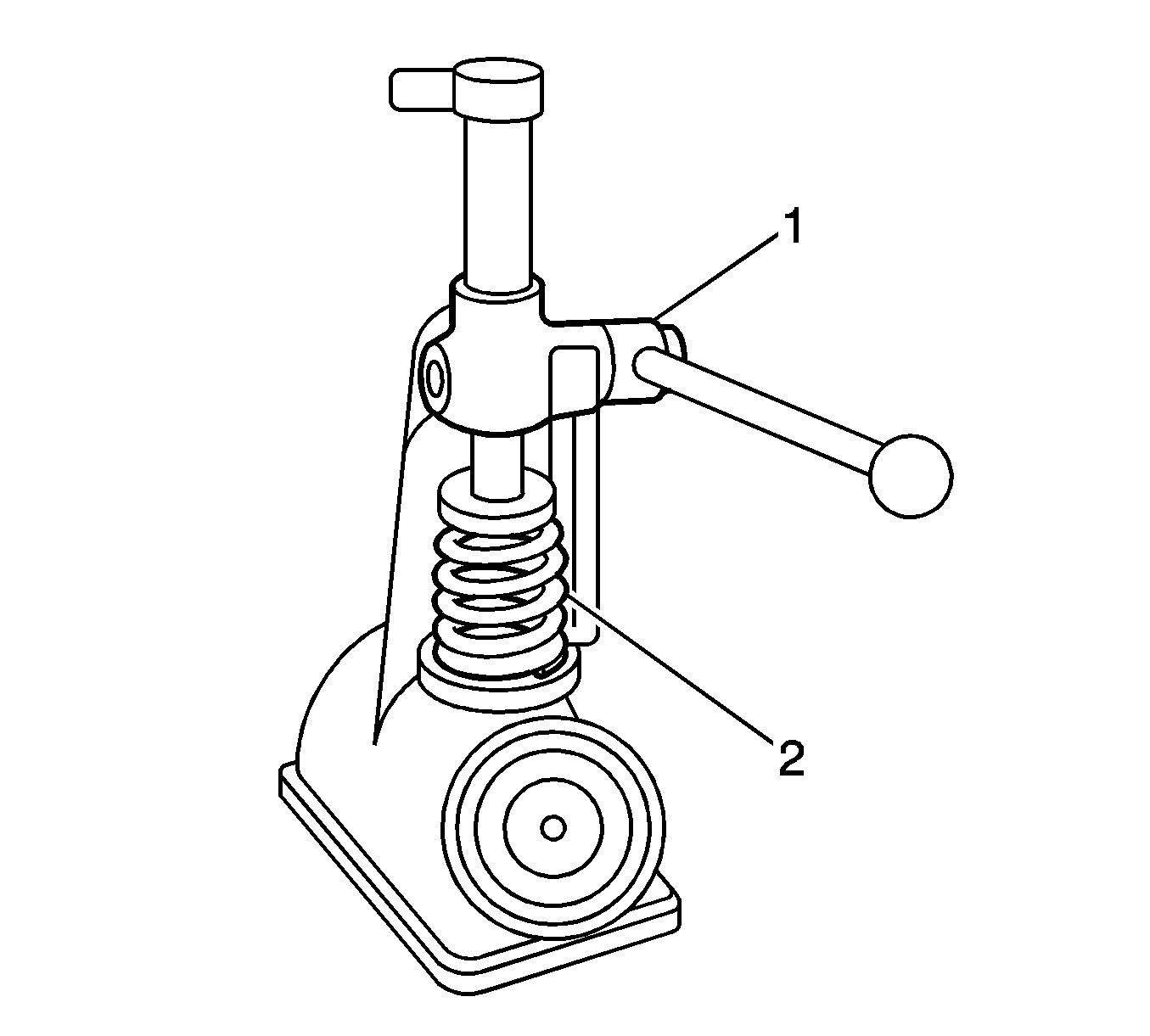
- Use a commercially available valve spring tester to measure the valve spring tension.
Important: Do not use shims to increase spring load. The use of shims can cause the valve spring to bottom out before the camshaft lobe is at peak lift.
- If low valve spring load is found, replace the valve springs.

