Special Tools
Removal Procedure
- Remove the Bank 1 secondary timing chain.
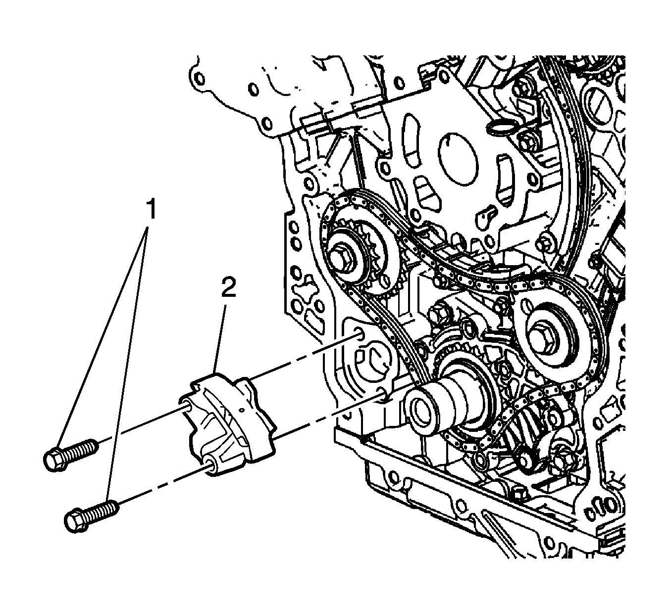
Important: Take care when removing the tensioner bolts. The tensioner plunger is subjected to spring tension and may spring apart during tensioner removal.
- Remove the 2 primary timing chain tensioner bolts (1), and remove the tensioner (2).
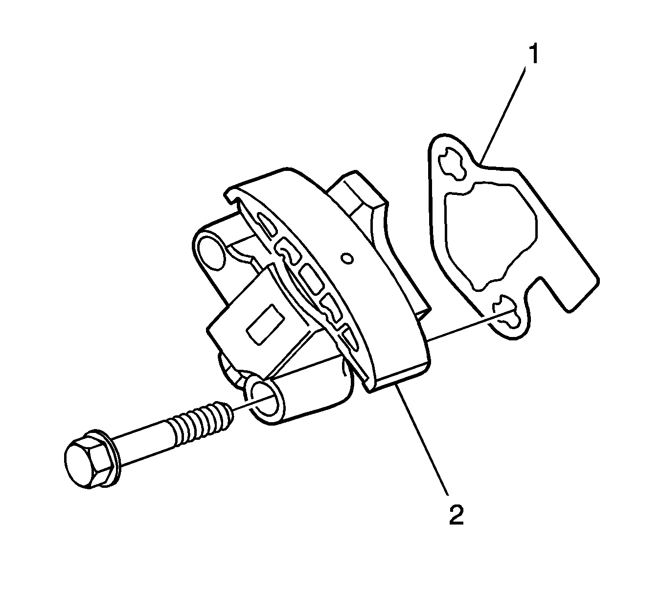
- Remove the gasket (1) from the tensioner (2) and discard the gasket.
- Inspect the primary timing chain tensioner mounting surface on the engine block for burrs or any defects that would affect the sealing of a new tensioner gasket.
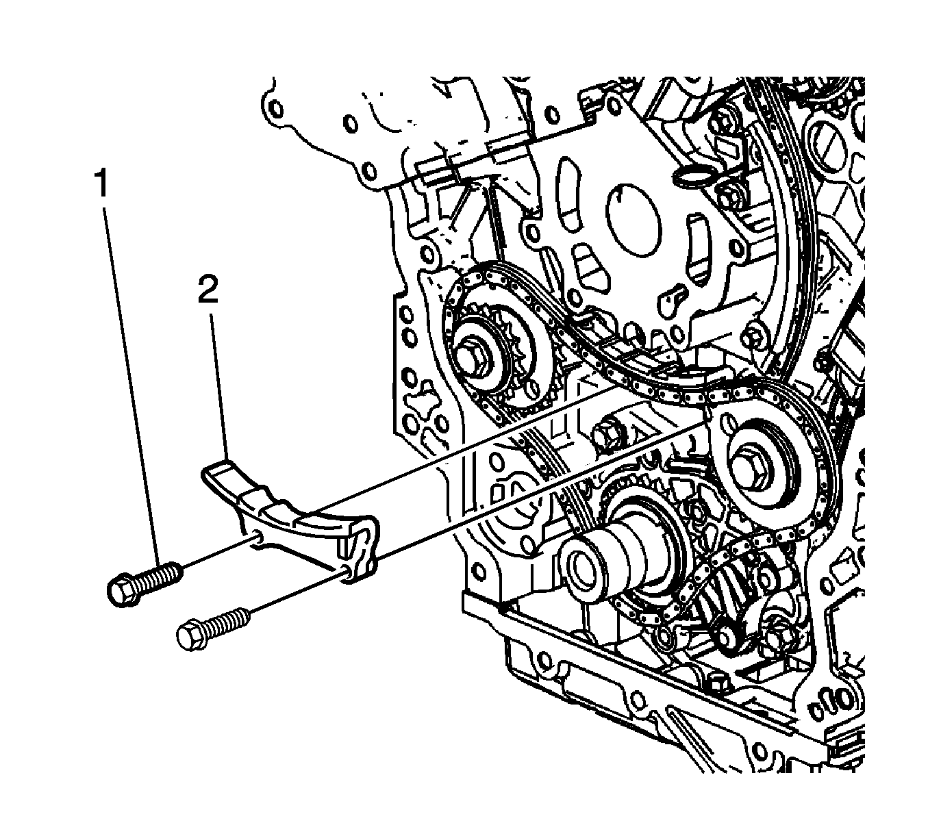
- Remove the 2 primary timing chain upper guide bolts (1) and remove the guide (2).
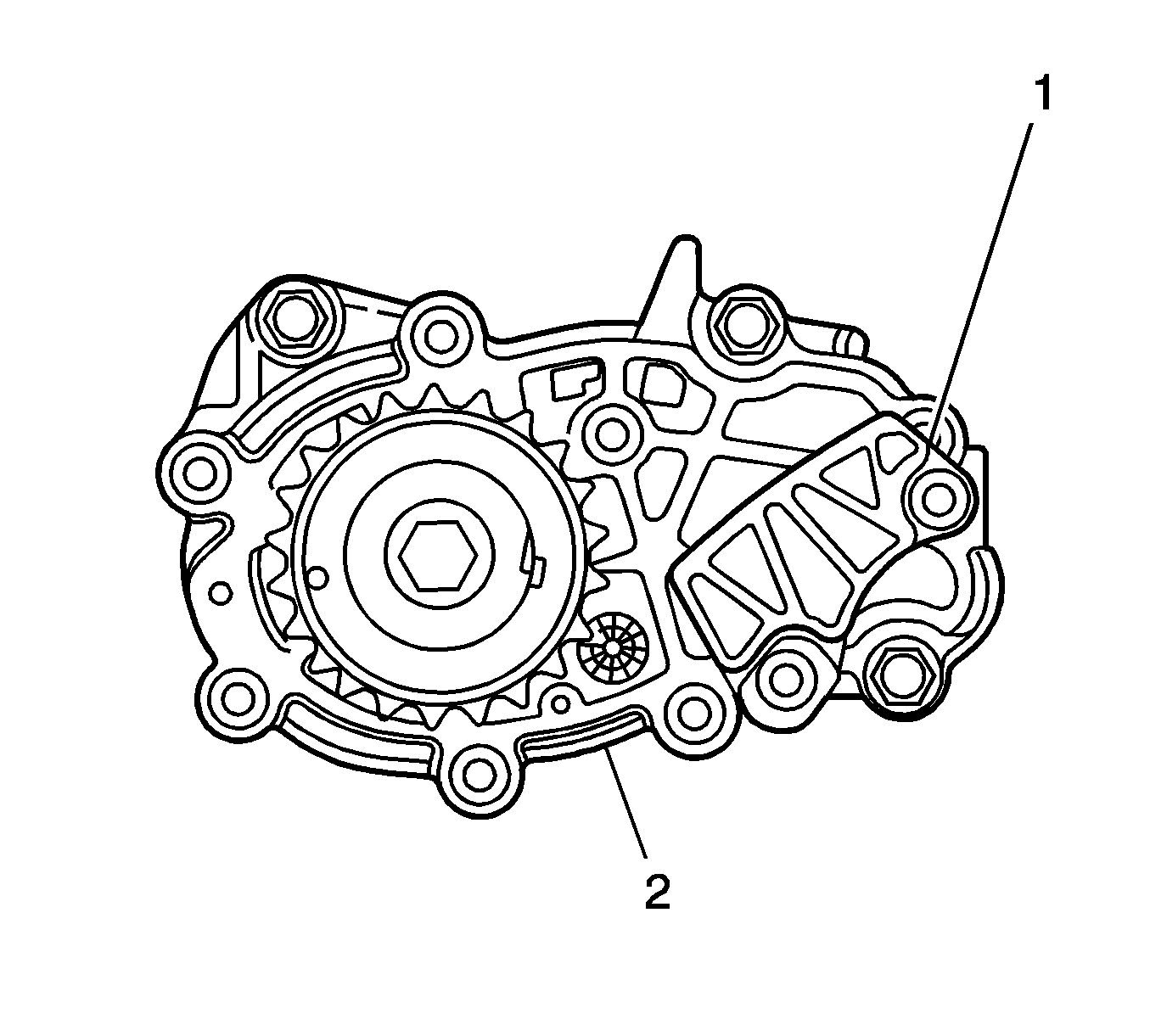
Important: Do not remove the primary timing chain lower guide (1). The primary timing chain lower guide is not serviced separately.
- If the primary timing chain lower guide requires replacement, the oil pump assembly (2) must be replaced.
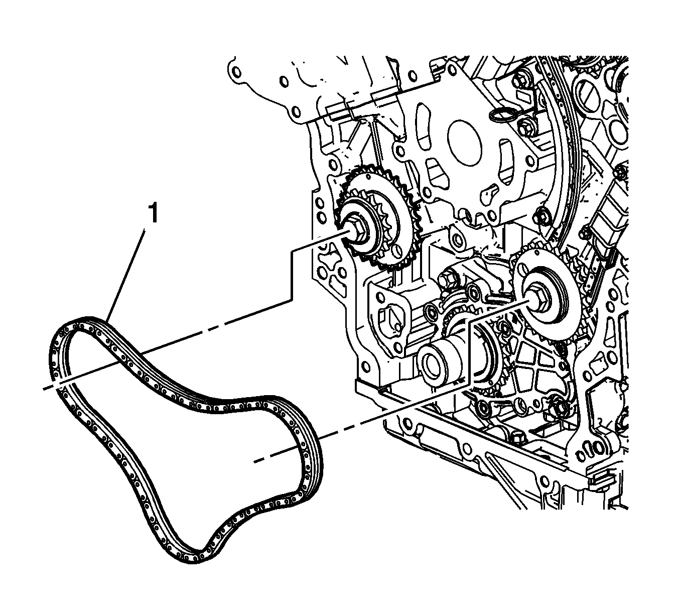
Important: For ease of removal, remove the chain from the crankshaft sprocket, before attempting to remove from the camshaft intermediate driveshaft sprockets.
- Remove the primary timing chain (1).
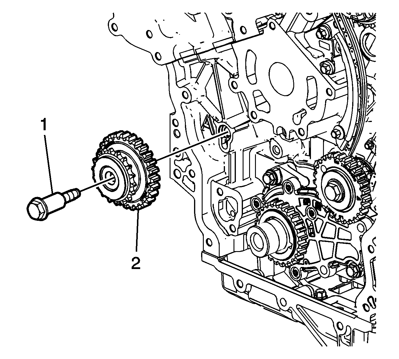
- If required, remove the bank 1 camshaft intermediate driveshaft sprocket bolt (1) and remove the sprocket (2).
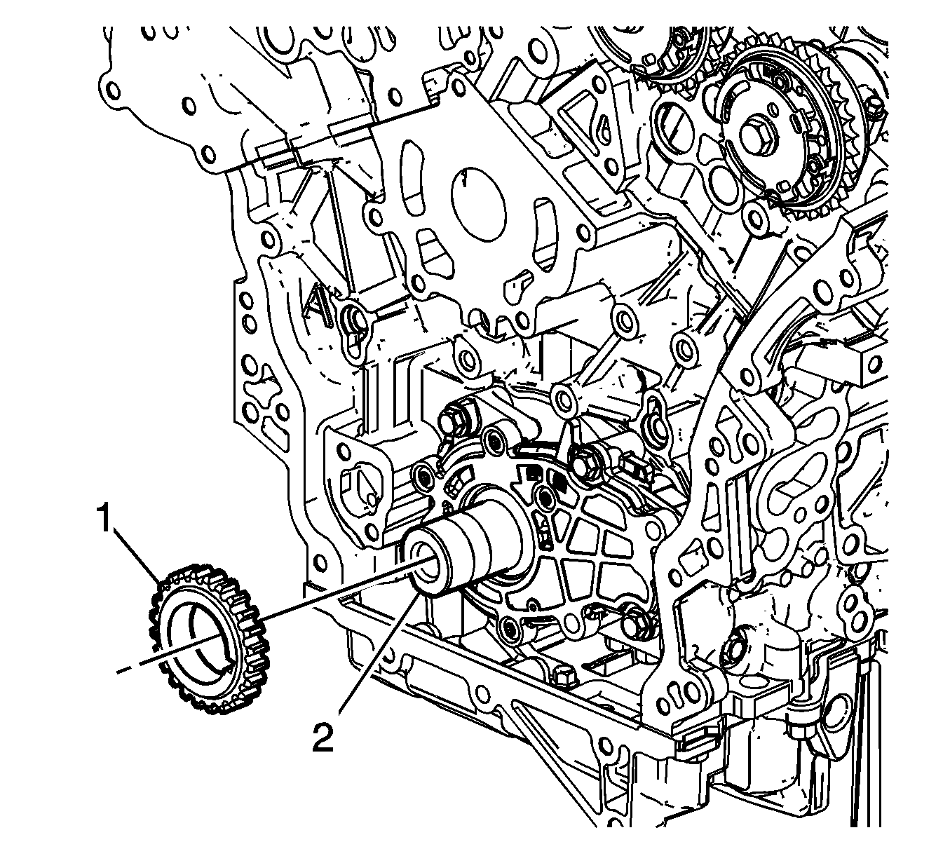
- If required, remove the crankshaft sprocket (1) from the crankshaft (2).
Cleaning Procedure
- Clean all the following components with a suitable solvent:
| • | Primary timing chain guide |
| • | Primary timing chain tensioner |
| • | Secondary timing chains |
| • | Secondary timing chain shoes |
| • | Secondary timing chain guides |
| • | Secondary timing chain tensioners |
- Dry all the components with compressed air.
Timing Chains Inspection
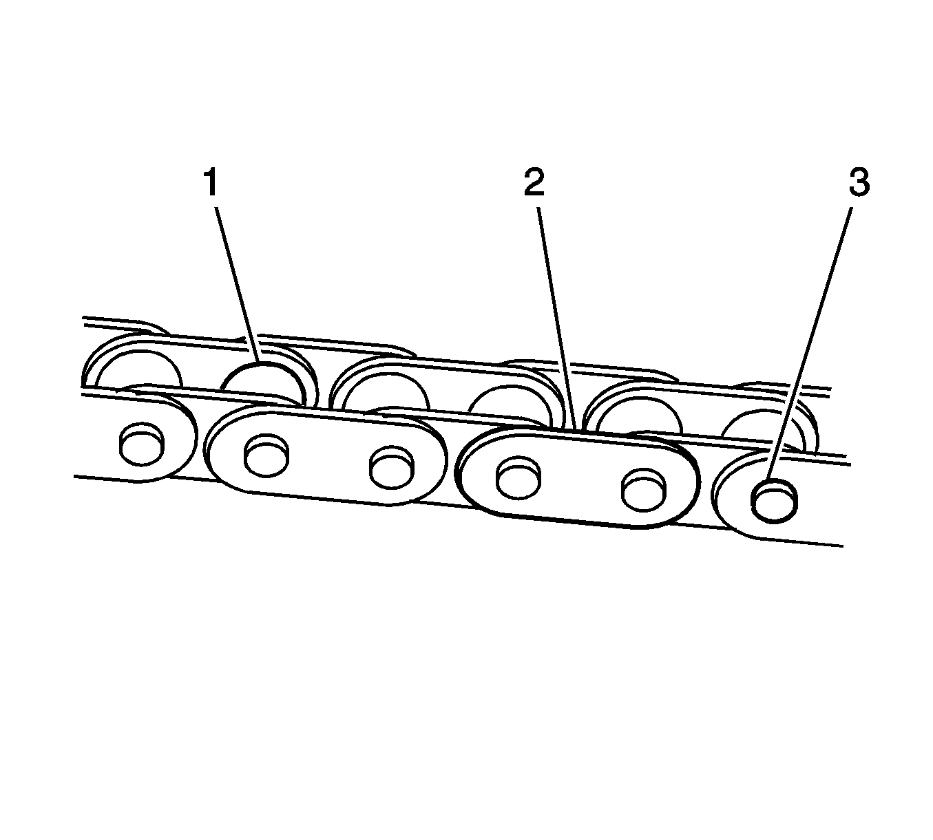
- Inspect the primary and/or secondary timing chains for the following:
| • | Binding or worn rollers (1) |
- Replace a damaged timing chain as required.
Camshaft Intermediate Driveshaft Sprockets Inspection
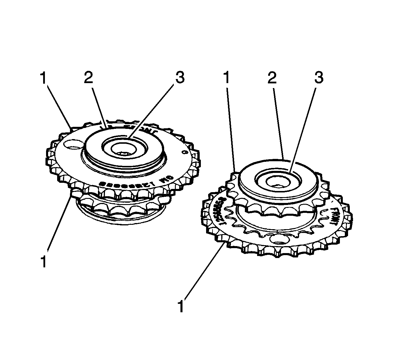
Inspect the camshaft intermediate driveshaft sprockets for the following:
| • | Damage to the primary and secondary timing chain sprocket (1). |
| • | Damage to the hub bearing (2). Ensure the hub bearing spins freely. If the hub bearing wobbles, is noisy or feels rough when rotated replace the camshaft intermediate sprocket. |
| • | Damage to the bolt flange seating/sealing surface (3). |
| • | Damage to the bearing hub-to-engine block sealing surface. |
| • | Inspect the camshaft position actuator assemblies. |
Crankshaft Sprockets Inspection
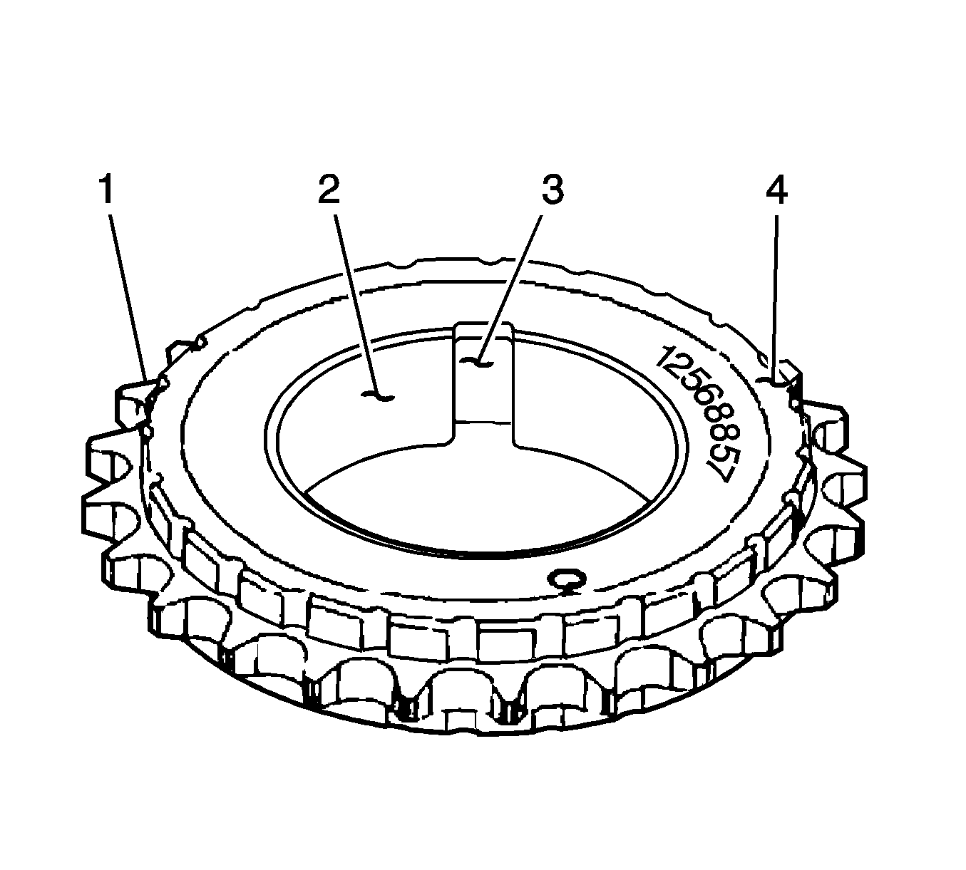
- Inspect the crankshaft sprocket for the following:
| • | Damage to the cushion material (4) |
- Replace a damaged sprocket as required.
Primary Timing Chain Upper Guide Inspection
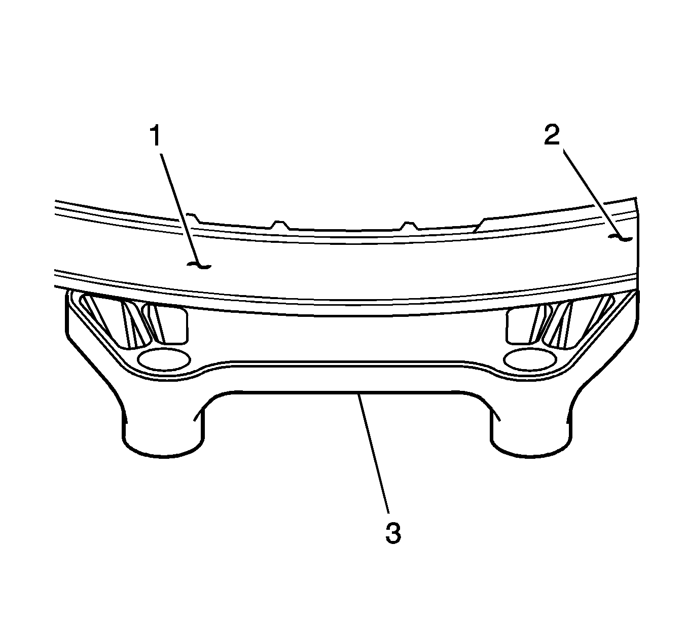
- Inspect the primary timing chain lower guide for the following:
| • | Cracked or broken guide surface (2) |
| • | Cracked or damaged guide base (3) |
- Replace a damaged guide as required.
Primary Timing Chain Lower Guide Inspection
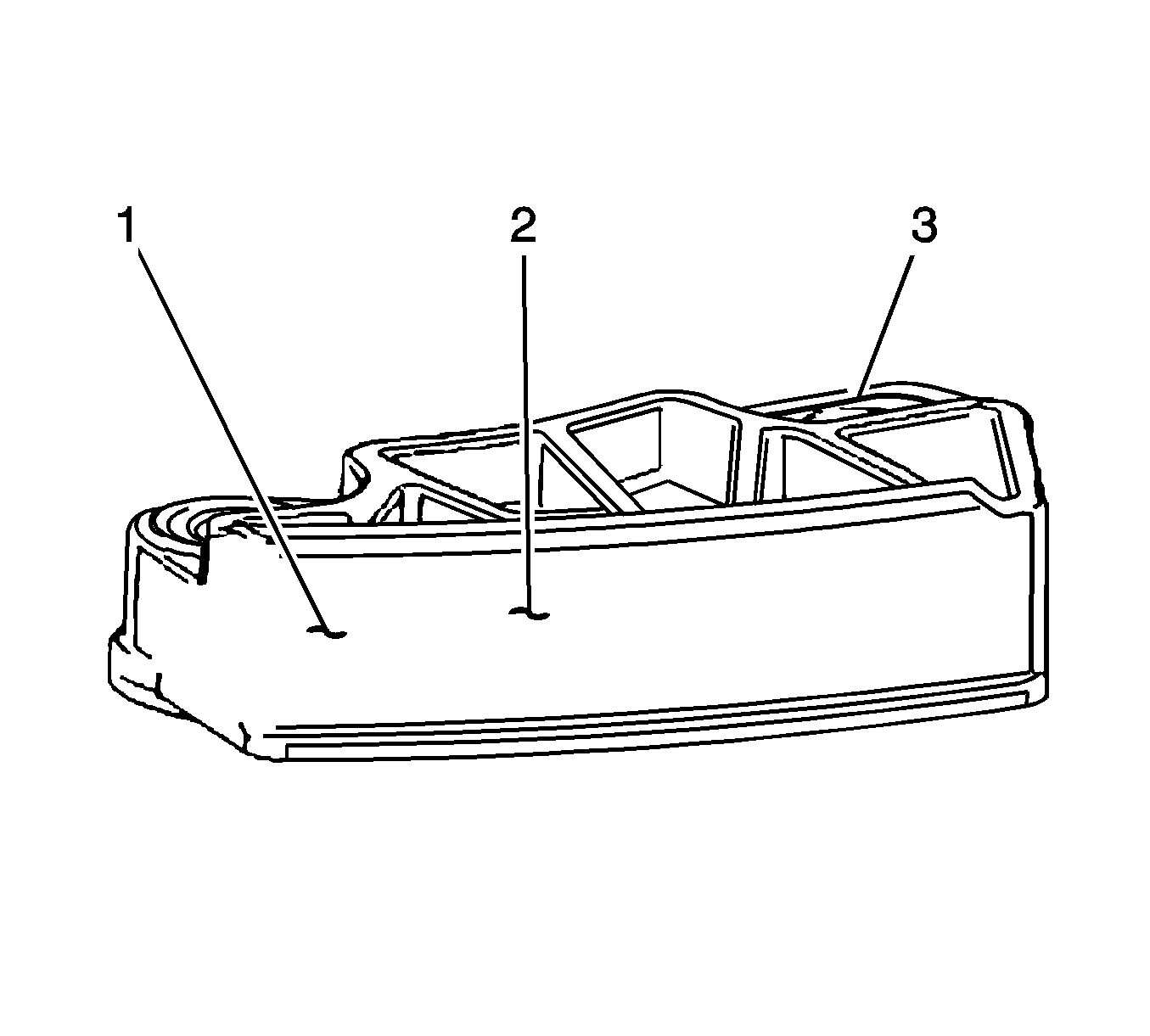
- Inspect the primary timing chain lower guide for the following:
| • | Cracked or broken guide surface (2) |
| • | Cracked or damaged guide base (3) |
Important: The primary timing chain lower guide is not serviced separately and is part of the oil pump assembly.
- Replace the primary timing chain lower guide by replacing the oil pump assembly, if necessary. Refer to
Oil Pump Replacement .
Primary Timing Chain Tensioner Inspection
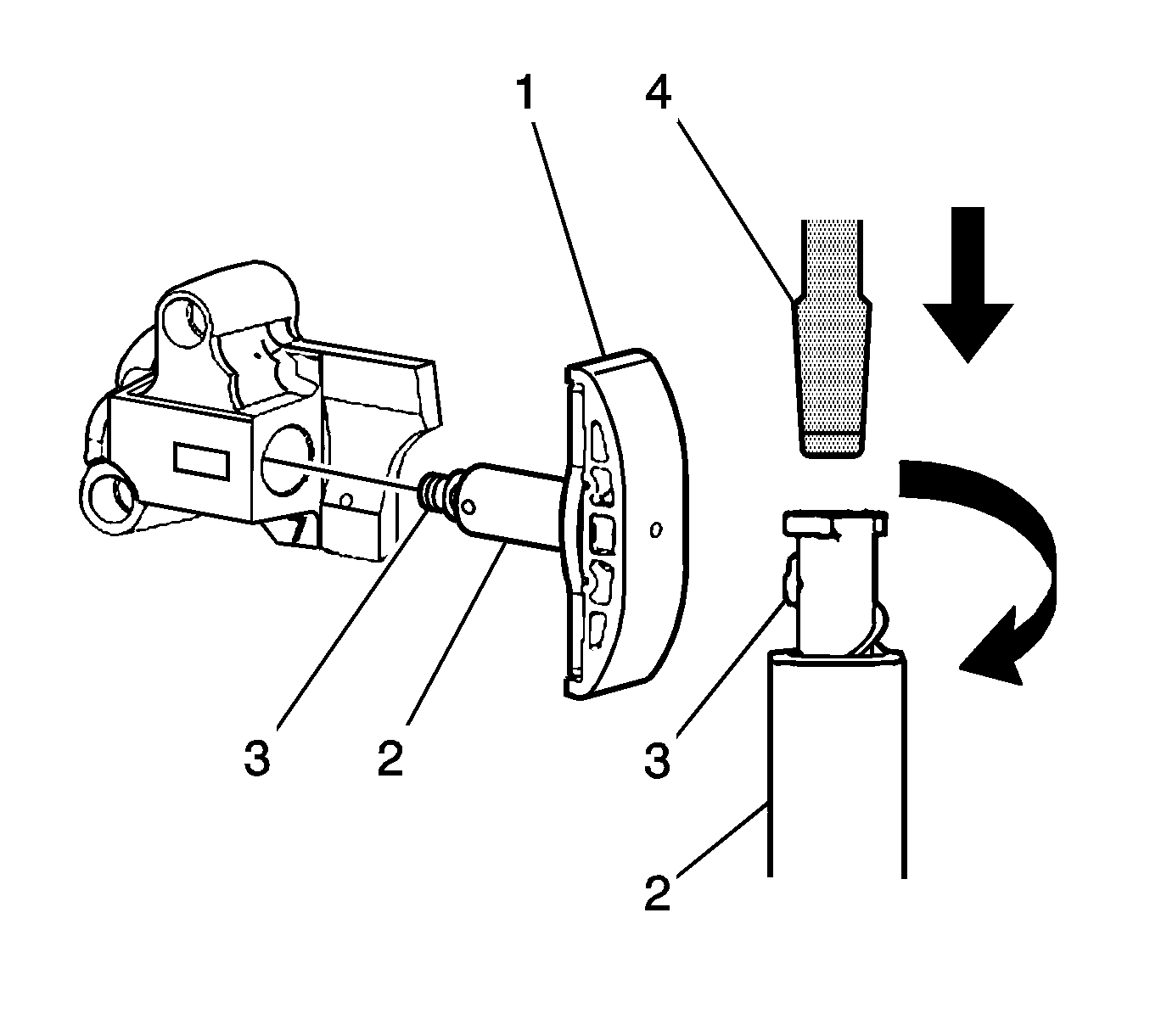
- Inspect the primary timing chain tensioner for worn shoe surface (1).
- Inspect the tensioner for a locked or binding tensioner shaft (2). Reset the plunger (3) and ensure the tensioner shaft moves freely in and out of the body of the tensioner
Important: To reset the tensioner, use a suitably sized flat-bladed screwdriver (4) to wind the plunger in a clockwise direction, into the tensioner shaft.
- Replace a damaged tensioner as required.
Bank 2 Secondary Timing Chain Guide Inspection
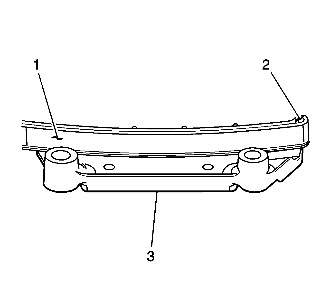
- Inspect the bank 2 secondary timing chain guide for the following:
| • | Cracked or broken guide surface (2) |
| • | Cracked or damaged guide (3) |
- Replace a damaged guide as required. Reset the plunger (3) and ensure the tensioner shaft moves freely in and out of the body of the tensioner.
Bank 2 Secondary Timing Chain Shoe Inspection
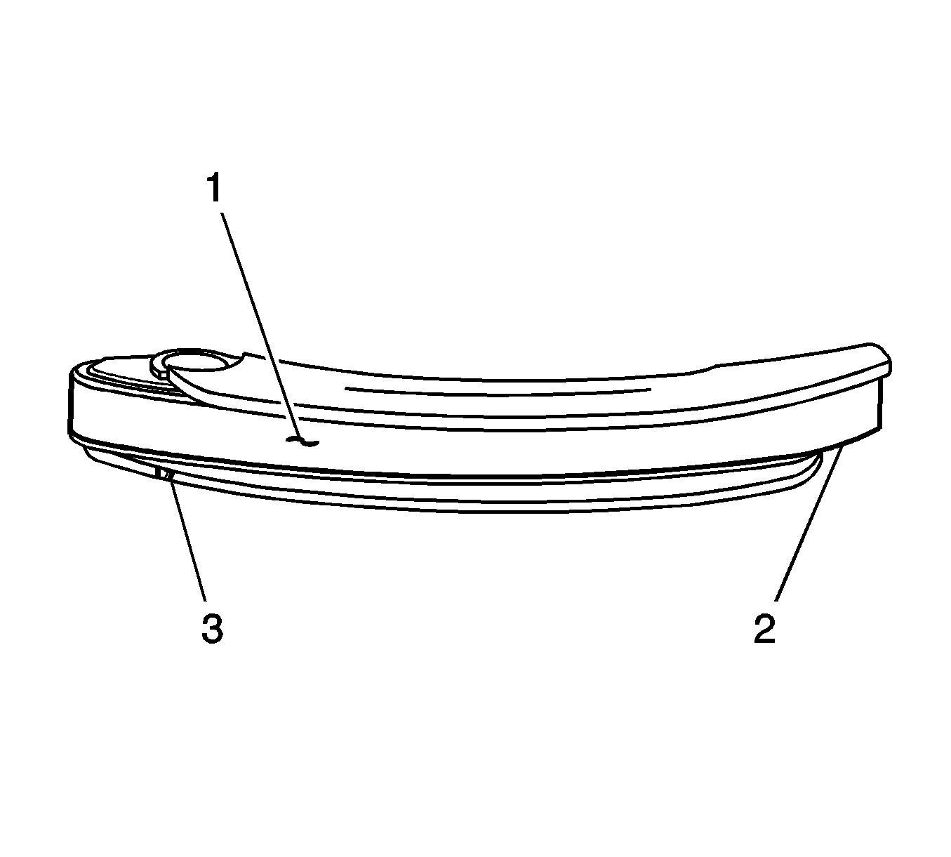
- Inspect the front of the bank 2 secondary timing chain shoe for the following:
| • | Cracked or broken shoe surface (2) |
| • | Cracked or damaged shoe (3) |
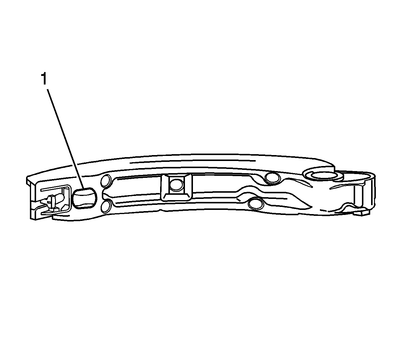
- Inspect the back of the shoe for a damaged, worn or missing timing chain tensioner contact pad (1).
- Replace a damaged shoe as required.
Bank 2 Secondary Timing Chain Tensioner Inspection
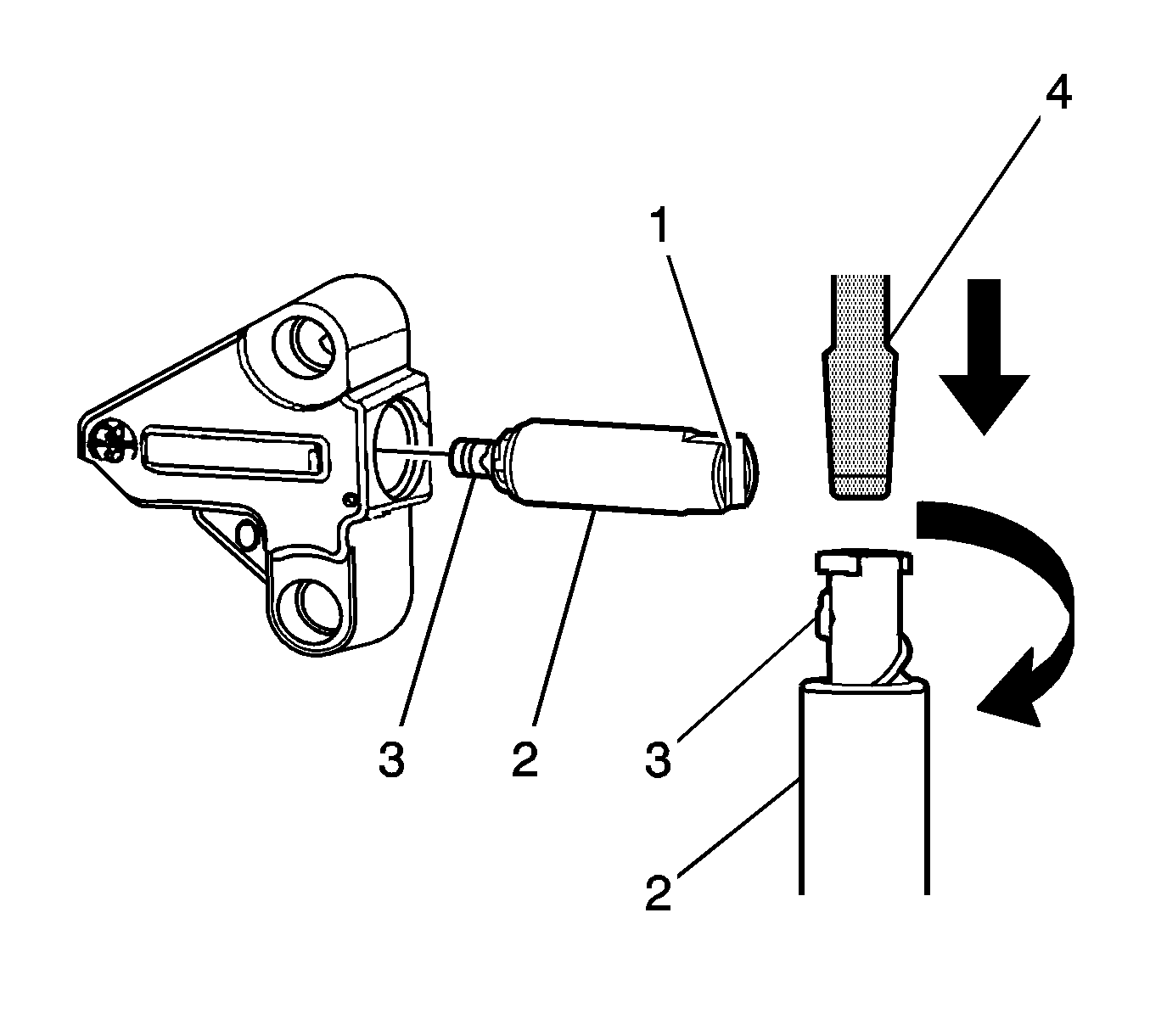
- Inspect the bank 2 secondary timing chain tensioner for damaged plunger-to-shoe contact surface (1).
- Inspect the tensioner for locked or binding tensioner shaft (2). Reset the plunger (3) and ensure the tensioner shaft moves freely in and out of the body of the tensioner.
Important: To reset the tensioner, use a suitably sized flat-bladed screwdriver (4) to wind the plunger in a clockwise direction, into the tensioner shaft.
- Replace a damaged tensioner as required.
Bank 1 Secondary Timing Chain Guide Inspection
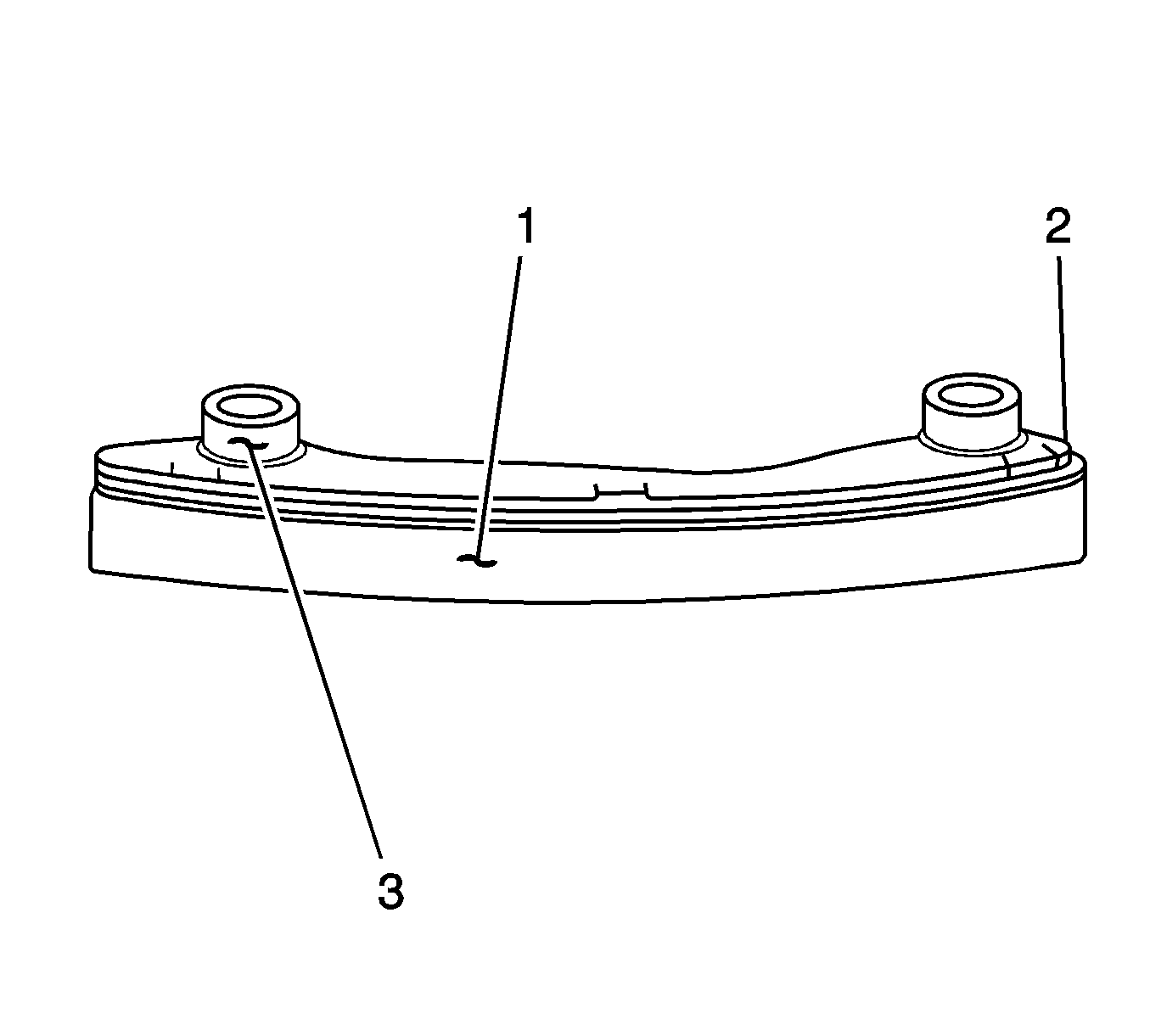
- Inspect the bank 1 secondary timing chain guide for the following:
| • | Cracked or broken guide surface (2) |
| • | Cracked or damaged guide base (3) |
- Replace a damaged guide as required.
Bank 1 Secondary Timing Chain Shoe Inspection
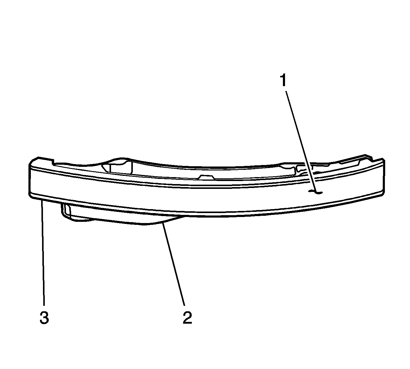
- Inspect the front of the bank 1 secondary timing chain shoe for the following:
| • | Cracked or broken shoe surface (2) |
| • | Cracked or damaged shoe (3) |
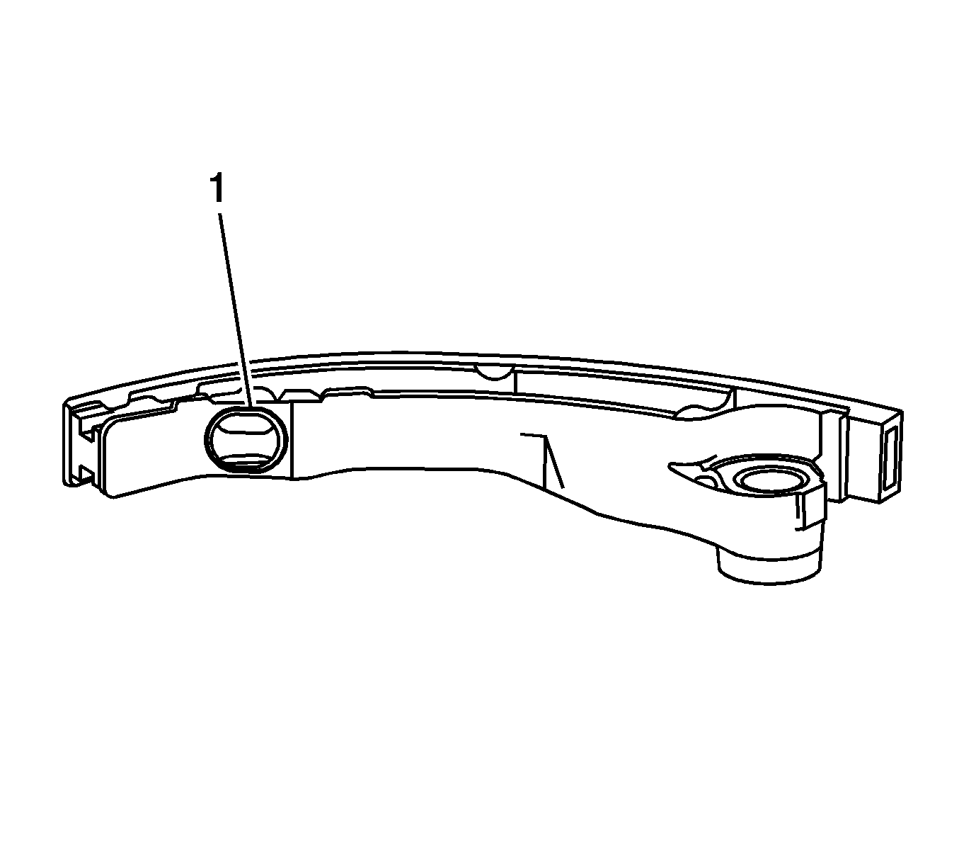
- Inspect the back of the shoe for a damaged, worn or missing timing chain tensioner contact pad (1).
- Replace a damaged shoe as required.
Bank 1 Secondary Timing Chain Tensioner Inspection
- Inspect the bank 1 secondary timing chain tensioner for damaged plunger-to-shoe contact surface (1).
Important: To reset the tensioner, use a suitably sized flat-bladed screwdriver (4) to wind the plunger in a clockwise direction, into the tensioner shaft.
- Inspect the tensioner for a locked or binding tensioner shaft (2). Reset the plunger (3) and ensure the tensioner shaft moves freely in and out of the body of the tensioner.
- Replace a damaged tensioner as required.
Installation Procedure
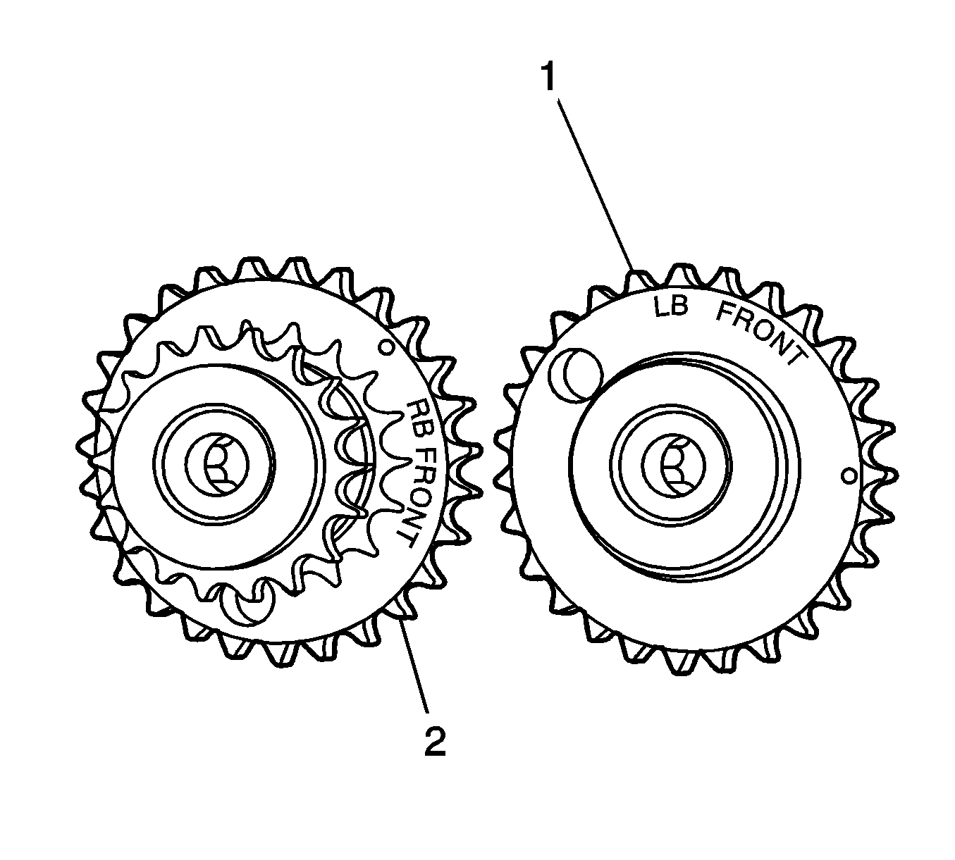
- If previously removed, install the bank 2 secondary timing chain components.
Important: The bank 1 camshaft intermediate drive-shaft sprocket (2) is marked with the letters RB and ’FRONT’, and the bank 2 sprocket (1) is marked with the letters LB and ’FRONT’ ensure the
correct sprocket is used and the FRONT text is facing forwards when installed.
- Ensure the bank 1 camshaft intermediate driveshaft sprocket is selected and orientated correctly.
Notice: Refer to Fastener Notice in the Preface section.

- Install the bank 1 camshaft intermediate driveshaft sprocket (2).
Tighten
Tighten the bank 1 camshaft intermediate driveshaft sprocket attaching bolt to 65 N·m (48 lb ft).
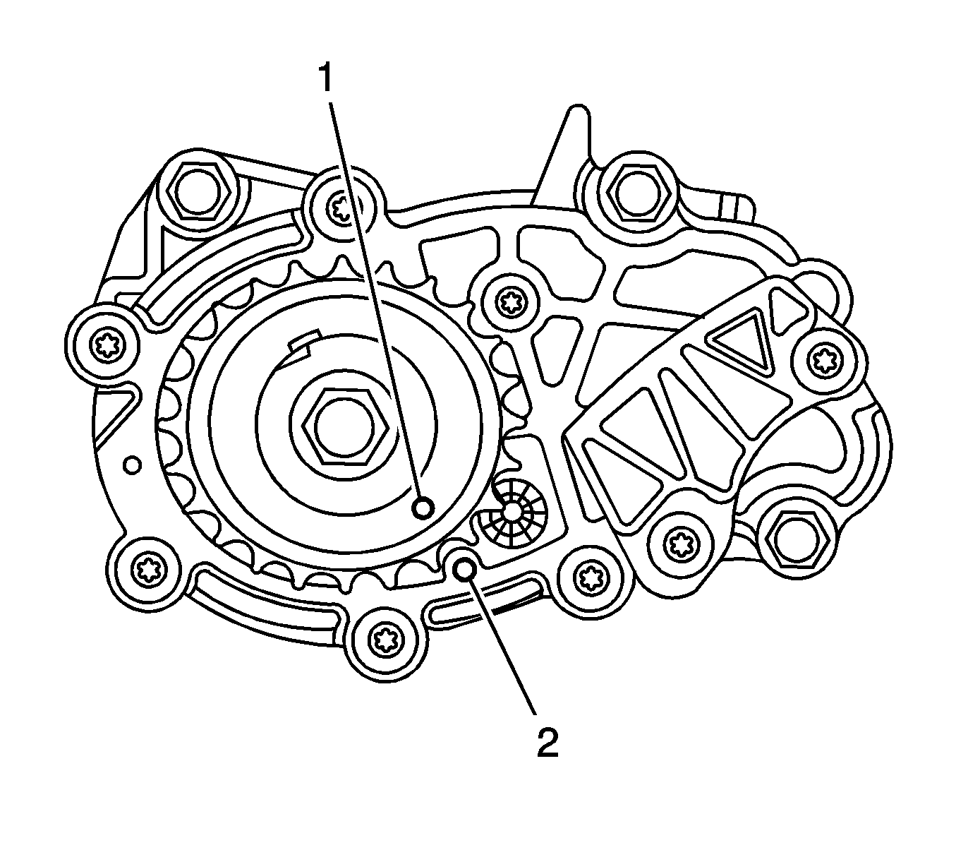
- Ensure that the crankshaft sprocket timing mark (1) is aligned with the indexing mark (2) on the oil pump housing.

- Install the primary timing chain (1).
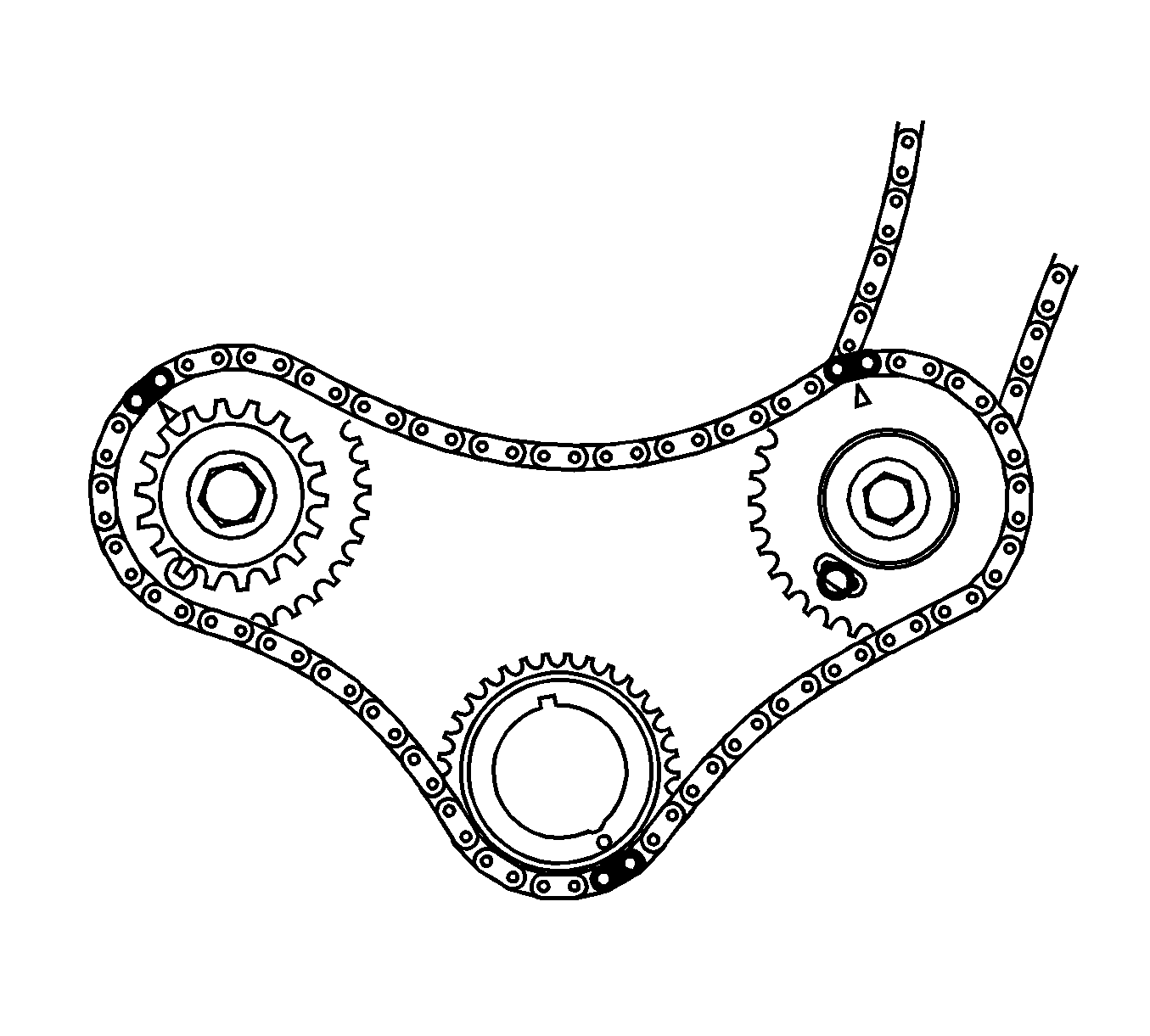
- Wrap the primary timing chain around the large sprockets of each camshaft intermediate driveshaft sprocket and the crankshaft sprocket aligning the brightened chain links.
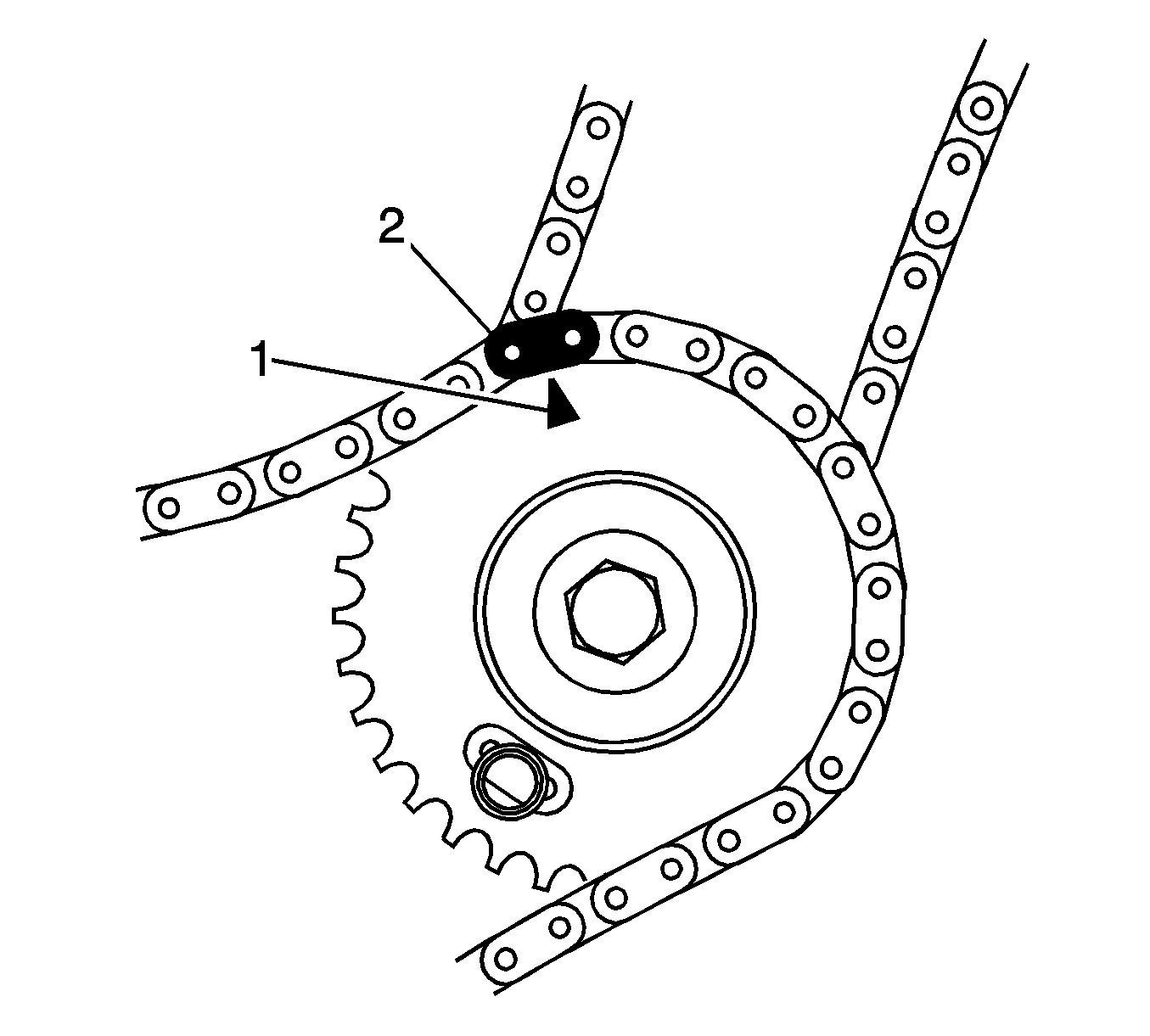
- The bank 2 camshaft intermediate driveshaft sprocket timing mark (1) will align with a bright plated primary timing chain link (2).
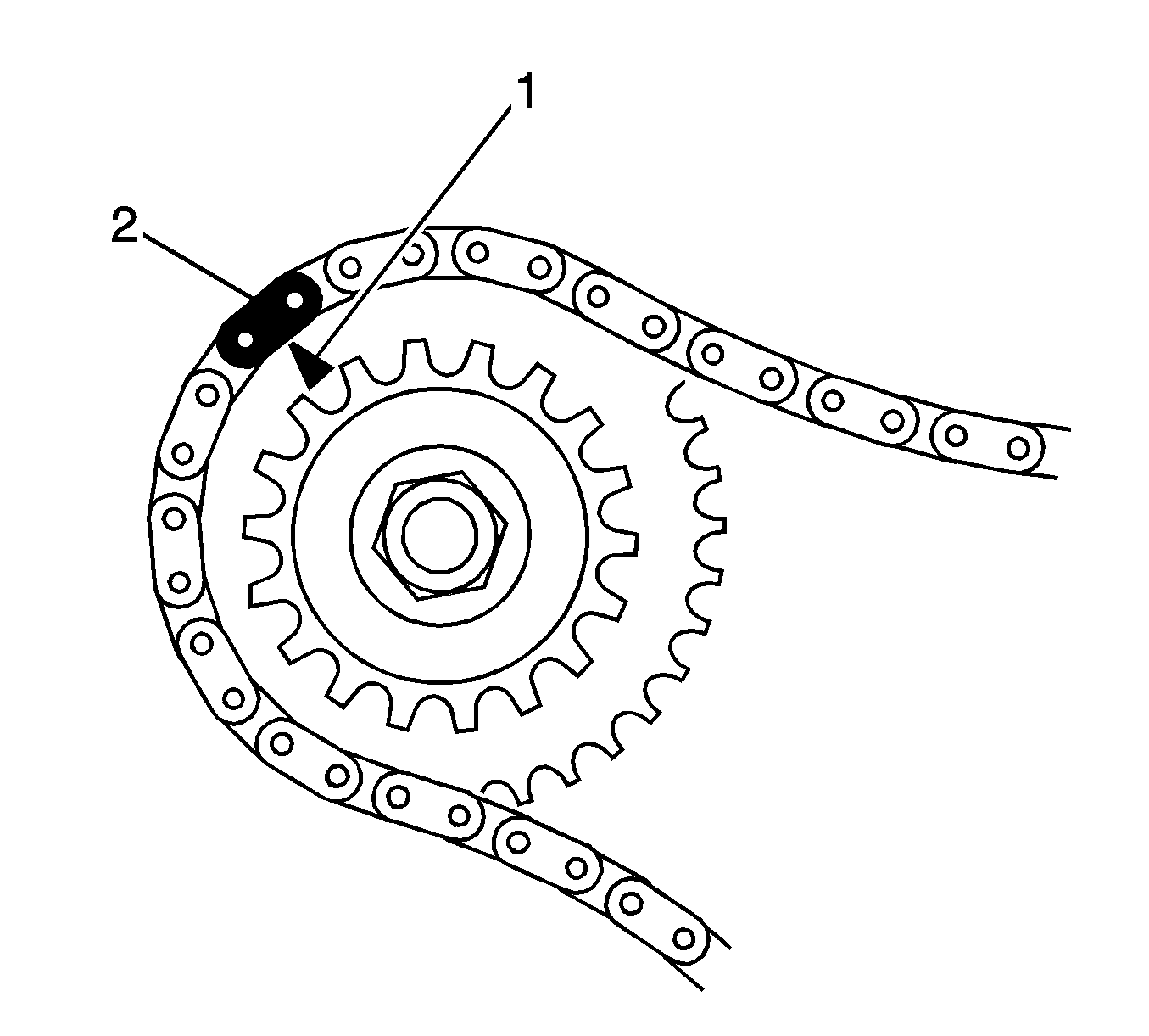
- The bank 1 camshaft intermediate driveshaft sprocket timing mark (1) will align with a bright plated primary timing chain link (2).
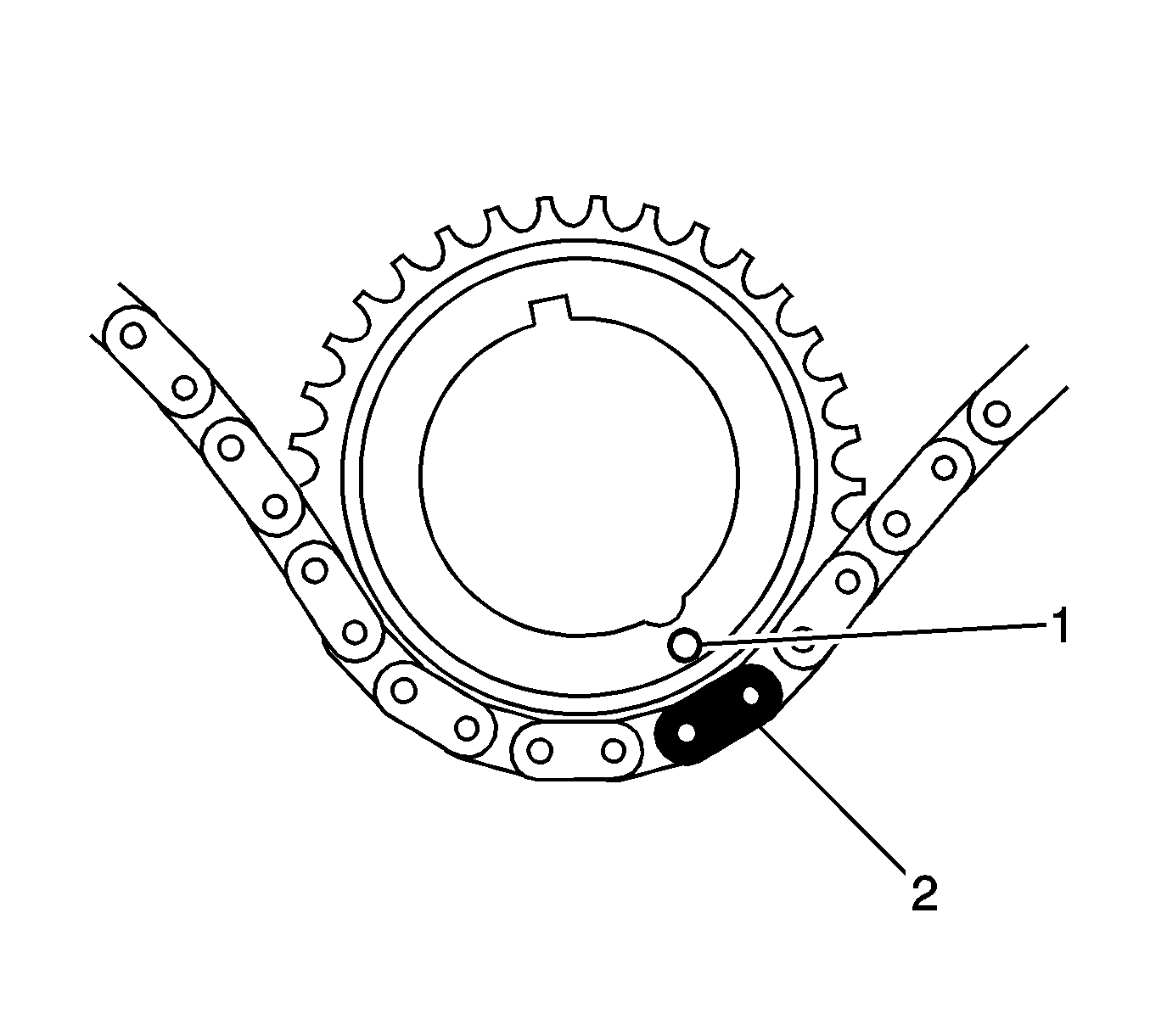
- The crankshaft sprocket timing mark (1) will align with a bright plated timing chain link (2).
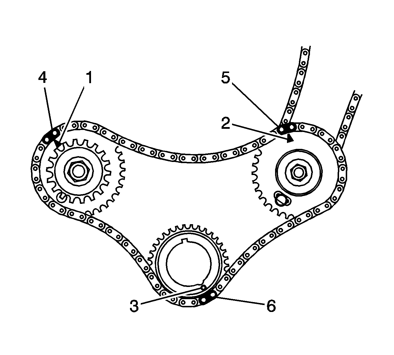
- Ensure all the timing marks (1, 2 and 3) are properly aligned with the bright plated timing chain links (4, 5 and 6).
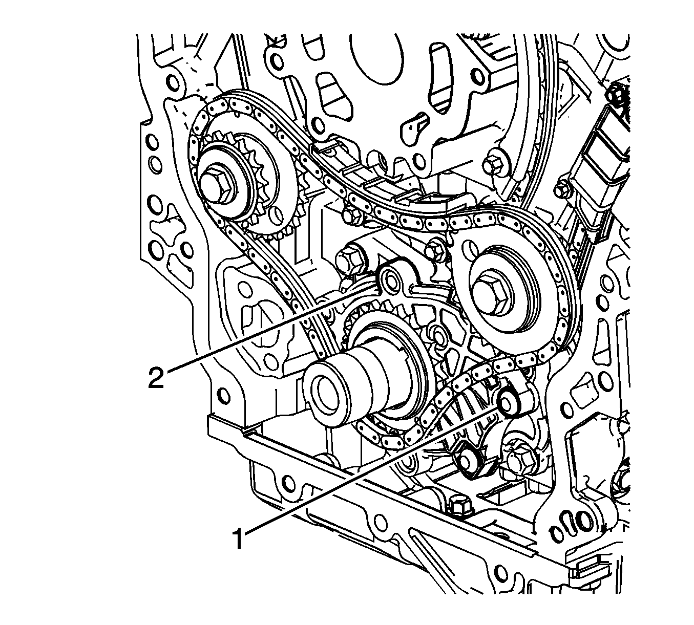
- Do not remove the primary timing chain lower guide (1). The primary timing chain lower guide is not serviced separately. If the primary timing chain lower guide must be replaced, the oil pump assembly (2) must be
replaced.
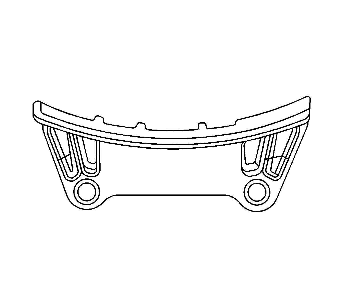
- Ensure the primary timing chain upper guide is selected and orientated correctly.

- Install the primary timing chain upper guide (1).
- Install the primary timing chain upper guide bolts (2).
Tighten
Tighten the primary timing chain upper guide bolts to 23 N·m (17 lb ft).
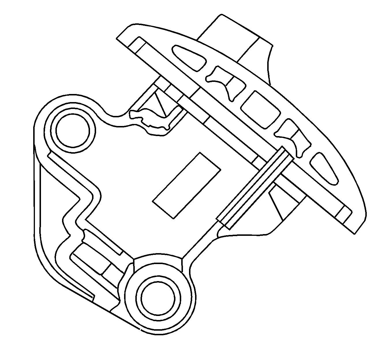
- Ensure that the primary timing chain tensioner is being installed.
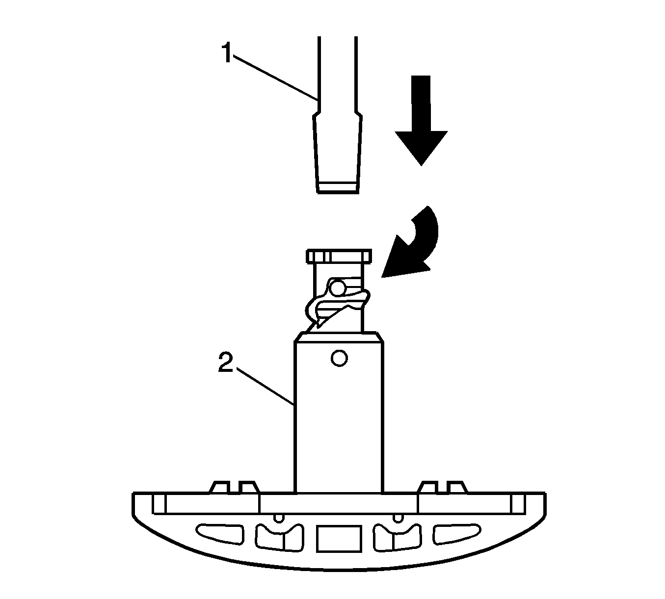
Important: To reset the tensioner, use a suitably sized flat-bladed screwdriver (1) to wind the plunger in a clockwise direction, into the tensioner shaft (2) .
- Reset the primary timing chain tensioner.
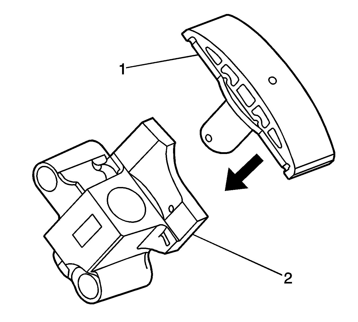
- Install the tensioner shoe assembly (1) into the primary timing chain tensioner body (2).
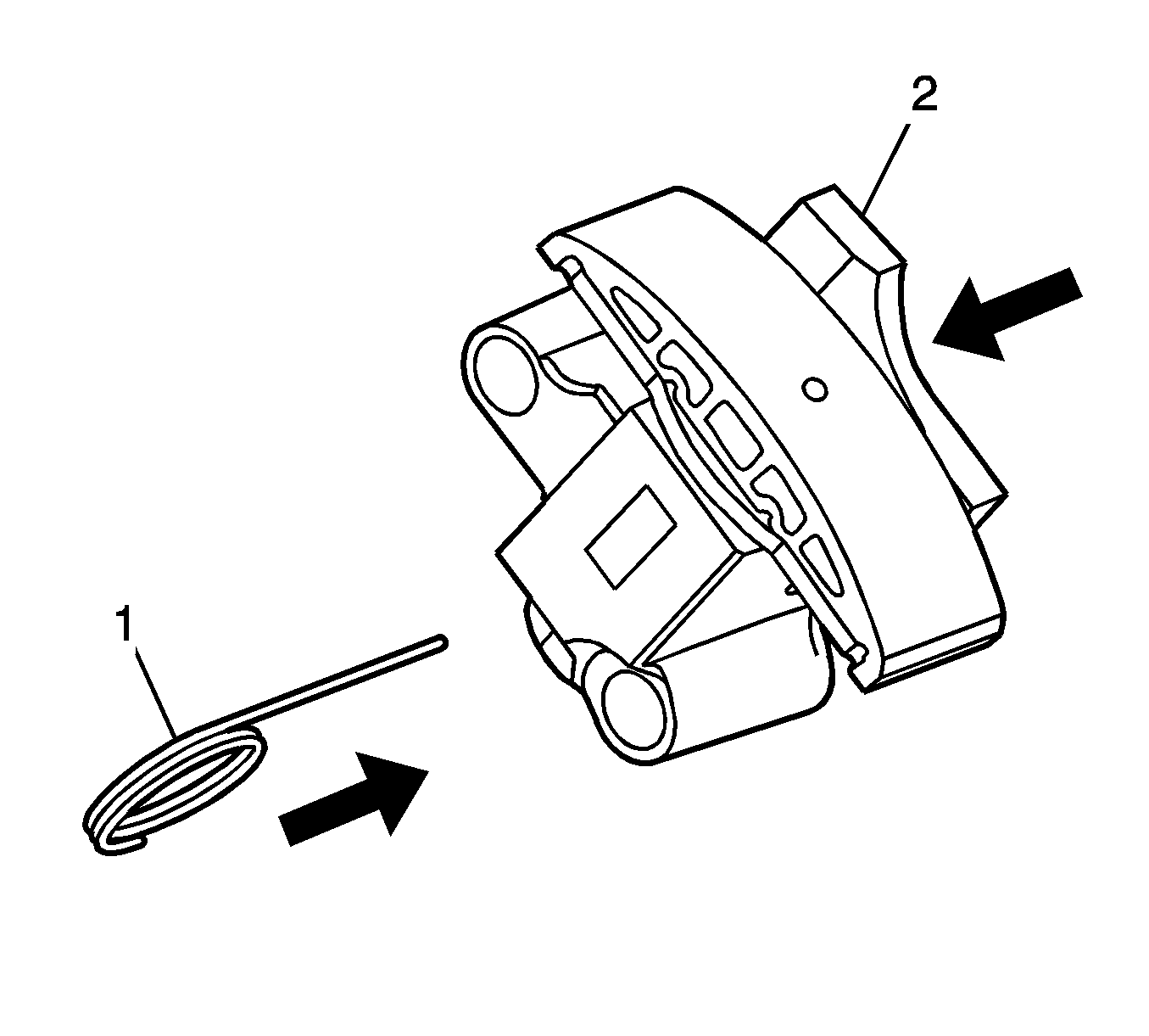
Important: If
EN 46112 (1) is not inserted into the tensioner body, the plunger will remain in the locked position and no tension will be placed on the timing chain.
- Compress the shoe assembly into the body (2) and lock the primary timing chain tensioner by inserting
EN 46112 into the access hole in the side of the body.
- Slowly release pressure on the primary timing chain tensioner. The primary timing chain tensioner should remain compressed.
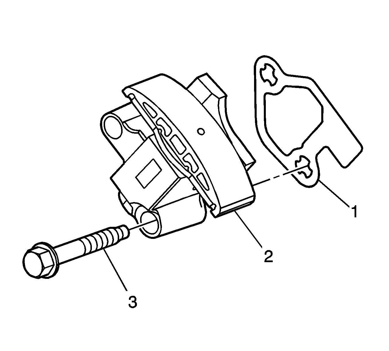
- Install a new primary timing chain tensioner gasket (1) to the tensioner (2).
- Install the primary timing chain tensioner bolts (3) through tensioner and gasket.
- Ensure the primary timing chain tensioner mounting surface on the engine block does not have any burrs or defects that would affect the sealing of the new gasket.

- Place the primary timing chain tensioner (2) into position and loosely install the bolts (1) to the engine block.
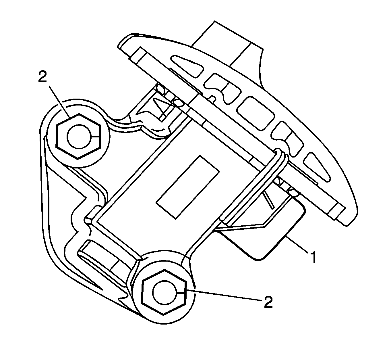
- Verify the proper placement of the primary timing chain tensioner gasket tab (1).
- Tighten the primary timing chain tensioner bolts (2).
Tighten
Tighten the primary timing chain tensioner bolts to 23 N·m (17 lb ft).
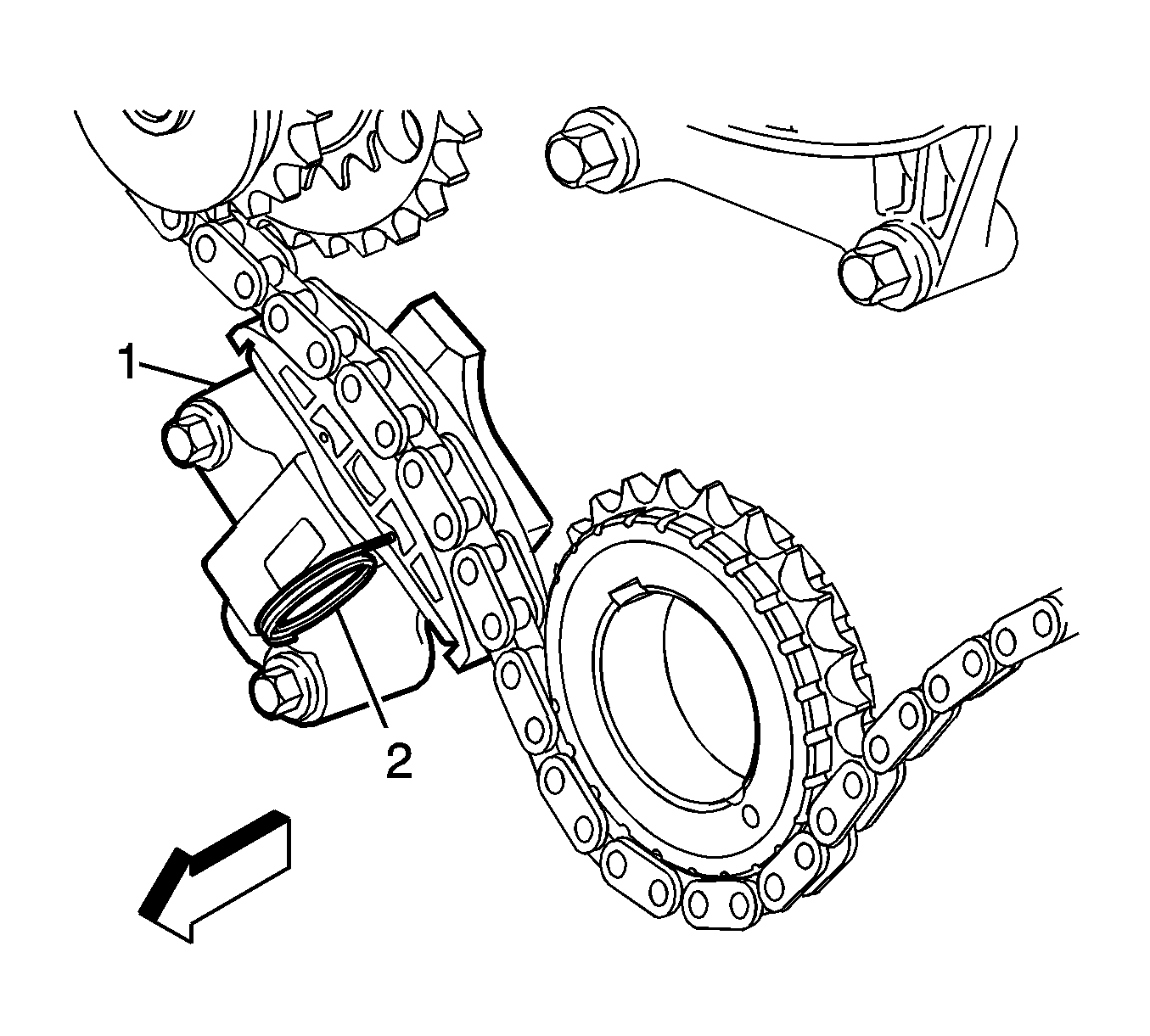
- Release the primary timing chain tensioner (1) by pulling out
EN 46112 (2) and unlocking the tensioner shaft.
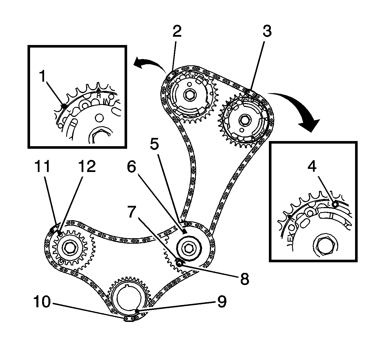
- Verify the primary and bank 2 secondary timing chain timing mark alignments (1-12).
- Remove
EN 46105 from bank 2 and bank 1 cylinder head camshafts.


