Caution: Refer to Brake Dust Caution in the Preface section.
Removal Procedure
General Motors replacement brake lining material is recommended for all vehicles in order to maintain the balance between the front and the rear brake performance.
General Motors replacement brake parts have been carefully selected in order to provide the following of the proper conditions:
| • | Brake balance |
| • | Stopping distance |
| • | Brake control over the full range of operating conditions |
Installation of the front/rear brake lining materials unequal to the GM replacement parts recommended for this vehicle can change the proper brake balance.
- Block the wheels.
- Cage the rear air brake chambers. Refer to Caging the Rear Air Brake Chamber .
- Drain all air reservoirs. Refer to Air Brake Reservoir Draining .
- Raise and support the vehicle. Refer to Lifting and Jacking the Vehicle .
- Remove the tire and the wheel assemblies. Refer to Tire and Wheel Removal and Installation .
- Remove the brake drums. Refer to Brake Drum Replacement .
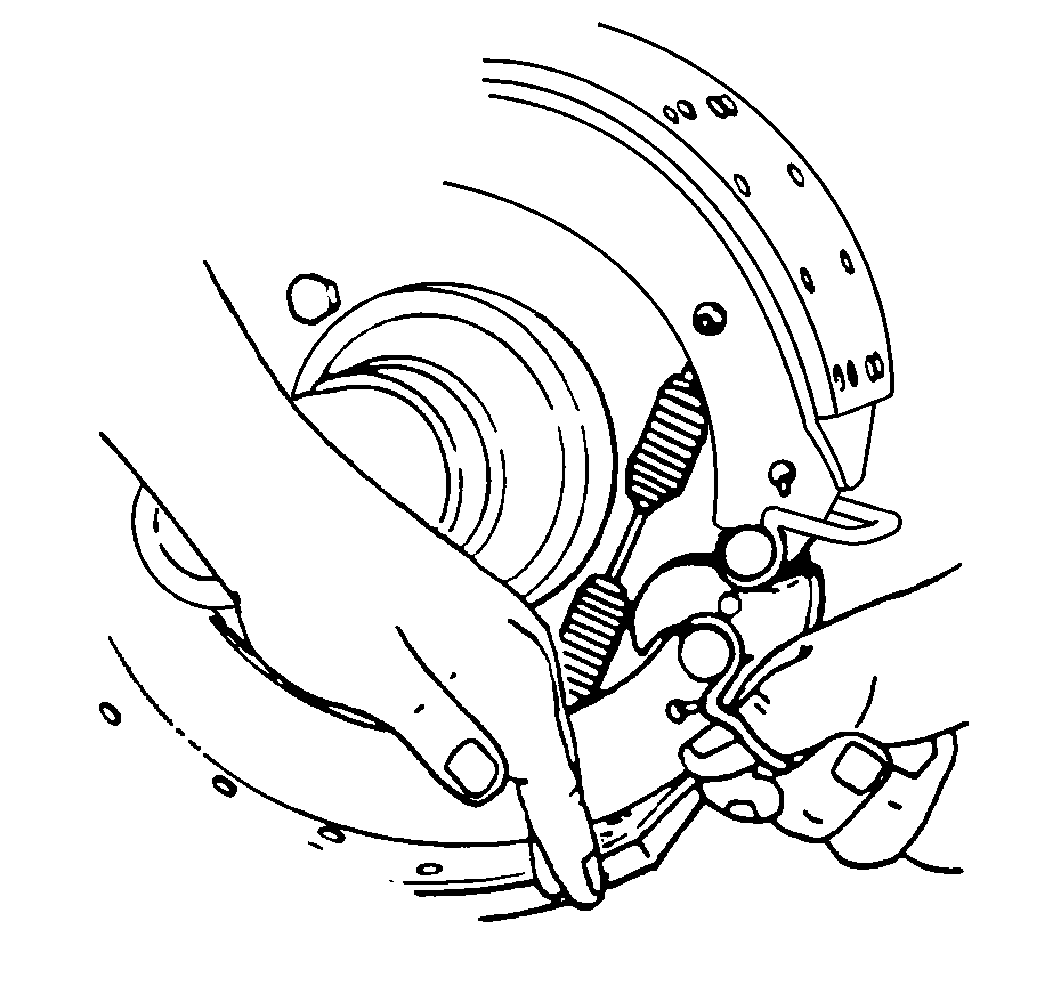
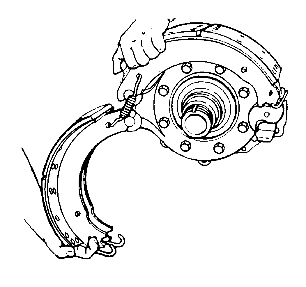
- Push down on the bottom brake shoe.
- Pull on the brake shoe roll retainer in order to remove the bottom brake shoe roller.
- Lift the bottom brake shoe in order to release the tension on the brake shoe return spring.
- Remove the brake shoe return spring.
- Rotate the bottom brake shoe in order to release the tension on the 2 retaining springs.
- Remove the retaining springs.
- Remove the brake shoes.
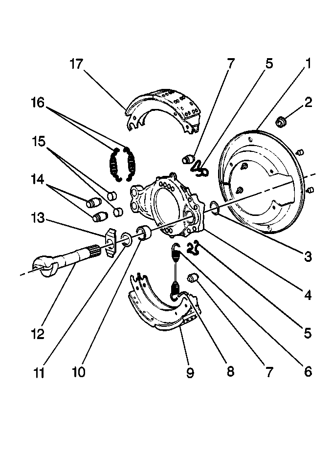
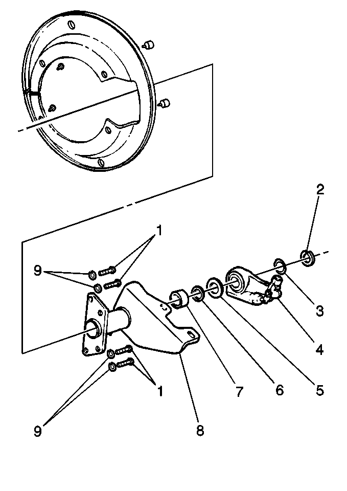
- Inspect the brake spider (4) for expanded anchor pin holes and for cracks. Replace the damaged brake spiders (4) and the anchor pin bushings (15).
- Inspect the brake chamber/camshaft support bracket (8) for broken welds, cracks, and correct alignment. Replace the damaged brake chamber/camshaft support brackets (8).
- Inspect the anchor pins (14) for corrosion and wear. Replace the damaged anchor pins (14).
- Inspect the camshaft (12) for cracks, wear, and corrosion. Replace the damaged camshafts (12).
- Inspect the air drums. Refer to Air Drum Brake System Inspection .
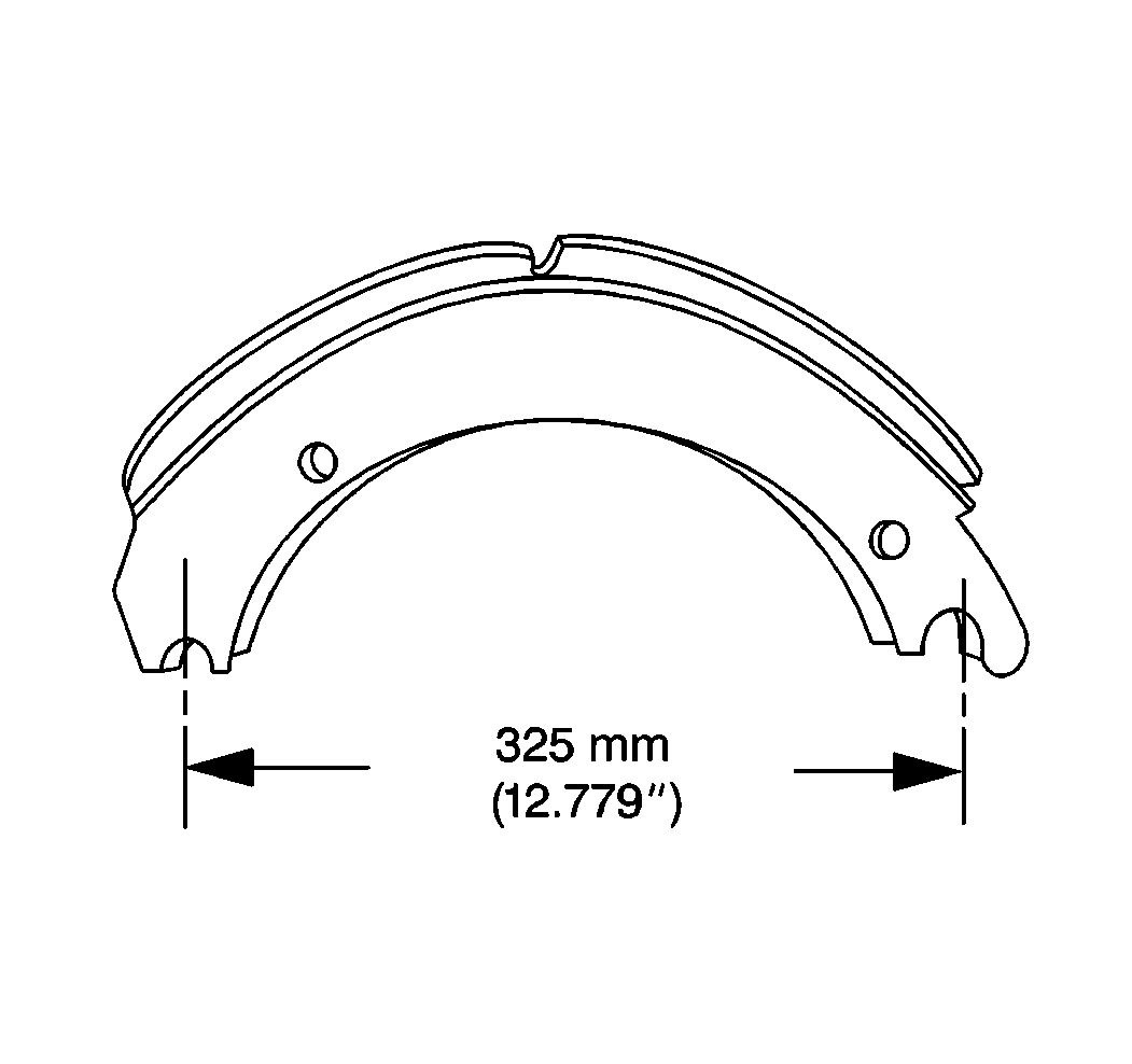
- Measure the brake shoe anchor pin to the brake shoe roller hole span distance on the 419 mm (16.5 in) diameter brake shoes.
- Replace the brake shoe if the distance from the center of the brake shoe anchor pin slot to the center of the brake shoe roller slot is more than 325 mm (12.779 in).
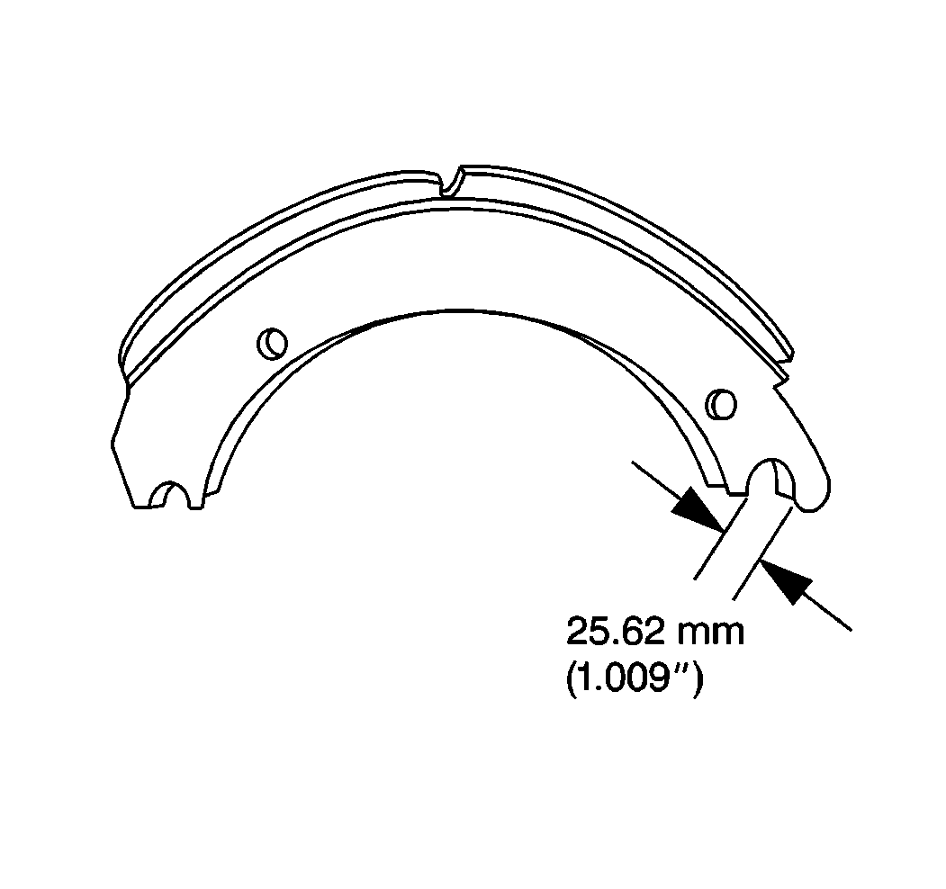
- Measure the brake shoe anchor pin to the brake shoe roller hole span distance on the Rockwell 419 mm (16.5 in) diameter brake shoe.
- Replace the brake shoe if the brake shoe anchor pin hole diameter is more than 25.62 mm (1.009 in).
- Drill out the rivets.
- Disassemble the brake lining (17) from the brake shoe.
- Clean the burrs and the high spots from the brake shoe with a file.
- Clean the brake shoe and the brake lining contact surfaces.
- Assemble the new brake lining onto the brake shoe.
Caution: Avoid taking the following actions when you service wheel brake parts:
• Do not grind brake linings. • Do not sand brake linings. • Do not clean wheel brake parts with a dry brush or with compressed air.
Caution: Avoid taking the following actions when you service wheel brake parts:
• Do not grind brake linings. • Do not sand brake linings. • Do not clean wheel brake parts with a dry brush or with compressed air.
Important:
• The primary brake lining must be installed on the primary brake shoe. The first brake shoe past the cam in the direction of the wheel rotation is the primary brake shoe. The primary and the secondary brake shoes can be in either position, depending
on the location of the cam. If the cam is behind the axle, the top brake shoe is the primary brake shoe and the lower brake shoe is the secondary brake shoe. If the cam is in front of the axle, the lower brake shoe is the primary brake shoe. • Follow the rivet machine manufacturer's instruction. • The brake lining to the brake shoe gap at both ends and both sides must not exceed 0.25 mm (0.010 in). • The brake lining to the brake shoe gap between the webs at both ends must not exceed 0.64 mm (0.025 in).
Installation Procedure
- Apply the lubricant to the anchor pins where the anchor pins touch the brake shoes. Use Chassis Lubricant GM P/N 1052497 or equivalent.
- Apply the lubricant to the brake shoe rollers where the brake shoe rollers touch the brake shoes. Use the Chassis Lubricant GM P/N 1052497 or the equivalent.
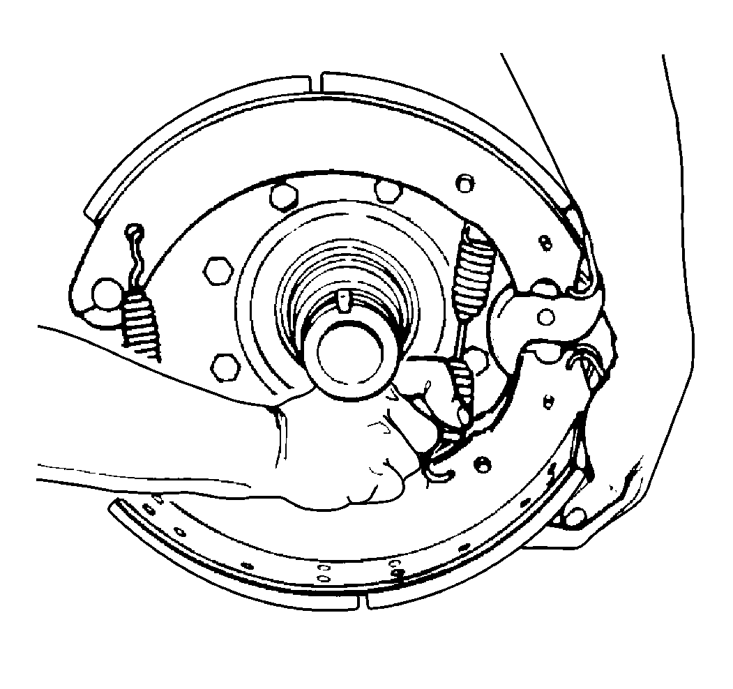
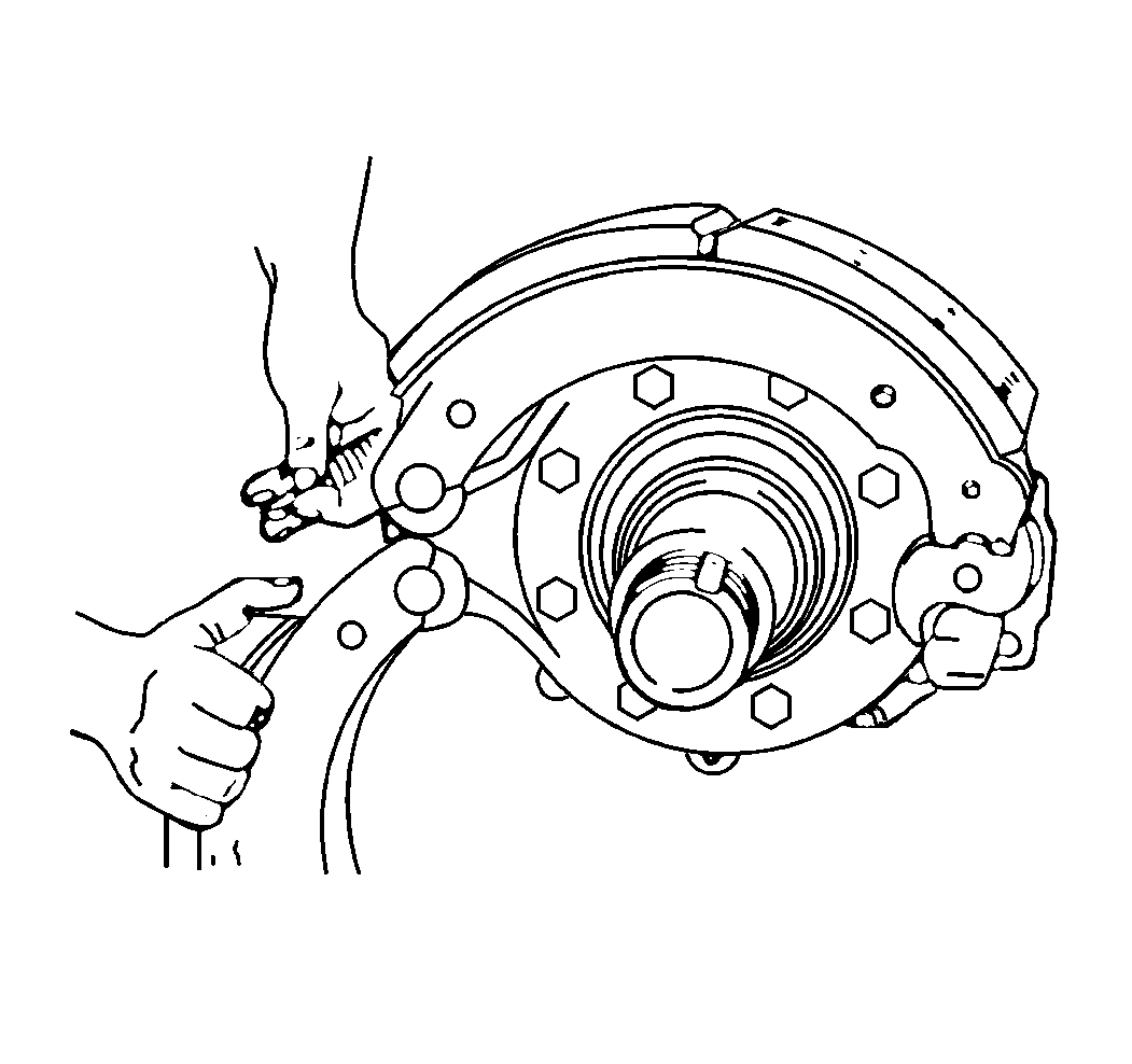
- Put the upper brake shoe in position on the top anchor pin.
- Hold the lower brake shoe on the bottom anchor pin.
- Install the two new brake shoe retaining springs.
- Rotate the lower brake shoe forward.
- Install the new brake shoe return spring.
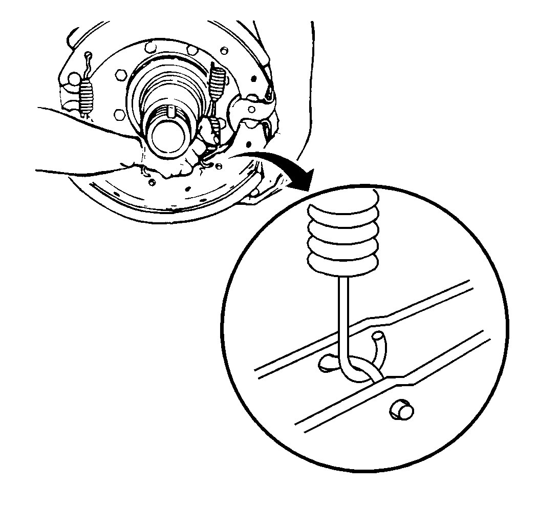
- Install the open end of the return spring hooks toward the camshaft.
- Pull each brake shoe away from the camshaft in order to permit enough space to install the brake shoe rollers and the brake shoe retainers.
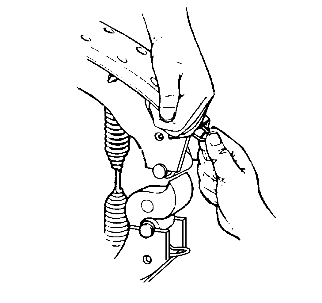
- Press the ears of the brake shoe retainer together in order to permit the brake shoe retainer to fit between the brake shoe webs.
- Push the brake shoe retainer into the brake shoe web until the ears lock in the holes in the brake shoe webs.
- Install the Air Drums. Refer to Brake Drum Replacement .
- Adjust the wheel bearings, if needed. Refer to Wheel Bearing Adjustment .
- Install the tire and the wheel assemblies. Refer to Tire and Wheel Removal and Installation .
- Adjust the brakes. Refer to Air Drum Brake Adjustment .
- Remove the safety stands and lower the vehicle. Refer to Lifting and Jacking the Vehicle .
- Start the engine.
- Charge the air system to the air compressor governor valve cut-out point.
- Stop the engine.
- Uncage the rear air brake chambers. Refer to Caging the Rear Air Brake Chamber .
- Check for the proper brake operation.
- Set the parking brake.
- Remove the wheel blocks.
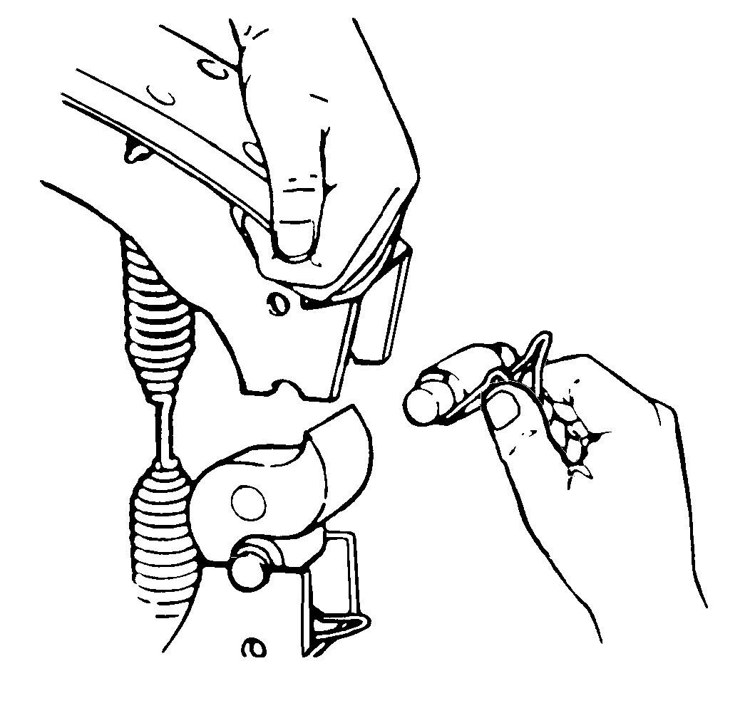
Important: Do not get grease on the part of the brake shoe roller that touches the camshaft.