Service Engine Soon (SES) Light On with Reduction in Engine Power, DTCs P0202 and P2149 or P0207 and P2146 Set (Install Revised 90 Degree Injector Connector with Harness Support Bracket Service Kit)

| Subject: | Service Engine Soon (SES) Light On with Reduction in Engine Power, DTCs P0202 and P2149 or P0207 and P2146 Set (Install Revised 90 Degree Injector Connector with Harness Support Bracket Service Kit) |
| Models: | 2004-2005 Chevrolet Silverado |
| 2004-2005 Chevrolet Kodiak C4500/C5500 Series |
| 2004-2005 GMC Sierra |
| 2004-2005 GMC Topkick C4500/C5500 Series |
| with 6.6L Duramax™ Diesel Engine (VIN 2 - RPO LLY) |
This bulletin is being revised to add additional warranty information. Please discard Corporate Bulletin Number 05-06-04-047A (Section 06 -- Engine/Propulsion System).
Condition
Some customers may comment on the Service Engine Soon light becoming illuminated along with a severe reduction in engine power (limp home mode). Upon investigation, the technician may find DTCs P0202 and P2149 or P0207 and P2146.
Cause
The injector connector circuits on cylinders 2 and 7 are not fully supported near the connector and are more susceptible to terminal breakage from engine vibration.
Correction
If published diagnostics lead to an injector connector, install the revised 90 degree connector and the harness support bracket from the service kit, P/N 98017958, using the following repair procedures.
Repair Procedure for Left Bank Cylinder Number 2
- Disconnect the negative battery cables. Refer to Service Information (SI) for the Battery Negative Cable Disconnect/Connect Procedure (Single Battery) and Battery Negative Cable Disconnect/Connect Procedure (Auxiliary Battery).
- Remove the left wheelhouse panel. Refer to Service Information (SI) for the Wheelhouse Panel Replacement.
- Remove the left charge air cooler inlet pipe. Refer to Service Information (SI) for the Charged Air Cooler Hoses/Pipes Replacement (Left).
- Disconnect cylinder number 2 and cylinder number 4 fuel injector harness connectors.
- Remove the cylinder number 2 glow plug connector nut and remove the cylinder number 2 glow plug harness connector from the glow plug.
- Remove the fuel injector harness bracket bolt.
- Cut the tape to remove the fuel injector harness bracket and discard the bracket.
- Cut cylinder number 2 fuel injector connector off the engine harness approximately 38.1 mm (1.5 in) away from the base of the connector.
- Strip approximately ¼ inch of insulation from both fuel injector circuits and, using the supplied Duraseal® connectors, crimp the new 90 degree fuel injector connector to the engine harness.
- Use an Ultra Torch, or equivalent, to shrink the tubing and set the glue in the Duraseal® connectors.
- Secure the Duraseal® connectors with electrical tape.
- Position the new injector harness bracket to align with the bracket bolt hole and secure to the harness with electrical tape.
- Install the new injector harness bracket and original bolt.
- Install the cylinder number 2 glow plug harness connector and nut.
- Connect the cylinder number 2 and cylinder number 4 fuel injector harness connectors.
- Install the left charge air cooler inlet pipe. Refer to Service Information (SI) for the Charged Air Cooler Hoses/Pipes Replacement (Left).
- Install the left wheelhouse panel. Refer to Service Information (SI) for the Wheelhouse Panel Replacement.
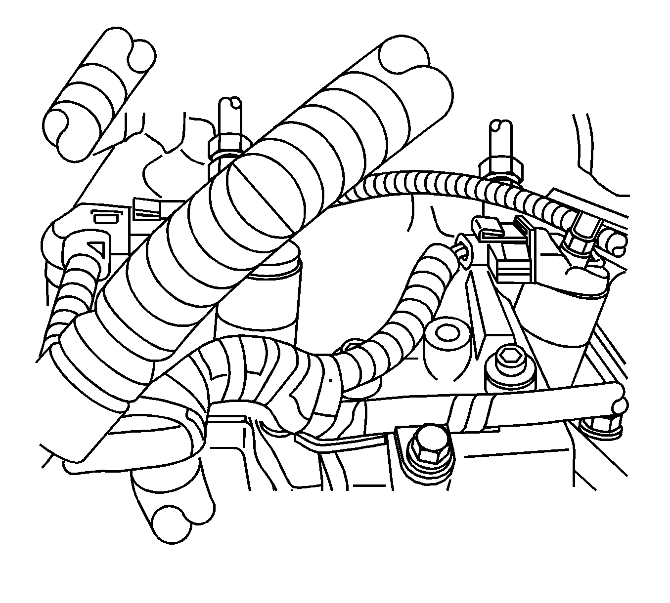
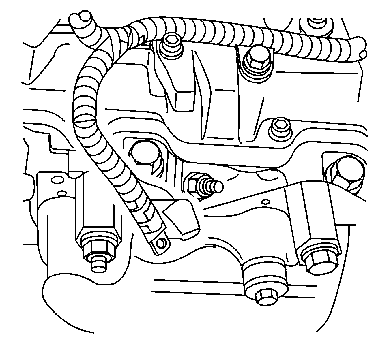
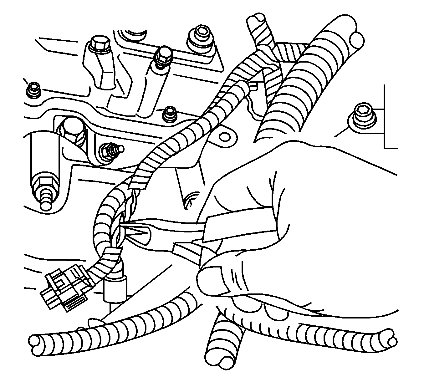
Important: It is not necessary to maintain the same polarization of the injector circuits.
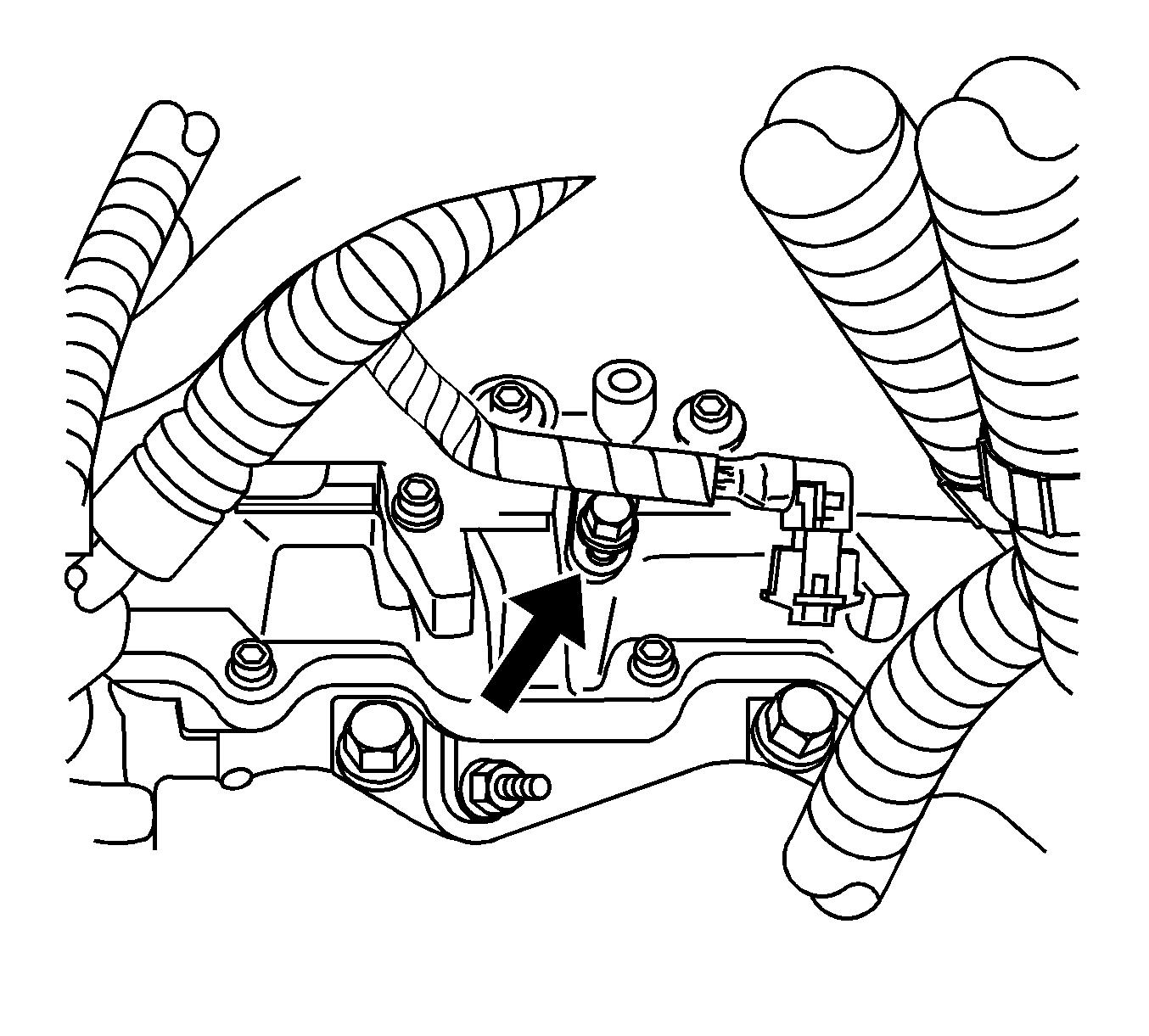
Tighten
Tighten the fuel injector harness bracket bolt to 10 N·m (89 lb in).

Tighten
Tighten the glow plug harness connector nut to 2 N·m (18 lb in).
Repair Procedure for Right Bank Cylinder Number 7
- Remove the fuel filter assembly bolts.
- Position the fuel filter assembly out of the way.
- Disconnect cylinder number 7 fuel injector harness connector and cut the number 7 fuel injector harness connector wires directly at the base of the connector.
- Strip approximately ¼ inch of insulation from both fuel injector circuits and, using the supplied Duraseal® connectors, crimp the new 90 degree fuel injector connector to the engine harness.
- Use an Ultra Torch, or equivalent, to shrink the tubing and set the glue in the Duraseal® connectors.
- Secure the Duraseal® connectors with electrical tape.
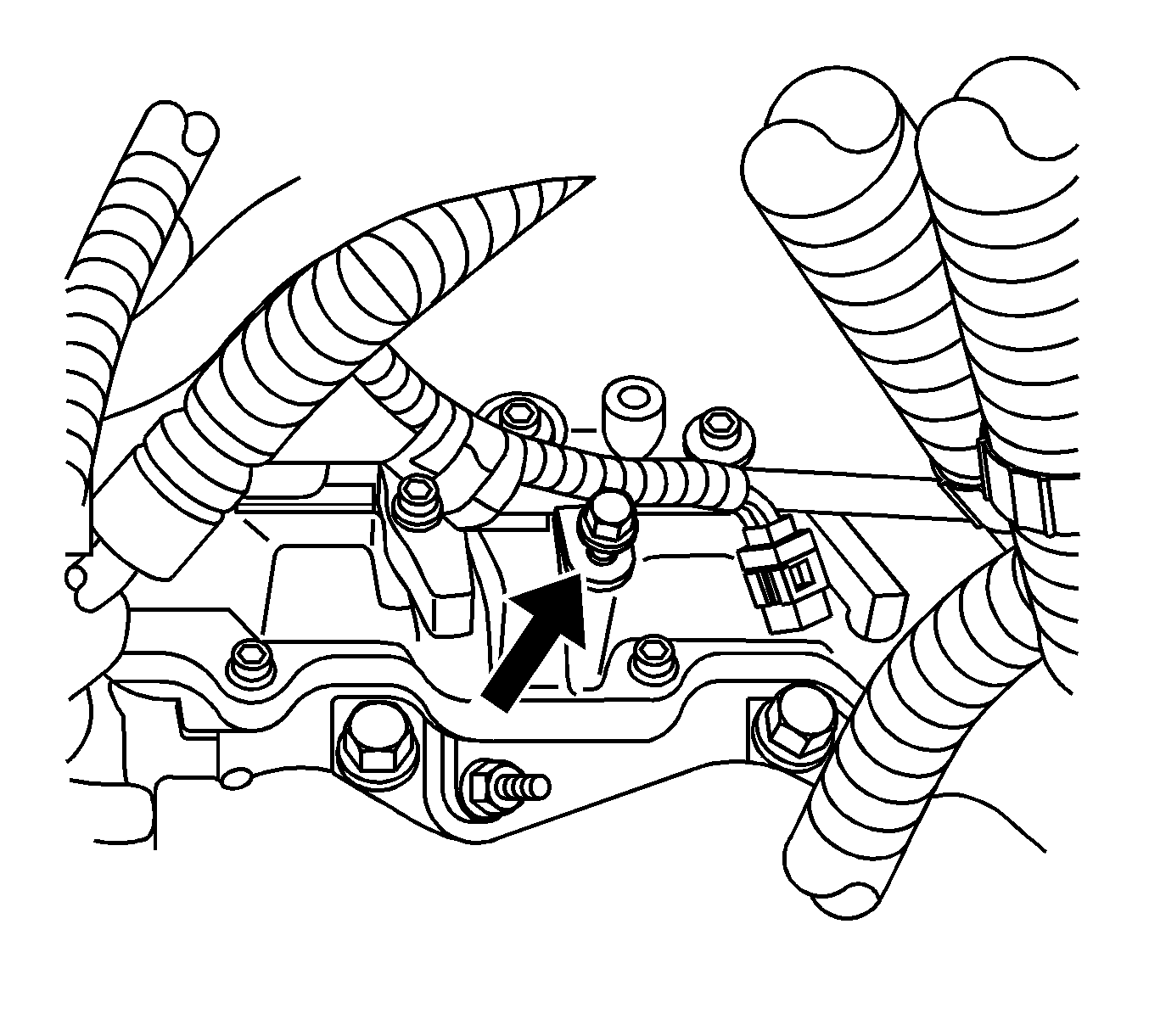
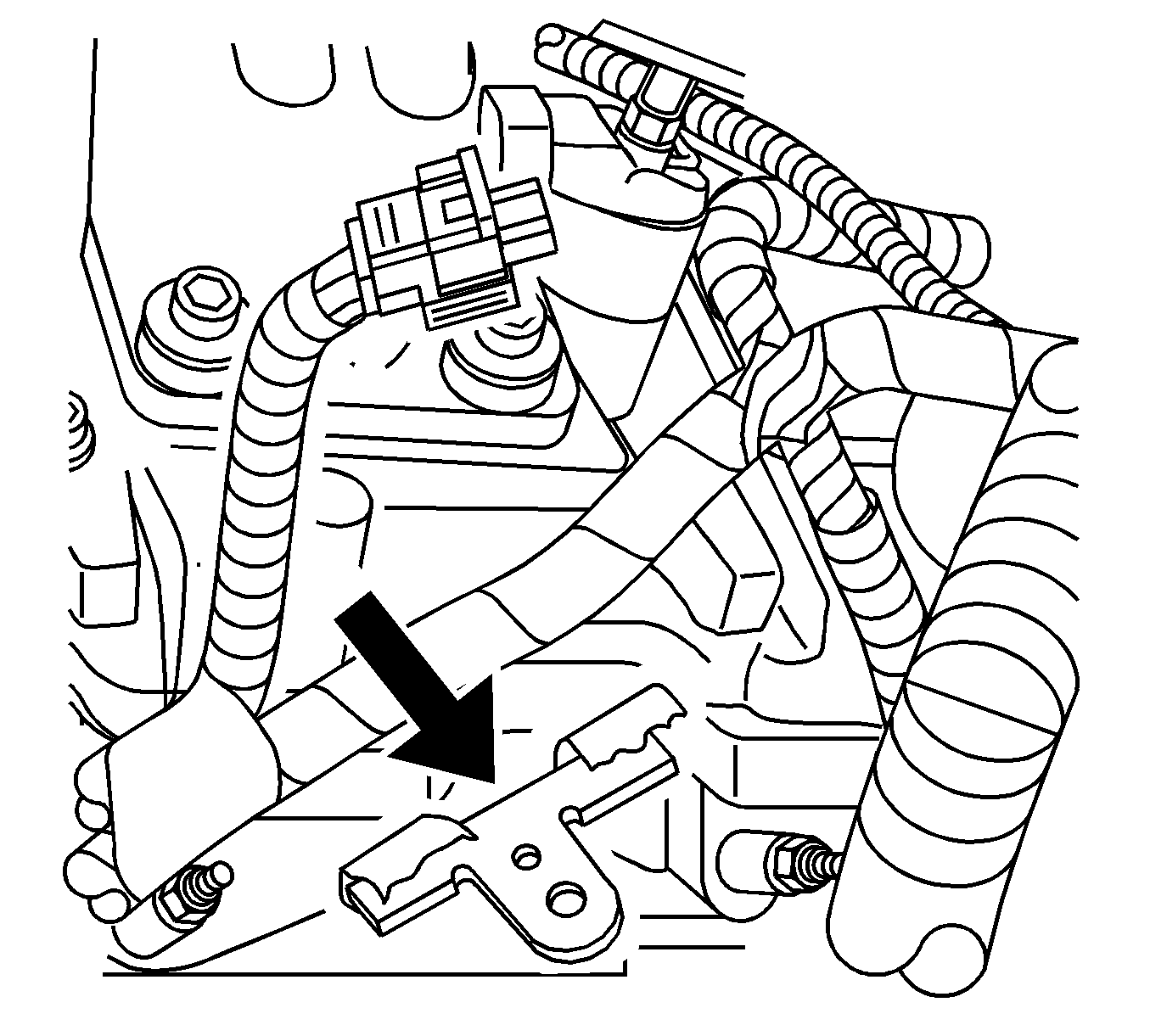
- Install the new injector harness bracket to the upper valve cover.
- Install the injector harness bracket bolts supplied with the kit.
- Connect the cylinder number 7 injector harness connector.
- Install the injector harness to the bracket as shown.
- Install the fuel filter assembly.
- Install the fuel filter assembly bolts.
- Connect the negative battery cables. Refer to Service Information (SI) for the Battery Negative Cable Disconnect/Connect Procedure (Single Battery) and Battery Negative Cable Disconnect/Connect Procedure (Auxiliary Battery).
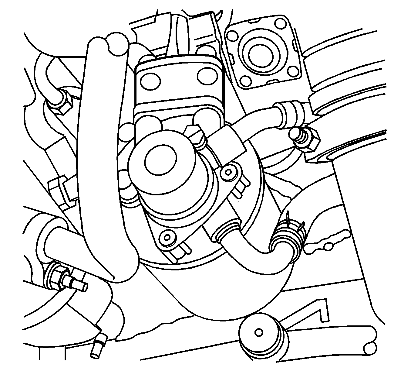
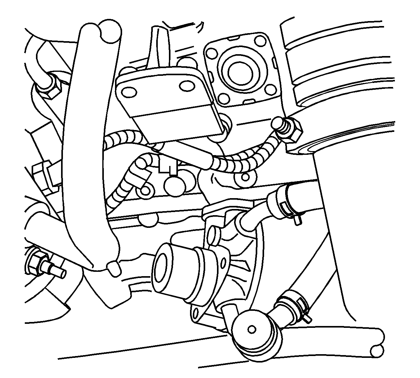
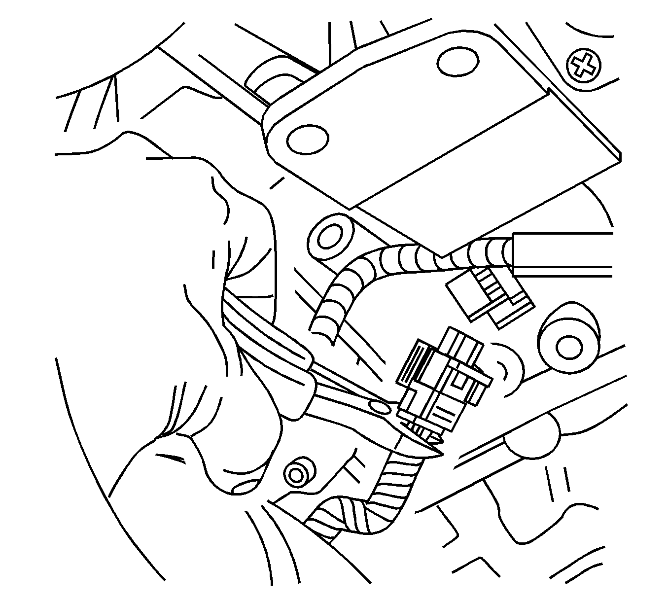
Important: It is not necessary to maintain the same polarization of the injector circuits.
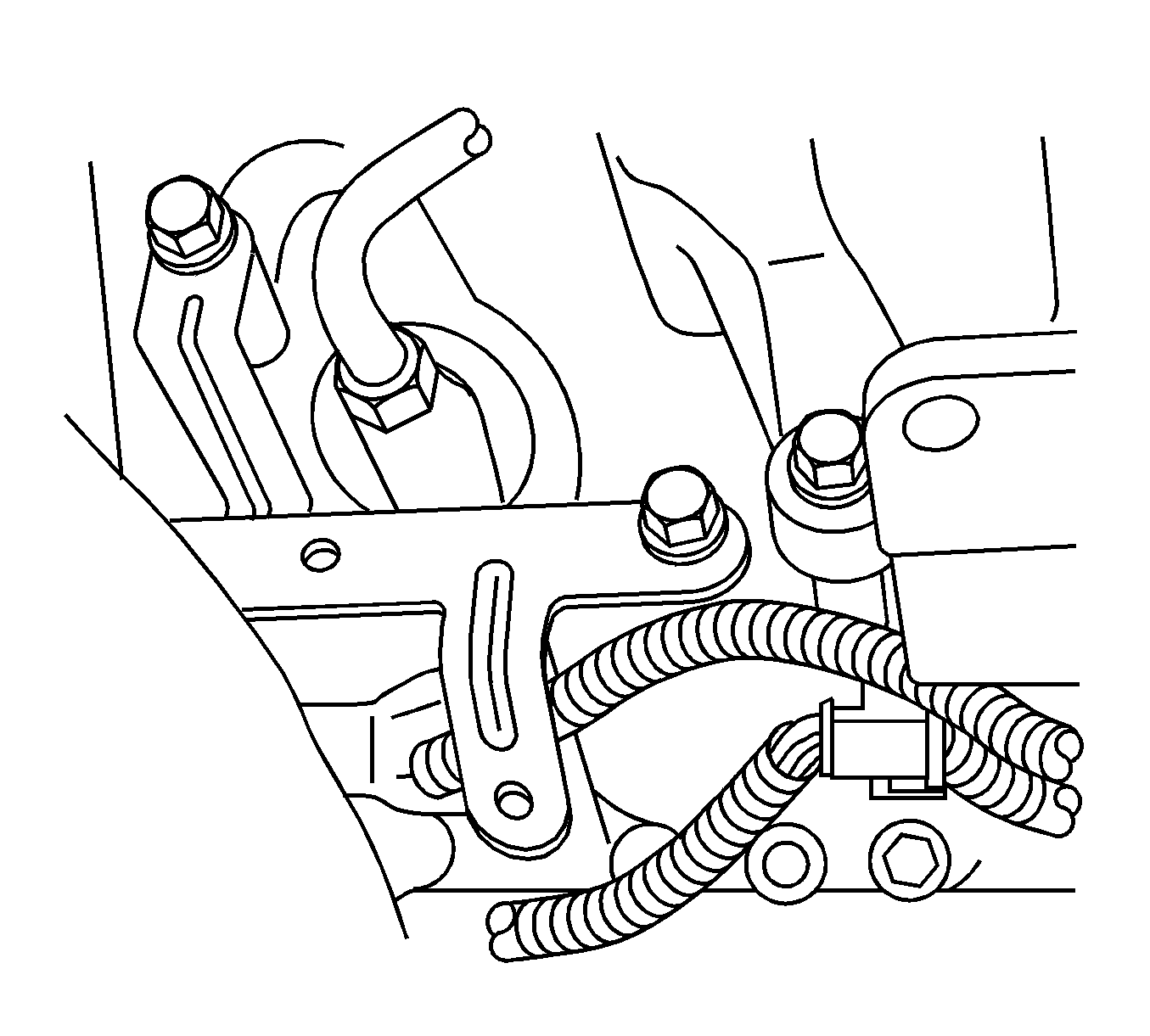
Tighten
Tighten the injector harness bracket bolts to 20 N·m (15 lb ft).
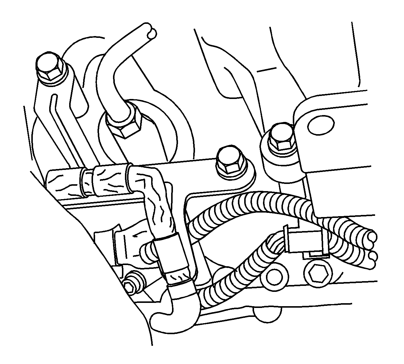
Tighten
Tighten the fuel filter assembly bolts to 20 N·m (15 lb ft).
Parts Information
Part Number | Description | Qty |
|---|---|---|
98017958 | Injector Connectors #2 and #7 Service Repair Kit | 1 |
Warranty Information
For vehicles repaired under warranty, use:
Labor Operation | Description | Labor Time |
|---|---|---|
J7709* | Service Kit, Revised 90 Degree Injector Harness Connectors w/Harness Support Brackets - Install | 0.9 hr |
*This labor operation number is for bulletin use only. This number will not be published in the Labor Time Guide. | ||
Warranty Coverage
| • | 2004 Model - US & Canada - Light and Medium Duty Trucks - 5 Years or 100,000 miles/160,000 kilometers |
| • | 2005 Model - US - Light Duty Trucks - 5 Years or 50,000 miles |
| • | 2005 Model - US - Medium Duty Trucks - 5 Years or 100,000 miles |
| • | 2005 Model - Canada - Light and Medium Duty Trucks - 5 Years or 160,000 kilometers |
