Tools Required
| • | J 44725 Gear Pack
Assembly Fixture |
| • | J 44731 Input
Shaft Seal Installer |
| • | J 44732 Output
Shaft Seal Installer |
| • | J 44745 Countershaft
Bearing Race Installer |
| • | J 44746 Mainshaft/Input
Shaft Bearing Race Installer |
Notice: Various transmission components require heating to 150°C (300°F)
for 30 minutes for proper installation. Overheating may damage
the components. Under-heating the components may cause hard installation,
which may damage the components.
Important:
| • | Certain transmission components require preheating to 150°C (300°F).
In order to preheat the components, use an electric oven. It is recommended
to purchase a roaster/oven style locally. The oven should have a temperature setting
thermostat. |
| • | Lubricate all bearings, shafts, and synchronizers with transmission
fluid GM P/N 12378515 (Canadian P/N 88900701) during
installation. |
- Preheat the following components for 30 minutes to 150°C (300°F)
in an electric oven:
| • | The 6th gear bearing bushing |
| • | The reverse gear bearing bushing |
| • | The reverse gear thrust washer |
| • | The mainshaft rear bearing |
- Turn the mainshaft assembly over 180 degrees so that the input
shaft is on the J 44725
. Hold
the input shaft to the mainshaft while turning over.
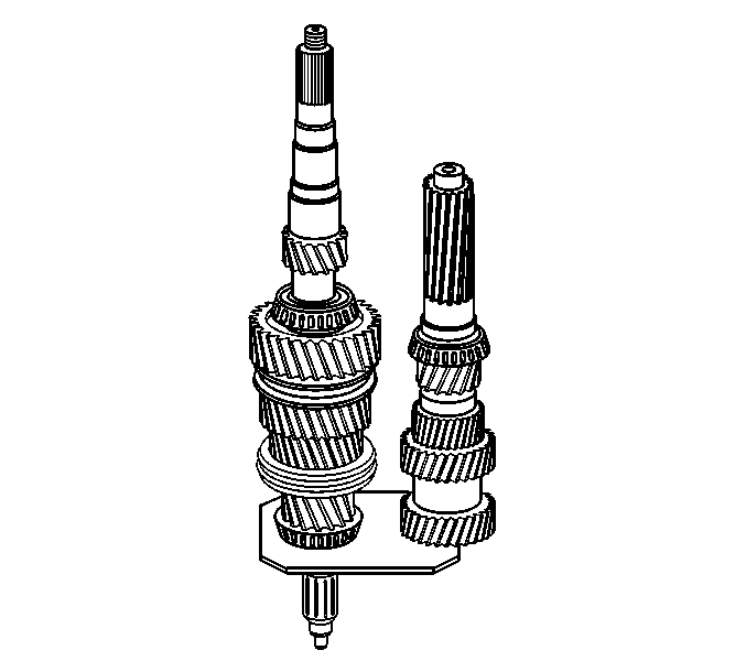
- Position the countershaft on the J 44725
.
Roll the countershaft into place to merger the countershaft
and mainshaft gears.
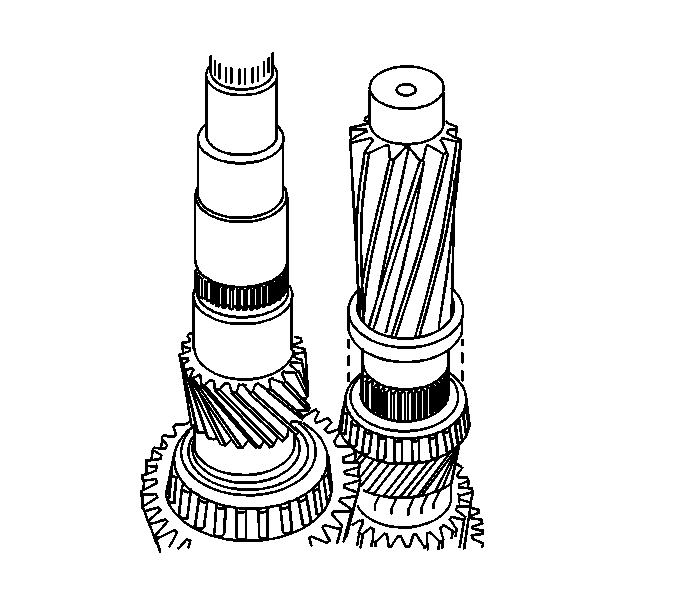
- Install the spacer for the 6th speed
gear synchronizer hub on the countershaft.
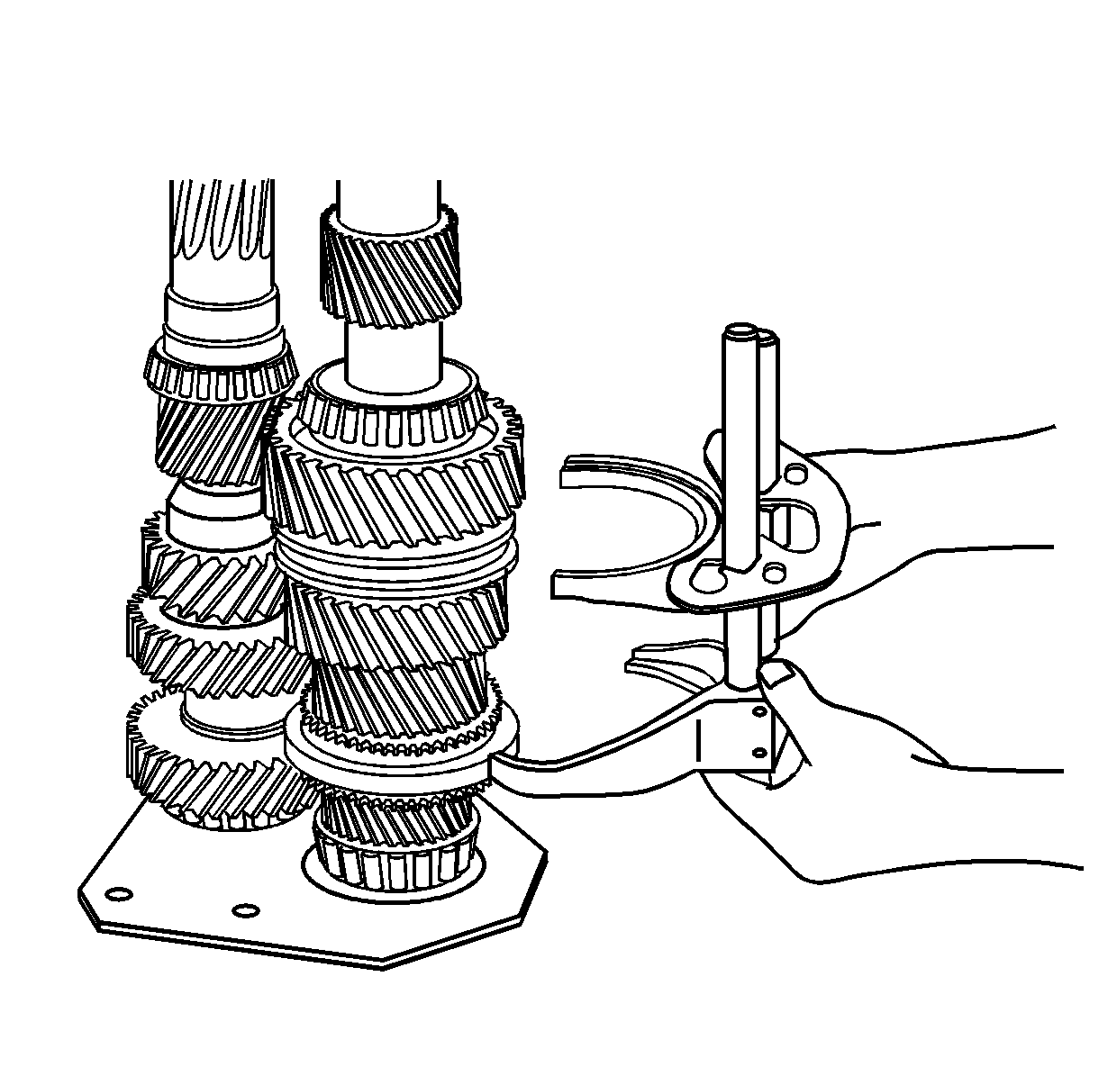
- Assemble the 2nd/3rd shift fork and shift
shaft and the 4th/5th shift fork and shift shaft in the interlock plate.
| • | The part number end of the shift shafts goes up. |
| • | The part number side of the interlock plate goes down. |
- Install the 2nd/3rd shift fork and the 4th/5th shift fork in the synchronizer
sleeves.
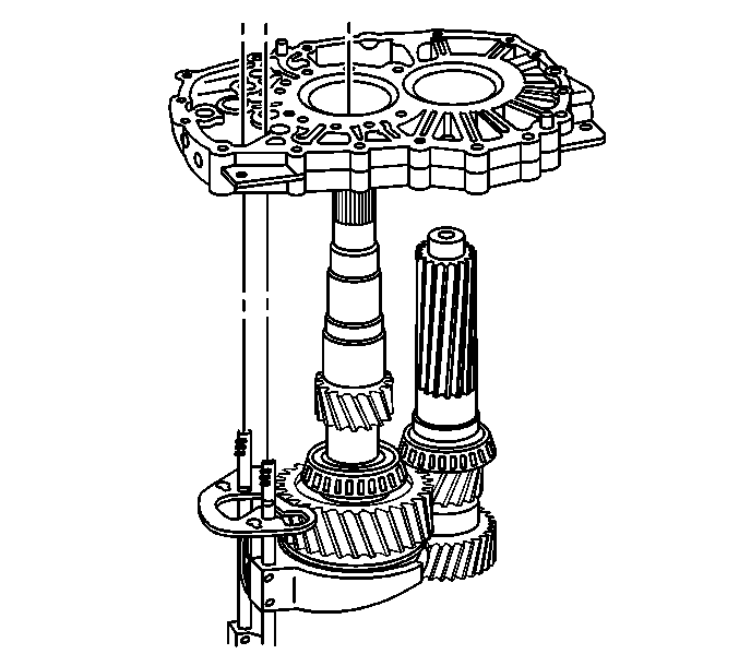
- Install the intermediate case over the
countershaft, the mainshaft, 2nd/3rd shift shaft, and the 4th/5th shift shaft.
| • | Align the shift shafts straight with the shift shaft bearings. |
| • | Wiggle the intermediate case over the shift shafts while installing. |
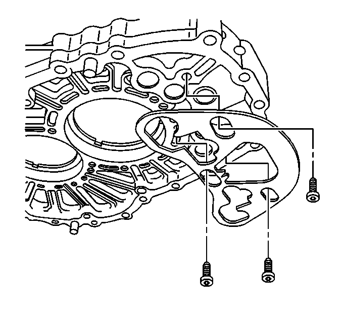
- Install the shift interlock plate to the intermediate case. The part number
side faces away from the intermediate case.
Notice: Use the correct fastener in the correct location. Replacement fasteners
must be the correct part number for that application. Fasteners requiring
replacement or fasteners requiring the use of thread locking compound or sealant
are identified in the service procedure. Do not use paints, lubricants, or
corrosion inhibitors on fasteners or fastener joint surfaces unless specified.
These coatings affect fastener torque and joint clamping force and may damage
the fastener. Use the correct tightening sequence and specifications when
installing fasteners in order to avoid damage to parts and systems.
- Install the interlock plate bolts. Ensure the shoulder of the bolts do not
catch on the plate.
Tighten
Tighten the interlock plate bolts to 10 N·m
(88 lb in).
- Ensure the interlock plate moves freely.
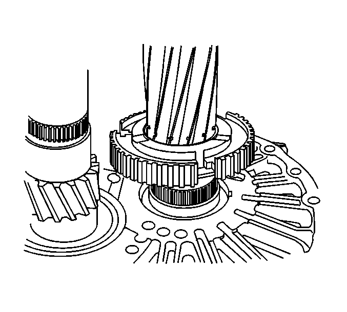
- Install the retaining ring in the 6th
speed gear synchronizer hub, if removed.
- Install the 6th speed gear synchronizer hub on the countershaft.
| • | The hub side with the retaining ring goes toward the intermediate case. |
| • | The hub should slide on the countershaft. |
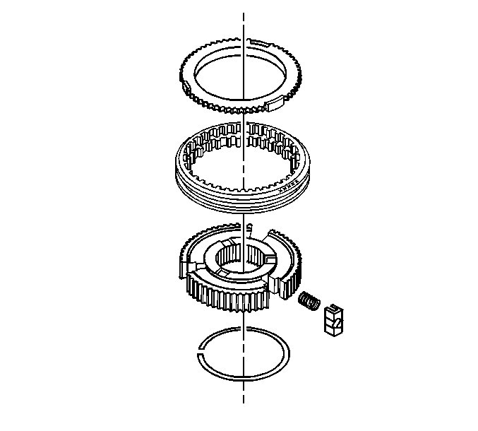
- If not already assembled, assemble the
6th gear synchronizer assembly.
The 6th gear synchronizer springs are
22.7 mm (0.893 in) long.
| 13.1. | Install all three springs and the pressure pieces in the synchronizer
sleeve. |
| 13.2. | Install the 6th gear synchronizer sleeve on the hub. The part numbered
side goes up. |
| | Important: In order to prevent the springs and pressure
pieces from jumping out of position, install the 6th gear synchronizer blocking
ring. Move the sleeve to lock the pressure pieces in position.
|
| 13.3. | Install the 6th gear synchronizer blocking ring. Align the tabs on the blocking
ring with the slots in the hub. |
| 13.4. | Pull up on the sleeve to lock the pressure pieces in the neutral position. |
Caution: Refer to Handling Preheated Parts Caution in the Preface section.
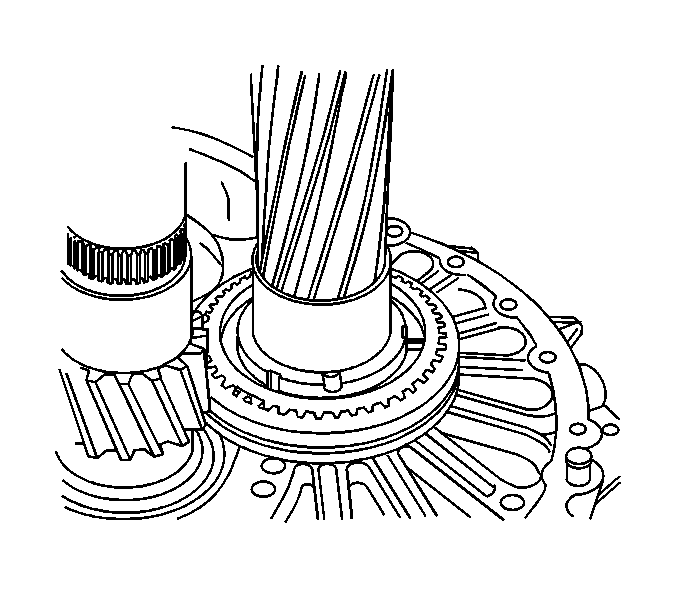
- Wearing protective gloves, install the preheated 6th gear bushing on the
countershaft. Rotate the bushing while installing in order to seat them fully and
squarely.
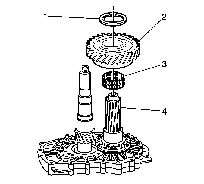
- Install the 6th speed gear bearing (3).
- Install the 6th speed gear (2).
- Install the 6th speed gear spacer washer (1).
- Lightly lubricate the components with GM P/N 12378515
(Canadian P/N 88900701).
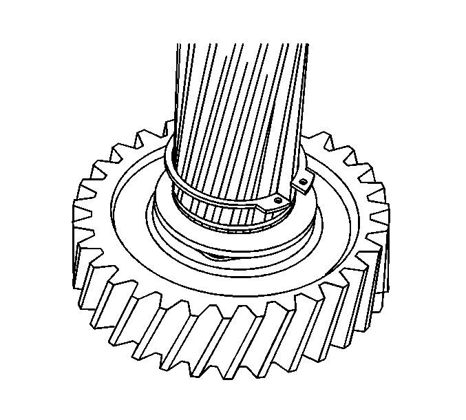
- Install the 6th speed gear retaining ring.
| • | The retaining rings are different thicknesses. |
| • | Select a retaining ring that fills the groove. |
| • | Retaining ring tabs should be under the gear teeth. |
| • | Ensure the retaining ring is fully seated. |
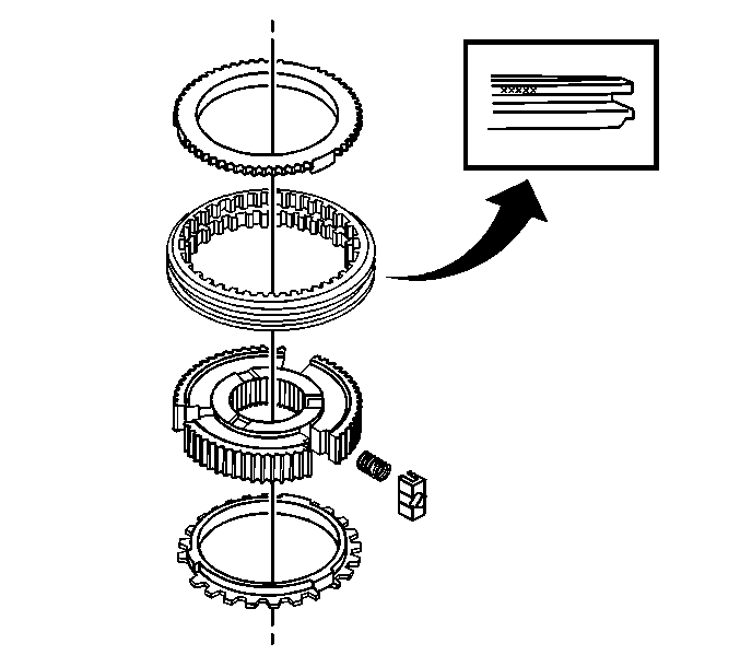
- If the 1st/reverse synchronizer requires
assembly, use the following procedure:
| 20.1. | Lightly lubricate the components with GM P/N 12378515
(Canadian P/N 88900701). |
| 20.2. | With the oil grooves, or the part number side up, install the synchronizer
hub on the 1st gear synchronizer blocking ring. |
| 20.3. | With the synchronizer sleeve chamfer side down, install the sleeve
on the hub. |
| 20.4. | Install the synchronizer springs and pressure pieces. |
| 20.5. | Install the reverse gear synchronizer blocking ring. |
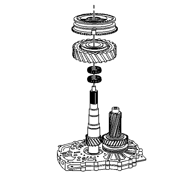
- Install the following components on the
mainshaft:
| 21.1. | Lightly lubricate the bearings with GM P/N 12378515 (Canadian P/N 88900701). |
| 21.2. | The 1st gear bearings |
| 21.4. | The 1st/reverse gear synchronizer assembly with the hub part numbers
facing up |
Caution: Refer to Handling Preheated Parts Caution in the Preface section.
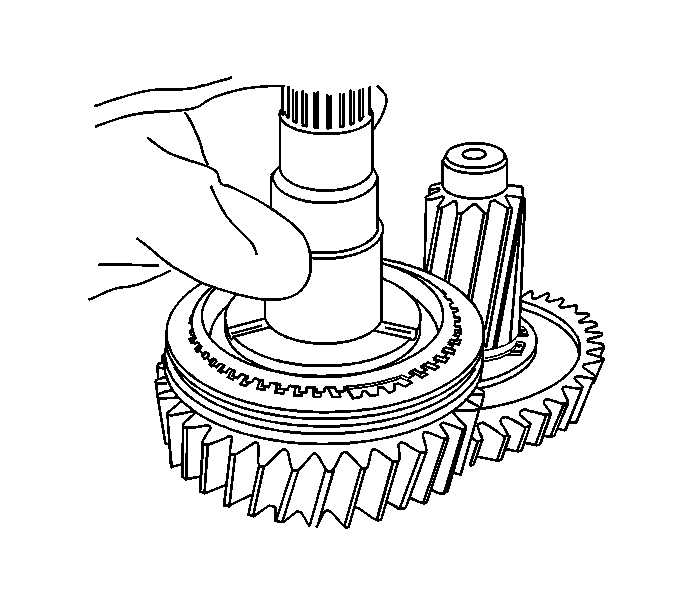
- Wearing protective gloves, install the preheated reverse speed gear bushing
on the mainshaft. Rotate the bushing while installing to ensure the bushing is
fully and squarely seated.
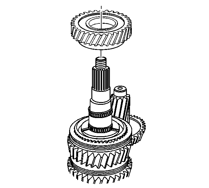
- Install the reverse gear bearings.
- Lightly lubricate the bearings with GM P/N 12378515 (Canadian P/N 88900701).
- Install the reverse gear.
Caution: Refer to Handling Preheated Parts Caution in the Preface section.
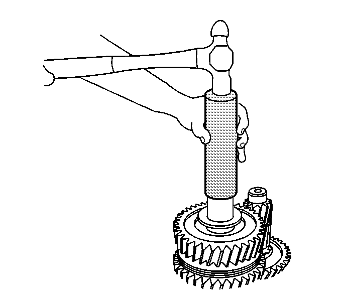
- If RWD, wearing protective gloves, install the preheated thrust washer on
the mainshaft.
- Use the J 44735
and
a hammer to ensure the thrust washer is fully and squarely seated.
Caution: Refer to Handling Preheated Parts Caution in the Preface section.
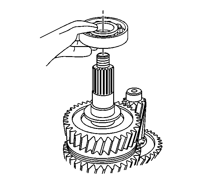
Important: The mainshaft rear bearing for a 4WD vehicle
is a sealed bearing.
- Wearing protective gloves, install the preheated mainshaft rear bearing on
the mainshaft. Rotate the bearing while installing to ensure the bearing is fully
and squarely seated.
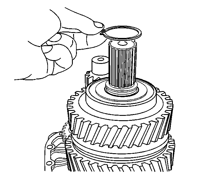
- If 4WD, install the retaining ring for
the mainshaft rear bearing. Ensure the retaining ring is fully seated.
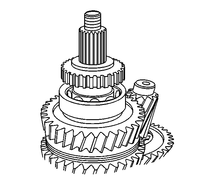
- If RWD, install the vehicle speed sensor
reluctor wheel.
The reluctor wheel should slide on the mainshaft.
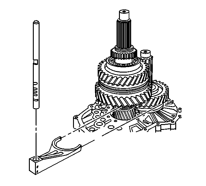
- Install the 6th gear shift fork and rail.
| 31.1. | The part numbered end goes up on the shift rail. |
| 31.2. | Install the shift fork to the 6th gear synchronizer assembly. |
| 31.3. | Move the shift interlock plate toward the 1st/reverse position if necessary. |
| 31.4. | Tap the shift rail with a soft-face hammer into the shift fork
and the intermediate case. |
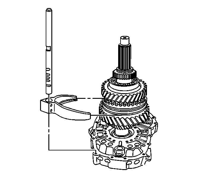
- Install the 1st/reverse shift fork and
rail.
| 32.1. | The part numbered end goes up on the shift rail. |
| 32.2. | Install the shift fork to the 1st/reverse gear synchronizer hub. |
| 32.3. | Move the interlock plate toward 6th gear shift rail. |
| 32.4. | Tap the shift rail with a soft-face hammer into the shift fork
and the intermediate case. |
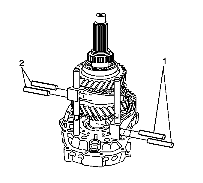
- Install the NEW roll pins in the 6th
gear shift fork (2). A roll pin goes in each hole.
- Install the NEW roll pins in the 1st/reverse gear shift fork (1).
A roll pin goes in each hole.
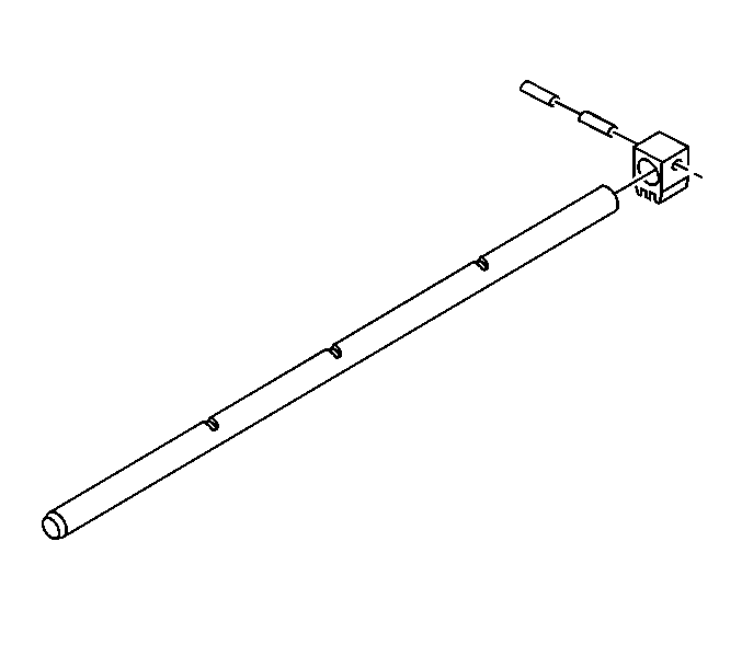
- If removed, install the shift block on
the main shift rail.
| 35.1. | The part numbers on the shift block and the part number on the shift
rail face the same direction. |
| 35.2. | Install the NEW large diameter roll pin. |
| 35.3. | Install the NEW small diameter roll pin with the roll pin split 180 degrees
from the large roll pin split. |
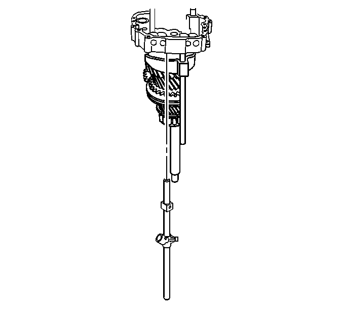
- Install the front internal shift lever
on the main shift rail.
| • | Align the roll pin, or lever end, toward the part numbered end of the
shift rail. |
| • | Do not install the roll pins. |
- With the part numbered end pointing up, install the main shift rail.
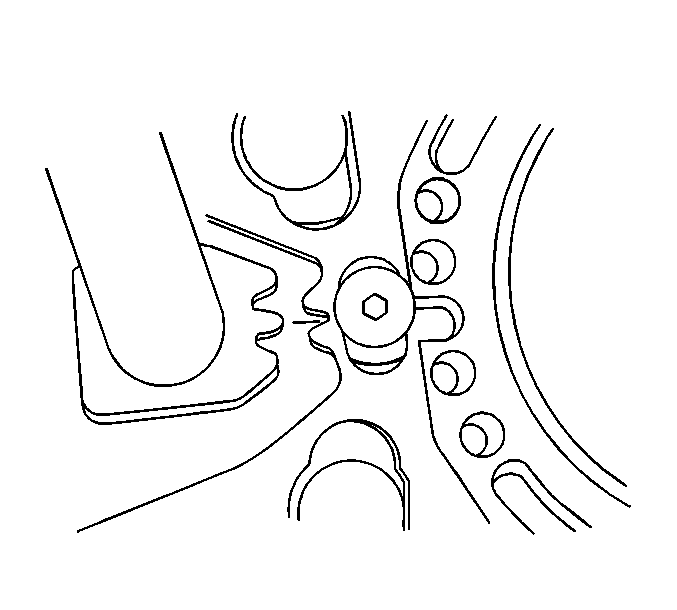
- Align the shift block teeth on the main
shift rail with the shift interlock plate.
The center tooth on the shift
block installs between the two teeth on the shift interlock plate.
- Position the front internal shift lever to align with the notch in
the 2nd/3rd shift rail.
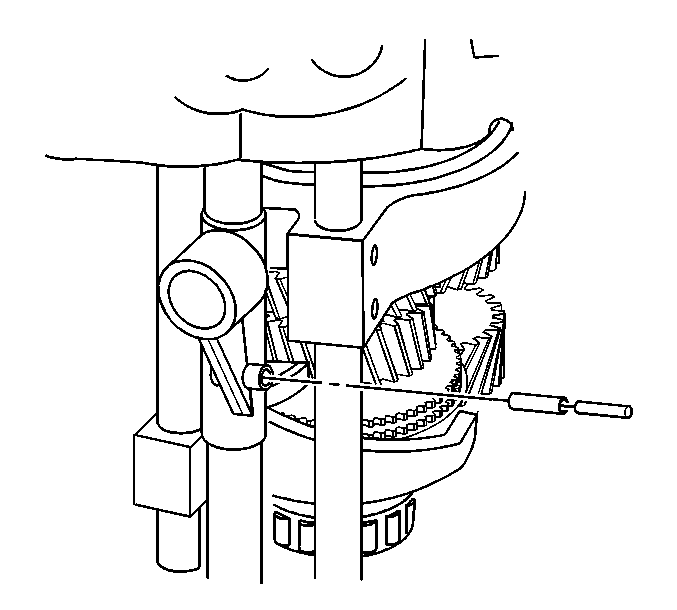
- Install the NEW roll pins in the internal
shift control front lever.
| 40.1. | Install the large diameter roll pin. |
| 40.2. | Align the split on the roll pin away from the transmission. |
| 40.3. | Install the small diameter roll pin inside of the large diameter roll
pin. |
| 40.4. | Align the split on the roll pin toward the transmission. |
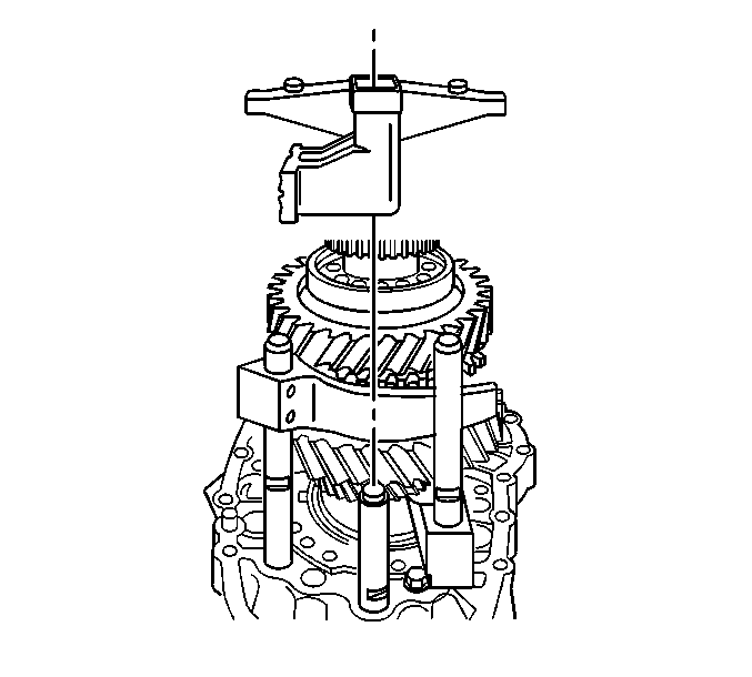
- Install the internal shift control rear
lever on the main shift rail.
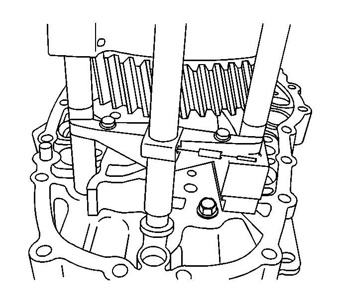
- Align the levers on the internal shift
control rear lever with the slots in the 1st/reverse gear shift rail and the 6th
gear shift rail.
- Install the NEW roll pins in the internal shift control rear lever.
| 43.1. | Install the large diameter roll pin. |
| 43.2. | Align the split on the roll pin away from the transmission. |
| 43.3. | Install the small diameter roll pin inside of the large diameter roll
pin. |
| 43.4. | Align the split on the roll pin toward the transmission. |
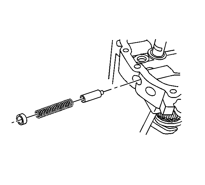
- Install the shift shaft detent plungers
and springs.
- Apply a thin layer of gasket maker GM P/N 12378517 (Canadian P/N 88900757)
to the shift shaft detent caps.
- Using an 11 mm (27/64 in) punch, install the shift
shaft detent caps.
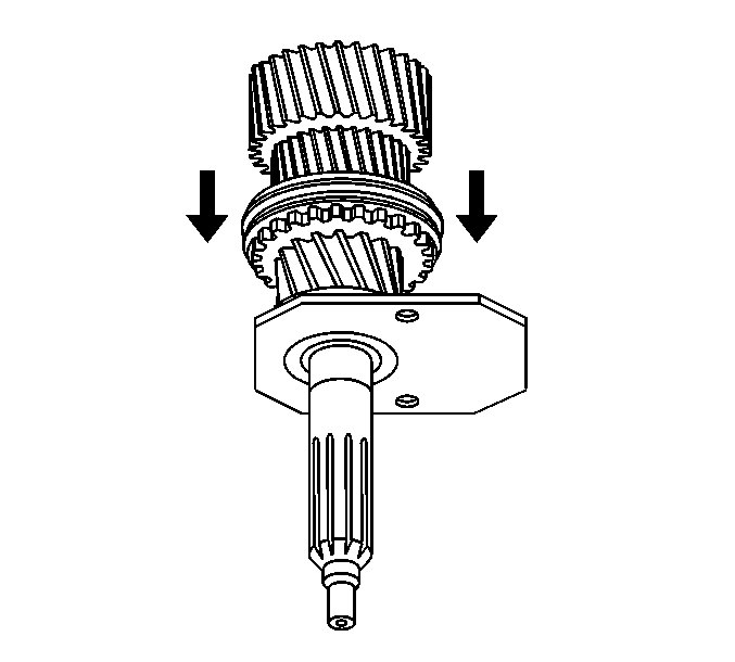
- Shift the transmission into 5th gear in order to lock the input shaft to
the mainshaft.
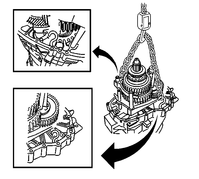
- Install S-hooks and a chain to
the intermediate case.
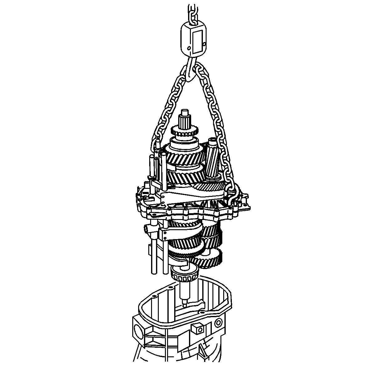
- Position the front of the front case on boards in order to allow the protrusion
of the input shaft.
- Using a suitable lifting device, install the gear assembly to the front
case.
| • | Lower the gear assembly slowly in order to align the intermediate case
dowel pins with the front case. |
| • | Do not use a sealer at this time. |
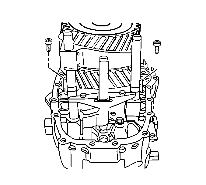
Notice: Use the correct fastener in the correct location. Replacement fasteners
must be the correct part number for that application. Fasteners requiring
replacement or fasteners requiring the use of thread locking compound or sealant
are identified in the service procedure. Do not use paints, lubricants, or
corrosion inhibitors on fasteners or fastener joint surfaces unless specified.
These coatings affect fastener torque and joint clamping force and may damage
the fastener. Use the correct tightening sequence and specifications when
installing fasteners in order to avoid damage to parts and systems.
- Install the two intermediate to front case bolts.
Tighten
Tighten the intermediate case bolts to 23 N·m
(17 lb ft).
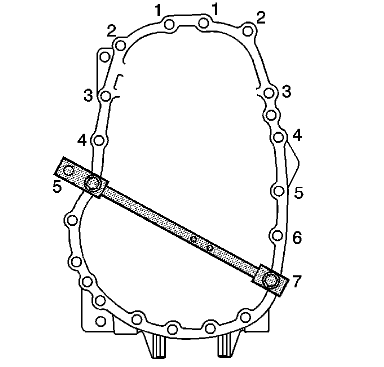
- Assemble the J 44739
to
the intermediate case, to measure the countershaft preload.
| 52.1. | Install the crosspiece so that the 2 holes are closer to the
single bolt hole upright in the lowest notch. Do not tighten the thumbscrew. |
| 52.2. | Install the crosspiece to the 2 bolt hole upright in the lowest
notch. Do not tighten the thumbscrew. |
| 52.3. | Using a case bolt, install the single bolt hole upright to the 7th
case bolt hole from the top, on the right side of the case. |
| 52.4. | Using a case bolt in the hole away from the upright, install the 2 bolt
hole upright to the 5th case bolt hole from the top, on the left side of the case. |
| 52.5. | Tighten the crosspiece thumbscrews. |
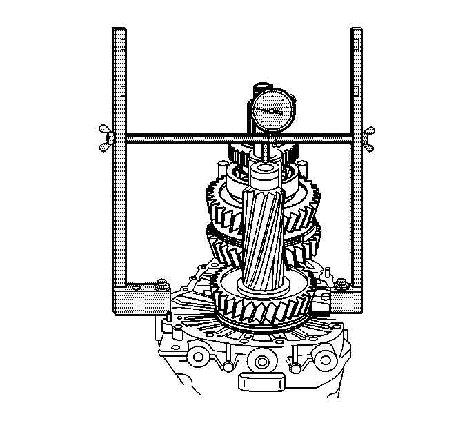
- Use the following procedure in order
to measure the countershaft bearing clearance:
| 53.3. | Using a suitable prying tool, lift up the countershaft. |
| 53.4. | Record the dial indicator reading. This is the countershaft bearing
clearance. |
- Using the following formula, establish the shim thickness required
for the countershaft bearing preload:
| 54.1. | Add the mainshaft preload specification 0.02-0.09 mm (0.0008-0.0035 in)
to the countershaft bearing clearance measurement. |
| 54.2. | The total is the shim thickness required under the countershaft bearing
race in order to set the bearing preload. |
Example
| • | 1.8 mm (0.070 in) mainshaft bearing clearance measurement |
| • | Plus 0.02-0.09 mm (0.0008-0.0035 in) countershaft
preload specification |
| • | Equals 1.82-1.89 mm (0.070-0.074 in) shim thickness
required |
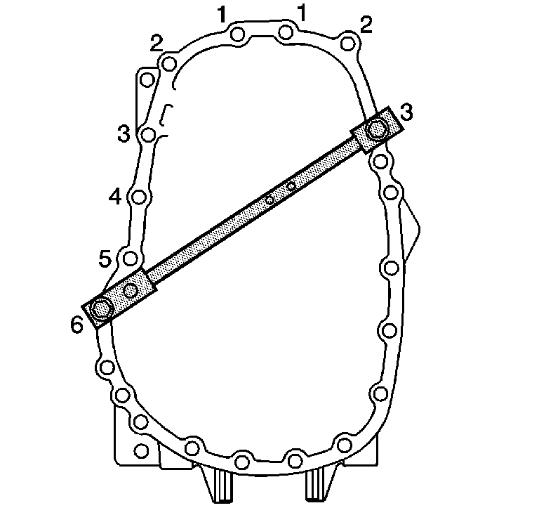
- Assemble
the J 44739
to the intermediate
case, to measure the mainshaft preload.
| 55.1. | Install the crosspiece so that the 2 holes are closer to the
single bolt hole upright in the upper notch, for RWD, or center notch for 4WD.
Do not tighten the thumbscrew. |
| 55.2. | Install the crosspiece to the 2 bolt hole upright in the upper
notch, for RWD, or center notch for 4WD. Do not tighten the thumbscrew. |
| 55.3. | Using a case bolt, install the single bolt hole upright to the 3rd
case bolt hole from the top, on the right side of the case. |
| 55.4. | Using a case bolt in the hole closest to the upright, install the upright
with the 2 bolt holes to the 6th case bolt hole from the top, on the left
side of the case. |
| 55.5. | Tighten the thumbscrews. |
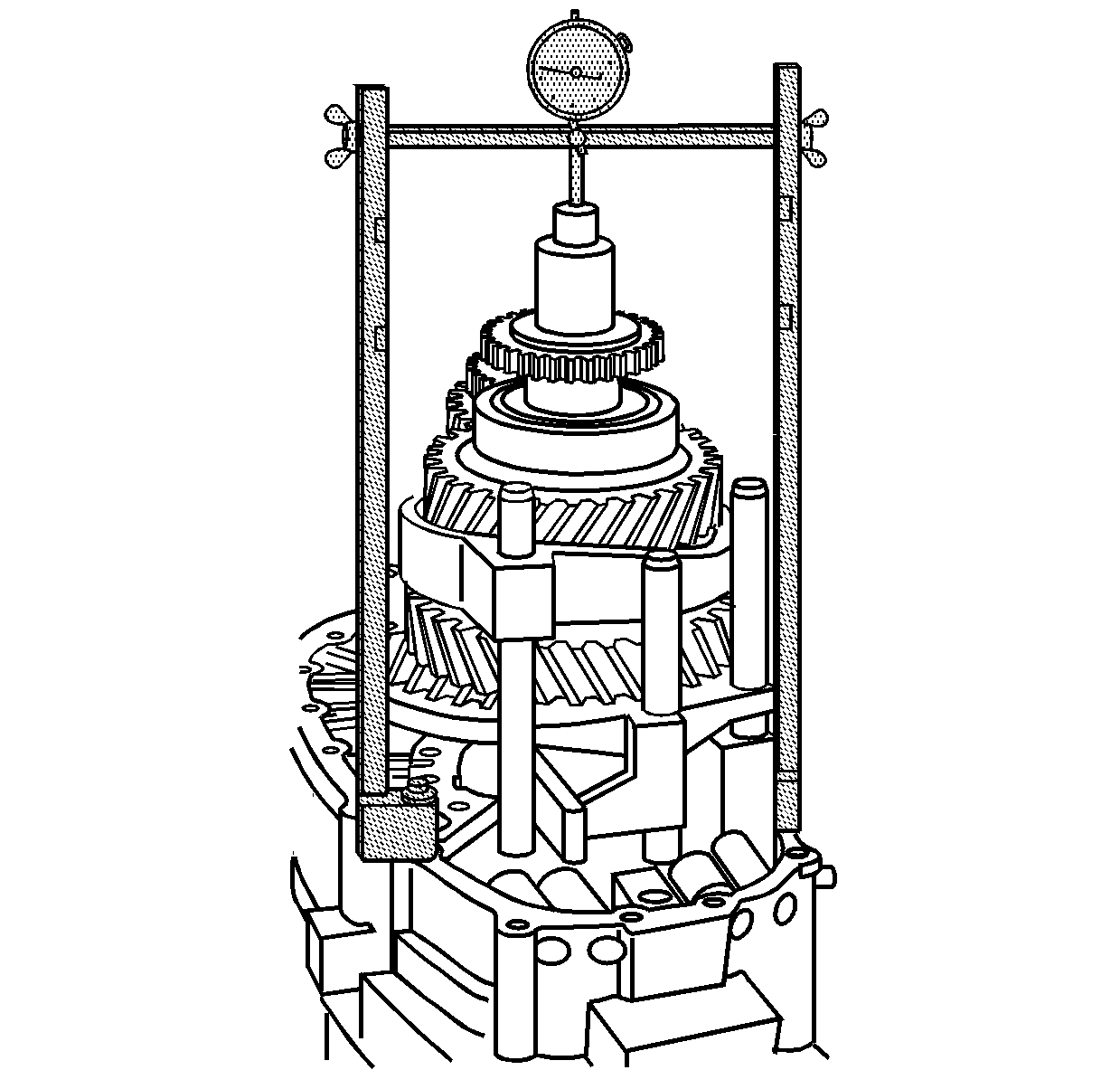
- Use the following procedure in order
to measure the mainshaft bearing clearance.
| 56.3. | Using a suitable prying tool, lift the mainshaft up. |
| 56.4. | Record the dial indicator reading. This is the mainshaft bearing clearance
measurement. |
- Using the following formula, establish the shim thickness required
for the mainshaft bearing preload:
| 57.1. | Measure the input shaft bearing oil deflector thickness. Record this
measurement. |
| 57.2. | Subtract the oil deflector measurement from the mainshaft
bearing clearance measurement. |
| 57.3. | Add the mainshaft preload specification 0.02-0.09 mm (0.0008-0.0035 in). |
| 57.4. | The total is the shim thickness required under the input bearing race
in order to set the bearing preload. |
Example
| • | 0.50 mm (0.020 in) oil deflector thickness |
| • | minus 2.2 mm (0.087 in) mainshaft bearing clearance measurement |
| • | equals 1.7 mm (0.067 in) |
| • | plus 0.02-0.09 mm (0.008-0.0035 in) mainshaft preload
specification |
| • | equals 1.75 mm (0.069 in) shim thickness required |

- Remove the 2 bolts retaining the
intermediate case to the front case.

- Using S-hooks, a chain and a suitable lifting device, remove the gear
assembly.
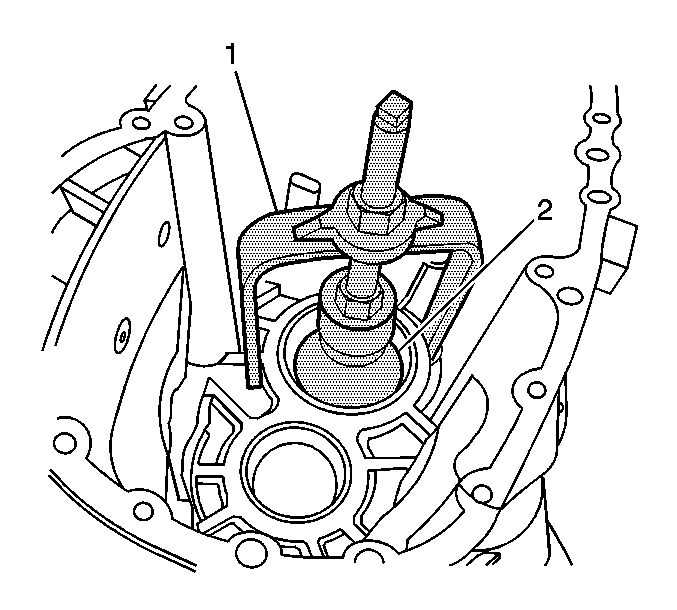
- Remove the mainshaft front bearing race
using the J 44736
(1)
and the J 44733
(2).
| 60.1. | Expand the J 44733
(2)
to fit securely under the bearing race. |
| 60.2. | Align the legs of the J 44733
to rest on the webbing of the case. |
| 60.3. | Remove the mainshaft front bearing race. |
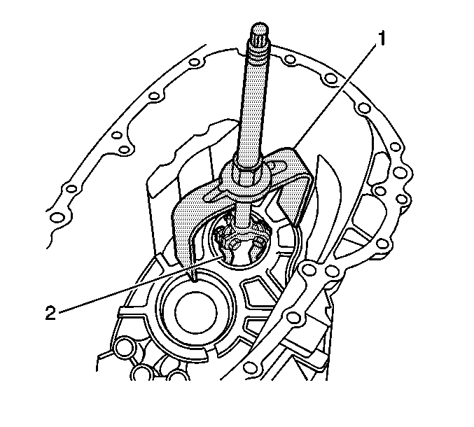
- Remove the countershaft front bearing
race using the J 44736
(1)
and the J 44728
(2).
| 61.1. | Install the J 44728
(2)
in order for the fingers to fit in the notches in the case. |
| 61.2. | Expand the J 44728
(2)
to fit securely in the bearing race. |
| 61.3. | Align the legs of the J 44736
to rest on the webbing of the case. |
| 61.4. | Remove the countershaft front bearing race. |
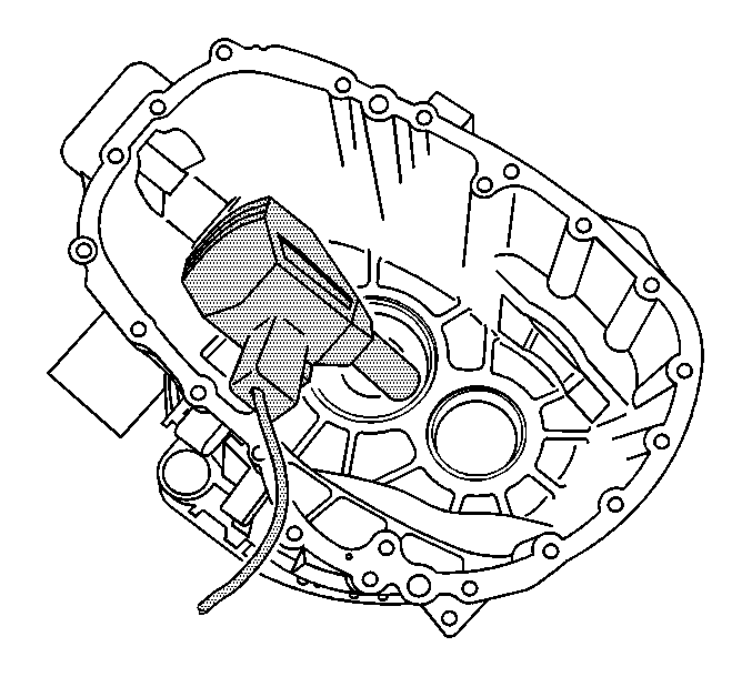
- Using the J 25070
, heat
the front case for 10-15 minutes.
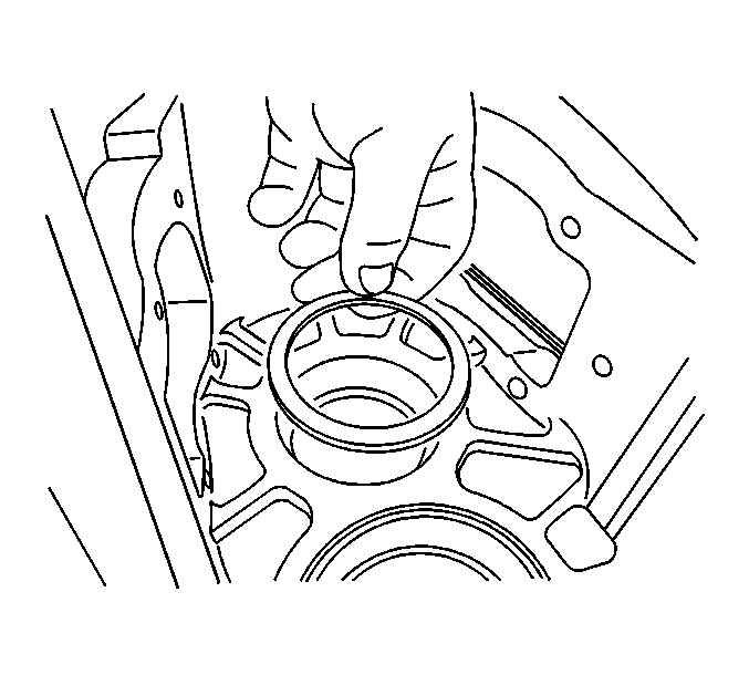
- Install the required shims for the countershaft
bearing preload.
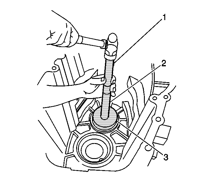
Important: Install the bearing races with the front
case still hot. Do not allow the front case to cool.
- Install the countershaft front bearing race using the J 8092
(1), J 21465-13
(2) and the J 44745
(3).
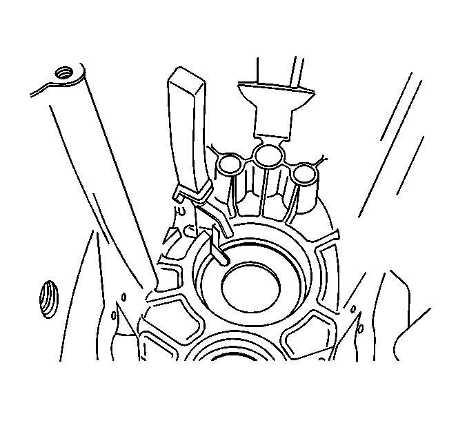
- Install the oil trough.
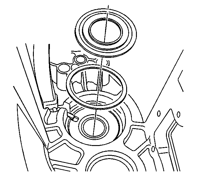
- Install the required shims for the mainshaft
bearing preload.
- Install the input shaft gear oil deflector.
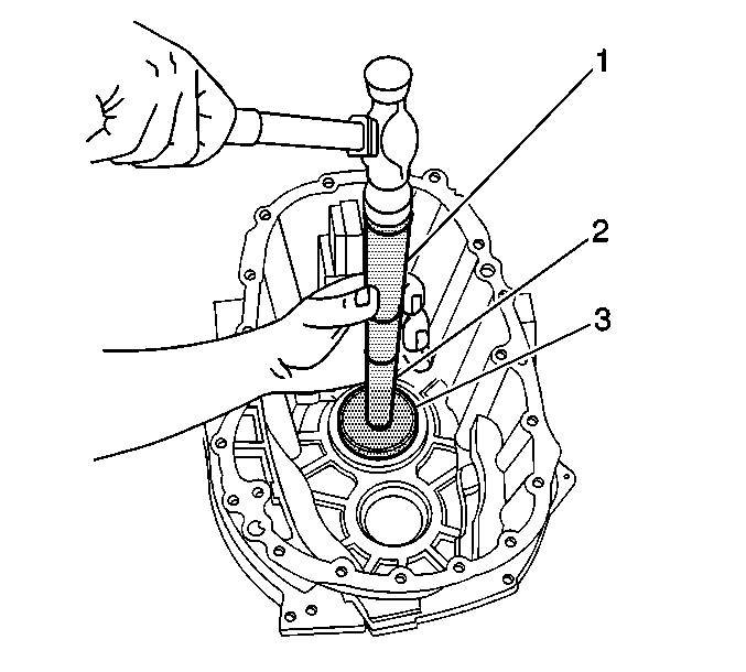
- Install the mainshaft front bearing race
using the J 8092
(1),J 21465-13
(2) and theJ 44746
(3).
- Allow the front case to cool.

- Apply a thin layer of gasket maker GM P/N 12378517 (Canadian P/N 88900757)
to the sealing surface of the front case.
- Using a suitable lifting device, install the gear assembly to the front
case.

- Install the 2 intermediate case to front
case bolts.
Tighten
Tighten the intermediate case bolts to 23 N·m
(17 lb ft).
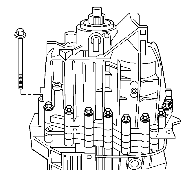
- Apply a thin layer of gasket maker GM P/N 12378517
(Canadian P/N 88900757) to the sealing surface of the rear case.
- Install the rear case on the intermediate case.
- Using a soft-face hammer, tap down on the rear case to seat it
on the dowel pins. Do not use the bolts to draw the case together.
- Install the required brackets and the rear case bolts.
Tighten
Tighten the rear case bolts in a crossover sequence
to 23 N·m (17 lb ft).
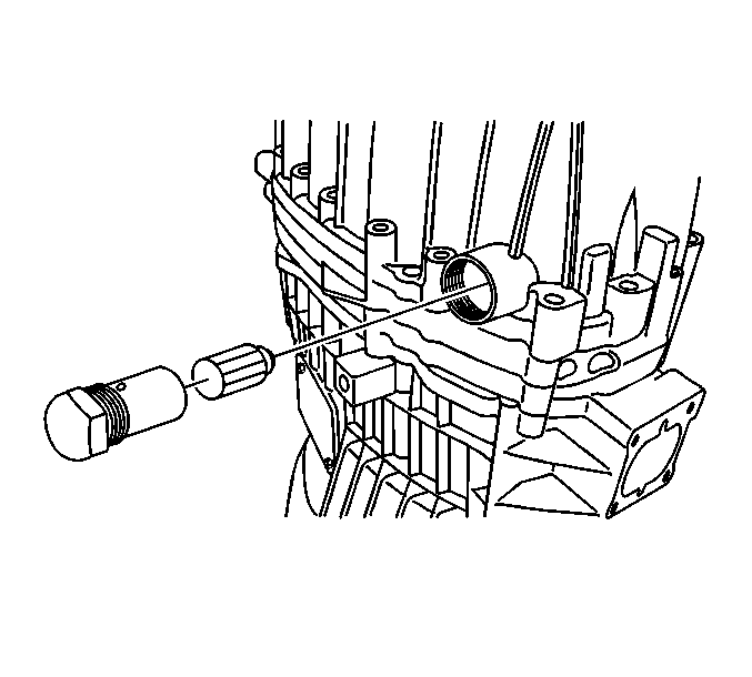
- Apply a thin layer of threadlocker GM P/N 12345382
(Canadian P/N 10953489) to the threads of the shift shaft detent
sleeve.
- Install the shift shaft detent plunger and sleeve.
Tighten
Tighten the detent sleeve to 65 N·m
(48 lb ft).
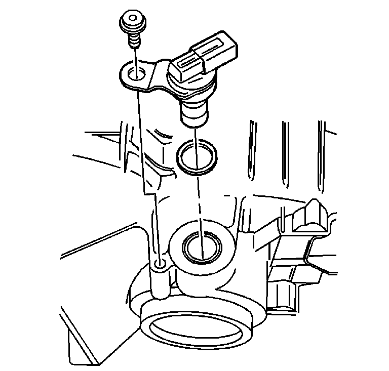
- If
RWD, install the vehicle speed sensor (VSS), with an O-ring seal,
in the rear case.
- Install the VSS bolt.
Tighten
Tighten the VSS bolt to 20 N·m (15 lb ft).
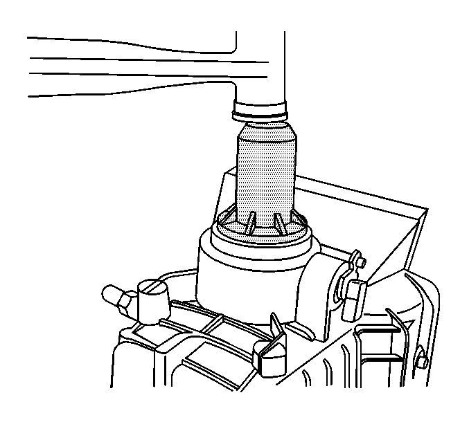
- If RWD, install the rear oil seal using
the J 44732
. The seal installer
will install the seal at the correct depth.
- Lightly lubricate the seal surface with J 36850
or equivalent.
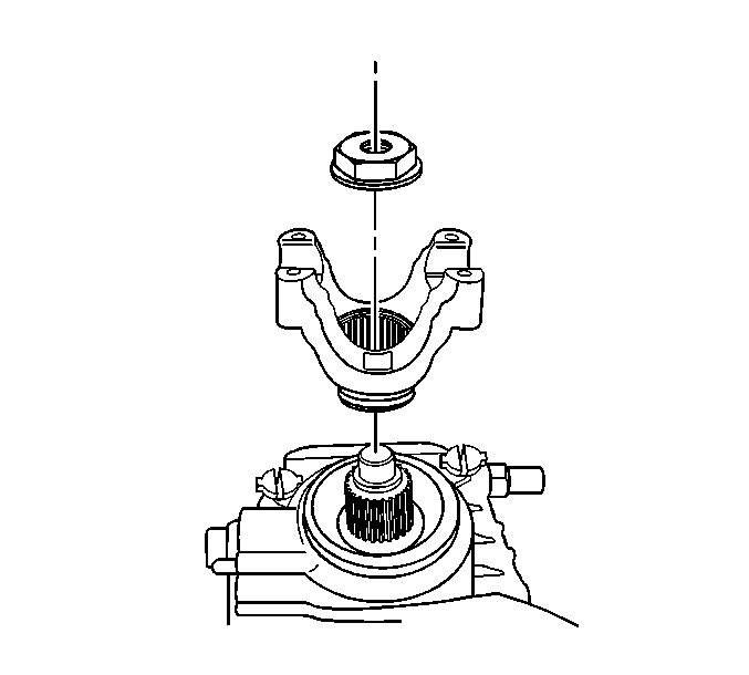
- If RWD, install the propeller shaft yoke.
- Install a NEW propeller shaft yoke nut.
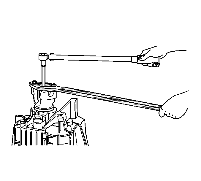
- Install the J 8614-01
in
order to hold the transmission shaft from rotating.
Tighten
Tighten the NEW propeller shaft yoke nut to 330 N·m
(244 lb ft).
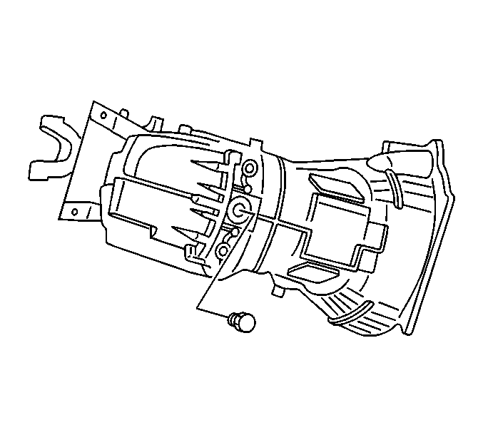
- Install the transmission drain plug and
O-ring seal. Ensure the O-ring seal is not damaged.
Tighten
Tighten the drain plug to 35 N·m (26 lb ft).
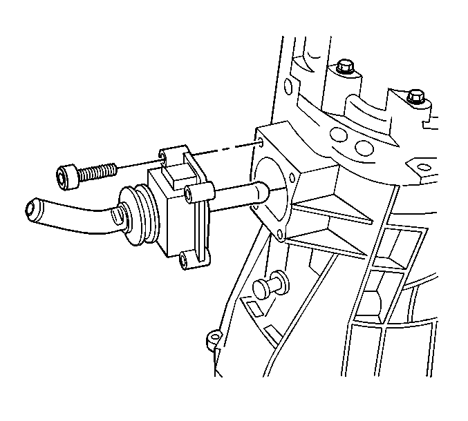
- If the lower shift lever requires installation
before installing in the vehicle, apply a thin layer of gasket maker GM P/N 12378517
(Canadian P/N 88900757) to the sealing surface of the lower shift
control lever.
- Install the lower shift control lever.
- Install the lower shift control lever bolts.
Tighten
Tighten the lower shift control lever bolts to 23 N·m
(17 lb ft).
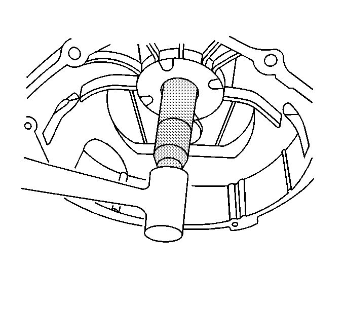
- Position the transmission on the transmission
bottom.
- Install the input shaft seal using the J 44731
.
- Shift the transmission through all of the gears to ensure proper shifting.
- Rotate the transmission by the input shaft.
There should
be resistance to turn.
Tools Required
| • | J 8092 Universal
Driver Handle - 3/4 in - 10 |
| • | J 22828 Input
and Countershaft Race Installer |
| • | J 44725 Gear
Pack Assembly Fixture |
| • | J 44732 Output
Shaft Seal Installer |
| • | J 44745 Countershaft
Bearing Race Installer |
| • | J 44746 Mainshaft/Input
Shaft Bearing Race Installer |
| • | J 45277 Input
Shaft Seal Installer |

Notice: Various transmission components require heating to 150°C (300°F)
for 30 minutes for proper installation. Overheating may damage
the components. Under-heating the components may cause hard installation,
which may damage the components.
Important:
| • | Certain transmission components require preheating to 150°C (300°F).
In order to preheat the components use an electric oven. A roaster/oven
style is recommended. The oven should have a temperature setting thermostat. |
| • | Lubricate all of the bearings, shafts, and synchronizers with transmission
fluid GM P/N 12378515 (Canadian P/N 88900701)
during installation. |
- Preheat the following components to 150°C (300°F), for 30 minutes,
in an electric oven:
| • | The 6th gear bearing bushing |
| • | The reverse gear bearing bushing |
| • | The reverse gear thrust washer |
| • | The mainshaft rear bearing |
- Turn the mainshaft assembly over 180 degrees, so that
the input shaft is on the J 44725
. Hold the input shaft to the mainshaft while turning over.
- Position the countershaft on the J 44725
.
Roll the countershaft into place to merger the
countershaft and mainshaft gears.

- Install the spacer for
the 6th speed gear synchronizer hub on the countershaft.

- Assemble the 2nd/3rd shift
fork and shift shaft and the 4th/5th shift fork and shift shaft
in the interlock plate.
| • | The part number end of the shift shafts go up. |
| • | The part number side of the interlock plate goes down. |
- Install the 2nd/3rd shift fork and the 4th/5th shift
fork in the synchronizer sleeves.

- Install the intermediate
case over the countershaft, the mainshaft, 2nd/3rd shift shaft,
and the 4th/5th shift shaft.
| • | Align the shift shafts straight with the shift shaft bearings. |
| • | Wiggle the intermediate case over the shift shafts while installing. |

- Install the shift interlock
plate to the intermediate case. The part number side faces away from the
intermediate case.
Notice: Use the correct fastener in the correct location. Replacement fasteners
must be the correct part number for that application. Fasteners requiring
replacement or fasteners requiring the use of thread locking compound or sealant
are identified in the service procedure. Do not use paints, lubricants, or
corrosion inhibitors on fasteners or fastener joint surfaces unless specified.
These coatings affect fastener torque and joint clamping force and may damage
the fastener. Use the correct tightening sequence and specifications when
installing fasteners in order to avoid damage to parts and systems.
- Install the interlock plate bolts. Ensure the shoulder of the bolts
do not catch on the plate.
Tighten
Tighten the interlock plate bolts to 10 N·m (88 lb in).
- Ensure the interlock plate moves freely.

- Install the retaining
ring in the 6th speed gear synchronizer hub, if removed.
- Install the 6th speed gear synchronizer hub on the countershaft.
| • | The hub side with the retaining ring goes toward the intermediate
case. |
| • | The hub should slide on the countershaft. |

- If not already assembled,
assemble the 6th gear synchronizer assembly.
The 6th gear
synchronizer springs are 22.7 mm (0.893 in) long.
| 13.1. | Install all 3 springs and the pressure pieces in the synchronizer
sleeve. |
| 13.2. | Install the 6th gear synchronizer sleeve on the hub. The
part numbered side goes up. |
| | Important: In order to prevent the springs and pressure pieces from coming out
of position, install the 6th gear synchronizer blocking ring. Then
move the sleeve to lock the pressure pieces in position.
|
| 13.3. | Install the 6th gear synchronizer blocking ring. Align the tabs
on the blocking ring with the slots in the hub. |
| 13.4. | Pull up on the sleeve to lock the pressure pieces in the neutral
position. |
Caution: Refer to Handling Preheated Parts Caution in the Preface section.

- Wear protective gloves to install the preheated 6th gear
bushing on the countershaft. In order to fully and squarely seat the
bushing, rotate the bushing while installing it.

- Install the 6th speed
gear bearing (3).
- Install the 6th speed gear (2).
- Install the 6th speed gear spacer washer (1).
- Lightly lubricate the components with GM P/N 12378515
(Canadian P/N 88900701).

- Install the retaining
ring for the 6th speed gear.
| • | The retaining rings are different thicknesses. |
| • | Select a retaining ring that fills the groove. |
| • | Retaining ring tabs should be under the gear teeth. |
| • | Ensure the retaining ring is fully seated. |

- If the 1st/reverse synchronizer
requires assembly, use the following procedure:
| 20.1. | Lightly lubricate the components with GM P/N 12378515
(Canadian P/N 88900701). |
| 20.2. | With the oil grooves or the part number side up, install the synchronizer
hub on the 1st gear synchronizer blocking ring. |
| 20.3. | With the synchronizer sleeve chamfer side down, install the sleeve
on the hub. |
| 20.4. | Install the synchronizer springs and pressure pieces. |
| 20.5. | Install the reverse gear synchronizer blocking ring. |

- Install the following
components on the mainshaft:
| 21.1. | Lightly lubricate the bearings with GM P/N 12378515
(Canadian P/N 88900701). |
| 21.2. | The 1st gear bearings |
| 21.4. | The 1st/reverse gear synchronizer assembly with the hub part numbers
facing up |
Caution: Refer to Handling Preheated Parts Caution in the Preface section.

- Wear protective gloves to install the preheated reverse
speed gear bushing on to the mainshaft. Rotate the bushing while installing
it to ensure the bushing is fully and squarely seated.

- Install the reverse gear
bearings.
- Lightly lubricate the bearings with GM P/N 12378515
(Canadian P/N 88900701).
- Install the reverse gear.
Caution: Refer to Handling Preheated Parts Caution in the Preface section.

- If RWD, wear protective gloves to install the preheated
thrust washer on to the mainshaft.
- Use the J 44735
and a hammer to ensure the thrust washer is fully and squarely seated.
Caution: Refer to Handling Preheated Parts Caution in the Preface section.

- Wear protective gloves to install the preheated mainshaft
rear bearing on to the mainshaft. Rotate the bearing while installing
it, to ensure the bearing is fully and squarely seated.
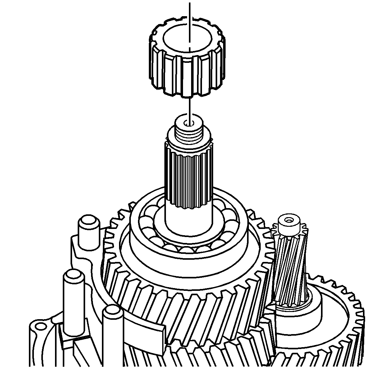
- Install the vehicle speed
sensor reluctor wheel.
The reluctor wheel should slide on the
mainshaft.
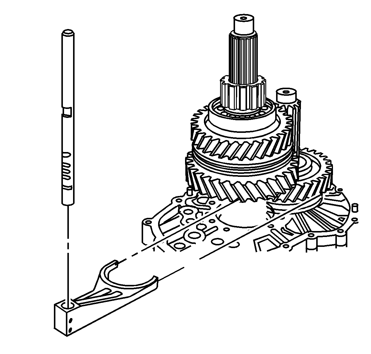
- Install the 6th gear
shift fork and rail.
| 30.1. | The part numbered end goes up on the shift rail. |
| 30.2. | Install the shift fork to the 6th gear synchronizer assembly. |
| 30.3. | Move the shift interlock plate toward the 1st/reverse position,
if necessary. |
| 30.4. | Using a soft-face hammer, tap the shift rail into the shift
fork and the intermediate case. |
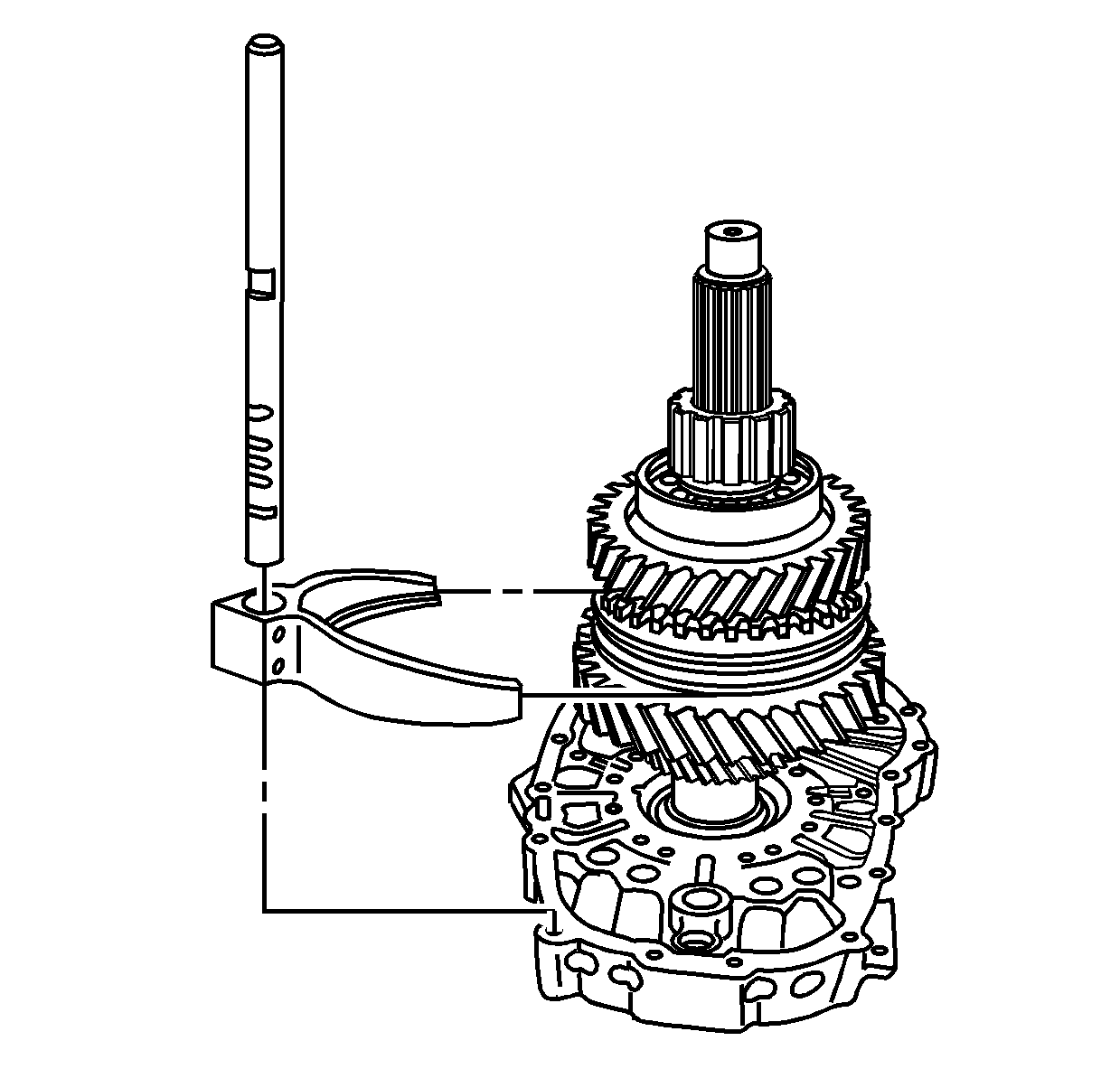
- Install the 1st/reverse
shift fork and rail.
| 31.1. | The part numbered end goes up on the shift rail. |
| 31.2. | Install the shift fork to the 1st/reverse gear synchronizer hub. |
| 31.3. | Move the interlock plate towards 6th gear shift rail. |
| 31.4. | Using a soft-face hammer, tap the shift rail into the shift
fork and the intermediate case. |
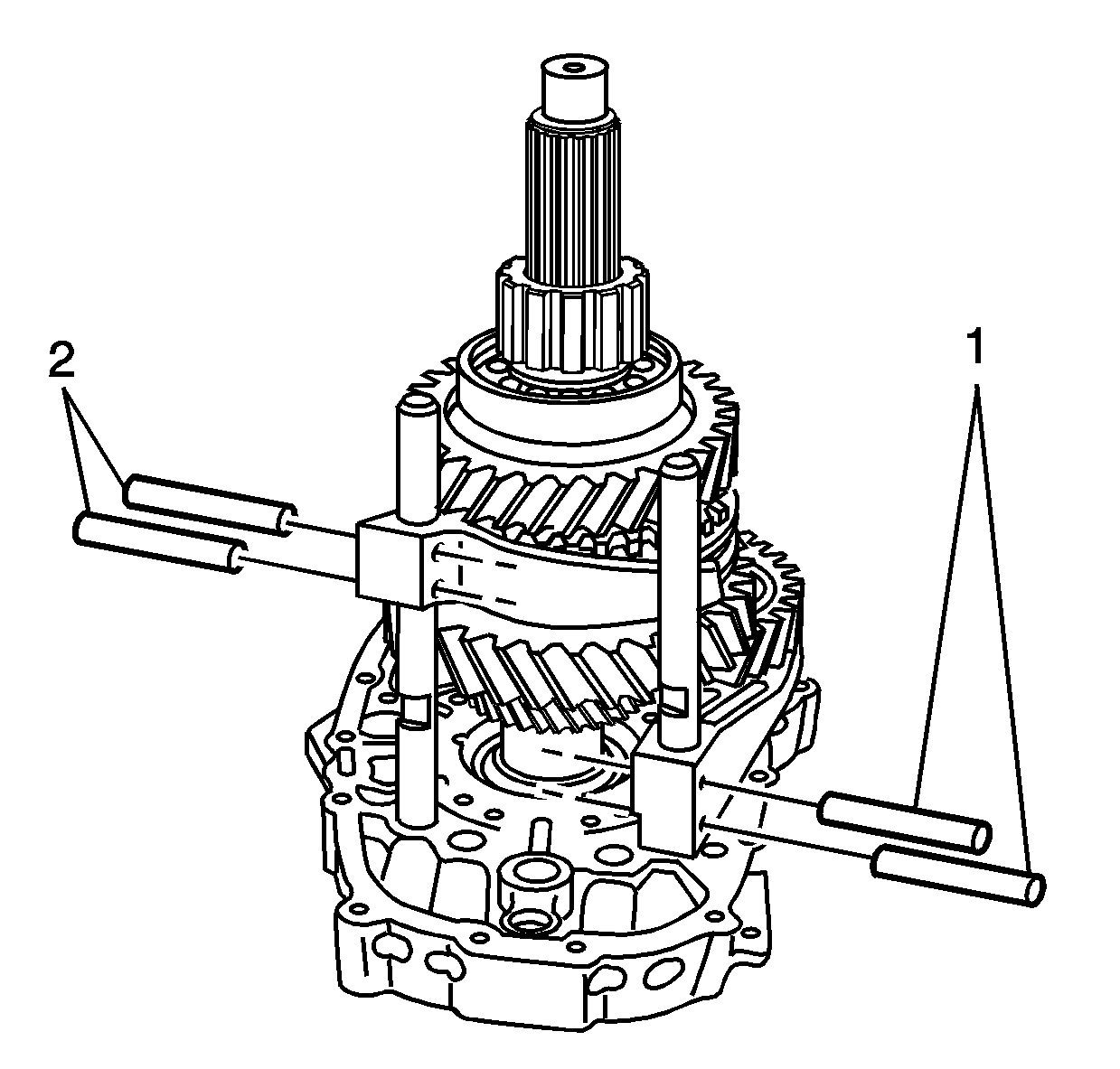
- Install the NEW roll pins
in the 6th gear shift fork (2). A roll pin goes in each hole.
- Install the NEW roll pins in the 1st/reverse gear shift fork (1).
A roll pin goes in each hole.

- If removed, install the
shift block on the main shift rail.
| 34.1. | The part numbers on the shift block, and the part number on the
shift rail, face the same direction. |
| 34.2. | Install the NEW large diameter roll pin. |
| 34.3. | Install the NEW small diameter roll pin, with the roll pin split
180 degrees from the large roll pin split. |

- Install the front internal
shift lever on the main shift rail.
| • | Align the roll pin or lever end, toward the part numbered end
of the shift rail. |
| • | Do not install the roll pins. |
- With the part numbered end pointing up, install the main shift
rail.

- Align the shift block
teeth on the main shift rail with the shift interlock plate.
The center tooth on the shift block will install between the two teeth on
the shift interlock plate.
- Position the front internal shift lever to align with the notch
in the 2nd/3rd shift rail.

- Install the NEW roll pins
in the internal shift control front lever.
| 39.1. | Install the large diameter roll pin. |
| 39.2. | Align the split on the roll pin away from the transmission. |
| 39.3. | Install the small diameter roll pin inside of the large diameter
roll pin. |
| 39.4. | Align the split on the roll pin toward the transmission. |

- Install the internal shift
control rear lever on the main shift rail.

- Align the levers on the
internal shift control rear lever with the slots in the 1st/reverse gear
shift rail and the 6th gear shift rail.
- Install the NEW roll pins in the internal shift control rear lever.
| 42.1. | Install the large diameter roll pin. |
| 42.2. | Align the split on the roll pin away from the transmission. |
| 42.3. | Install the small diameter roll pin inside of the large diameter
roll pin. |
| 42.4. | Align the split on the roll pin toward the transmission. |

- Install the shift shaft
detent plungers and springs.
- Apply a thin layer of gasket maker GM P/N 12378517
(Canadian P/N 88900757) to the shift shaft detent caps.
- Using an 11 mm (27/64 in) punch, install
the shift shaft detent caps.

- Shift the transmission
into 5th gear in order to lock the input shaft to the mainshaft.

- Install S-hooks
and chain to the intermediate case.
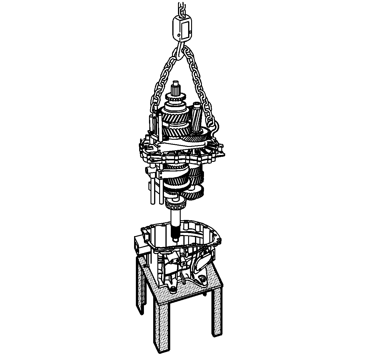
- Position the front case
on the J 45279
in order
to allow the protrusion of the input shaft.
- Using a suitable lifting device, install the gear assembly to
the front case.
| • | Lower the gear assembly slowly in order to align the intermediate
case dowel pins with the front case. |
| • | Do not use a sealer at this time. |

- Install the two intermediate
to front case bolts.
Tighten
Tighten the intermediate case bolts to 23 N·m (17 lb ft).

- Assemble the J 44739
to the intermediate case, to measure
the countershaft preload.
| 51.1. | Install the crosspiece so that the 2 holes are closer to
the single bolt hole upright in the lowest notch. Do not tighten the thumbscrew. |
| 51.2. | Install the crosspiece to the 2 bolt hole upright in the
lowest notch. Do not tighten the thumbscrew. |
| 51.3. | Using a case bolt, install the single bolt hole upright to the
7th case bolt hole from the top, on the right side of the case. |
| 51.4. | Using a case bolt in the hole away from the upright, install the
2 bolt hole upright to the 5th case bolt hole from the top, on the
left side of the case. |
| 51.5. | Tighten the crosspiece thumbscrews. |

- Use the following procedure
in order to measure the countershaft bearing clearance.
| 52.3. | Using a suitable prying tool, lift up the countershaft. |
| 52.4. | Record the dial indicator reading. This is the countershaft bearing
clearance. |
- Using the following formula, establish the shim thickness required
for the countershaft bearing preload:
| 53.1. | Add the mainshaft preload specification 0.02-0.09 mm
(0.0008-0.0035 in) to the countershaft bearing clearance
measurement. |
| 53.2. | The total is the shim thickness required under the countershaft
bearing race in order to set the bearing preload. |
Example
| • | 1.8 mm (0.070 in) mainshaft bearing clearance measurement |
| • | Plus 0.02-0.09 mm (0.0008-0.0035 in)
countershaft preload specification |
| • | Equals 1.82-1.89 mm (0.070-0.074 in)
shim thickness required |

- Assemble the J 44739
to the intermediate case, to measure
the mainshaft preload.
| 54.1. | Install the crosspiece so that the 2 holes are closer to
the single bolt hole upright in the upper notch, for RWD, or center notch
for 4WD. Do not tighten the thumbscrew. |
| 54.2. | Install the crosspiece to the 2 bolt hole upright in the
upper notch, for RWD, or center notch for 4WD. Do not tighten the thumbscrew. |
| 54.3. | Using a case bolt, install the single bolt hole upright to the
3rd case bolt hole from the top, on the right side of the case. |
| 54.4. | Using a case bolt in the hole closest to the upright, install
the upright with the 2 bolt holes to the 6th case bolt hole from
the top, on the left side of the case. |
| 54.5. | Tighten the thumbscrews. |

- Use the following procedure
in order to measure the mainshaft bearing clearance.
| 55.3. | Using a suitable prying tool, lift up the mainshaft. |
| 55.4. | Record the dial indicator reading. This is the mainshaft bearing
clearance measurement. |
- Using the following formula, establish the shim thickness required
for the mainshaft bearing preload:
| 56.1. | Measure the input shaft bearing oil deflector thickness. Record
this measurement. |
| 56.2. | Subtract the oil deflector measurement from the mainshaft bearing
clearance measurement. |
| 56.3. | Add the mainshaft preload specification 0.02-0.09 mm
(0.0008-0.0035 in). |
| 56.4. | The total is the shim thickness required under the input bearing
race in order to set the bearing preload. |
Example
| • | 0.50 mm (0.020 in) oil deflector thickness |
| • | minus 2.2 mm (0.087 in) mainshaft bearing clearance
measurement |
| • | equals 1.7 mm (0.067 in) |
| • | plus 0.02-0.09 mm (0.008-0.0035 in)
mainshaft preload specification |
| • | equals 1.75 mm (0.069 in) shim thickness required |

- Remove the 2 bolts
retaining the intermediate case to the front case.

- Using S-hooks,
a chain, and a suitable lifting device, remove the gear assembly.

- Using the J 44736
(1) and the J 44733
(2), remove the mainshaft front
bearing race.
| 59.1. | Expand the J 44733
(2) to fit securely under the bearing race. |
| 59.2. | Align the legs of the J 44733
to rest on the webbing of the case. |
| 59.3. | Remove the mainshaft front bearing race. |

- Using the J 44736
(1) and the J 44728
(2), remove the countershaft
front bearing race.
| 60.1. | Install the J 44728
(2) in order for the fingers to fit in the notches in the
case. |
| 60.2. | Expand the J 44728
(2) to fit securely in the bearing race. |
| 60.3. | Align the legs of the J 44736
to rest on the webbing of the case. |
| 60.4. | Remove the countershaft front bearing race. |

- Using the J 25070
, heat the front case for 10-15 minutes.

- Install the required shims
for the countershaft bearing preload.

Important: Install the bearing races with the front case still hot. Do not allow
the front case to cool.
- Using the J 8092
(1),
the J 21465-13
(2),
and the J 44745
(3),
install the countershaft front bearing race.

- Install the oil trough.

- Install the required shims
for the mainshaft bearing preload.
- Install the input shaft gear oil deflector.

- Using the J 8092
(1), the J 21465-13
(2), and the J 44746
(3), install the mainshaft front
bearing race.
- Allow the front case to cool.

- Apply a thin layer of
gasket maker GM P/N 12378517 (Canadian P/N 88900757)
to the sealing surface of the front case.
- Using a suitable lifting device, install the gear assembly to
the front case.

- Install the two intermediate
case to front case bolts.
Tighten
Tighten the intermediate case to front case bolts to 23 N·m
(17 lb ft).
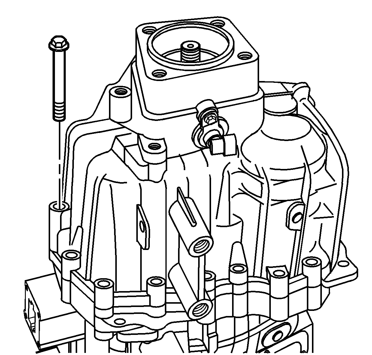
- Apply a thin layer of
gasket maker GM P/N 12378517 (Canadian P/N 88900757)
to the sealing surface of the rear case.
- Install the rear case on to the intermediate case.
- Using a soft-face hammer, tap down on the rear case to
seat the dowel pins. Do not use the bolts to draw the case together.
- Install the required brackets and the bolts retaining the rear
case.
Tighten
Tighten the rear case bolts in a crossover sequence to 23 N·m
(17 lb ft).

- Apply a thin layer of
threadlocker GM P/N 12345382 (Canadian P/N 10953489)
to the threads of the shift shaft detent sleeve.
- Install the shift shaft detent plunger and sleeve.
Tighten
Tighten the detent sleeve to 65 N·m (48 lb ft).
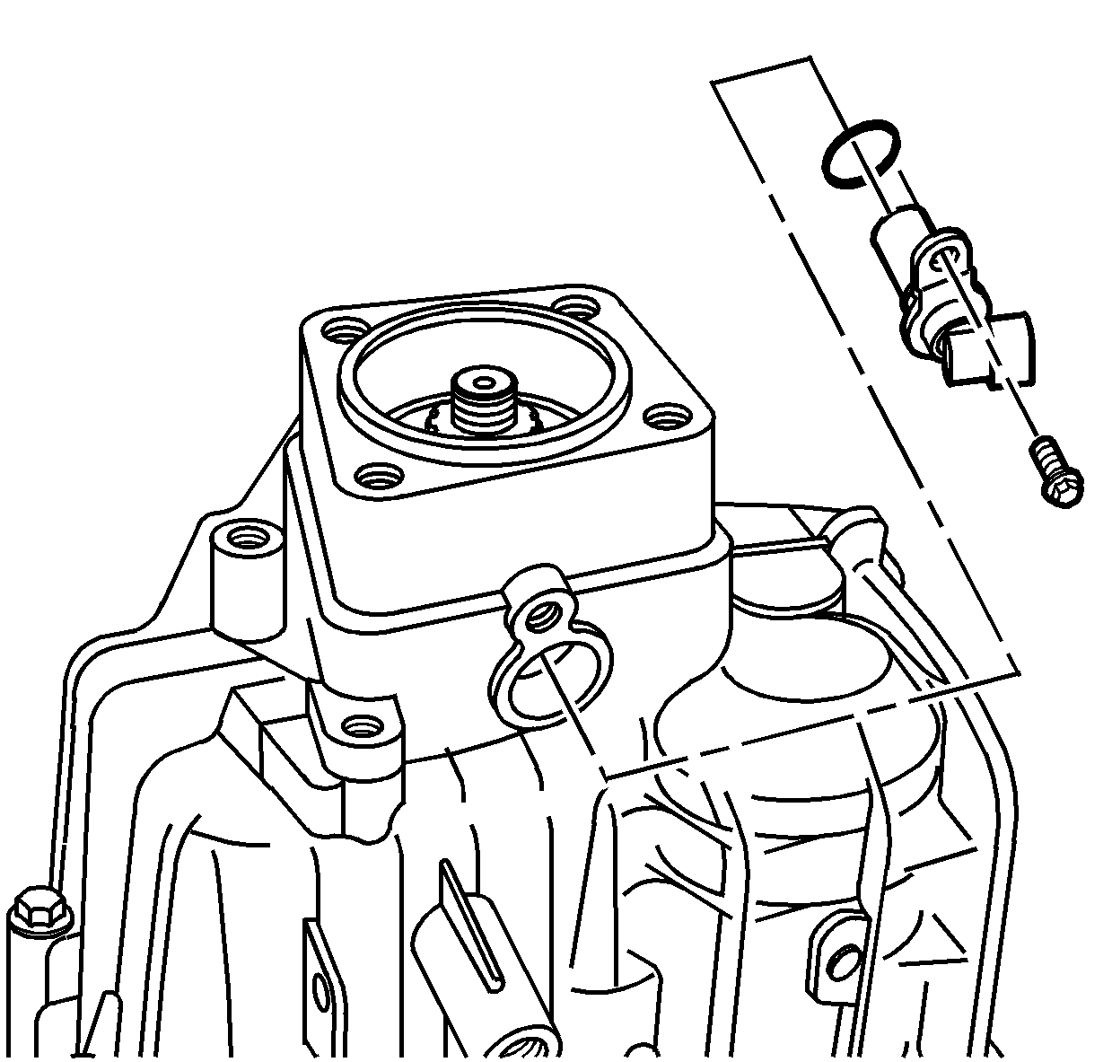
- Install the vehicle speed
sensor (VSS) with an O-ring seal in the rear case.
- Install the VSS bolt.
Tighten
Tighten the VSS bolt to 20 N·m (15 lb ft).
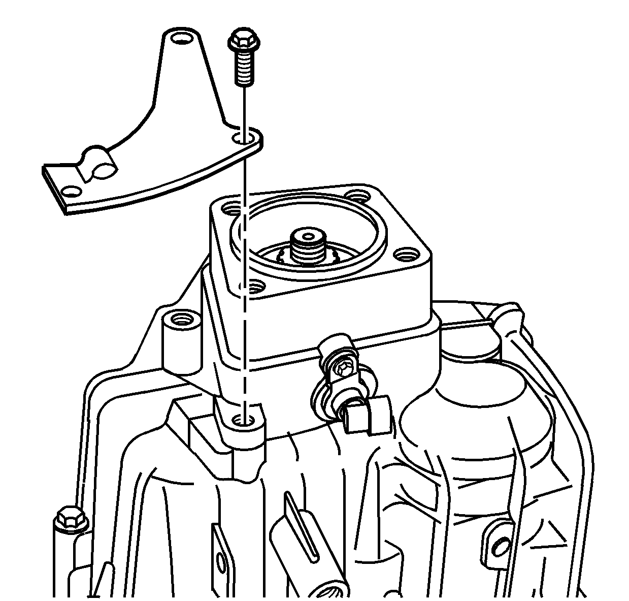
- Install the parking brake
cable bracket.
- Install the bolts retaining the parking brake cable bracket.
Tighten
Tighten the bracket bolts to 23 N·m (17 lb ft).
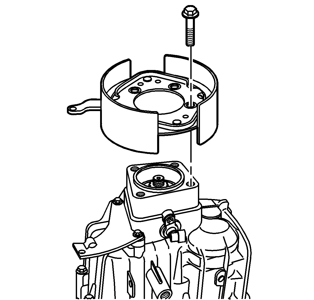
- Lubricate the hole for
the parking brake cam lever in the case with chassis grease.
- Install, as an assembly, the parking brake shoes, bracket, and
cam lever.
- Install the bolts retaining the parking brake shoe bracket to
the rear case.
Tighten
Tighten the shoe bracket bolts to 120 N·m (89 lb ft).
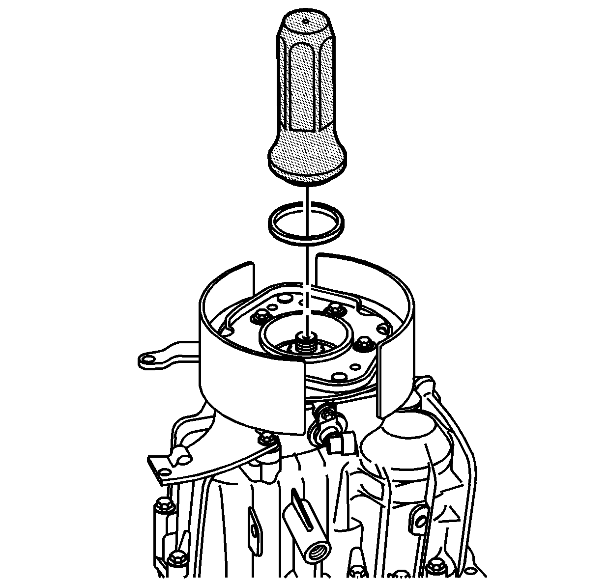
- Using the J 44732
, install the rear oil seal. The seal
installer will install the seal at the correct depth.
- Lightly lubricate the seal surface with J 36850
or equivalent.
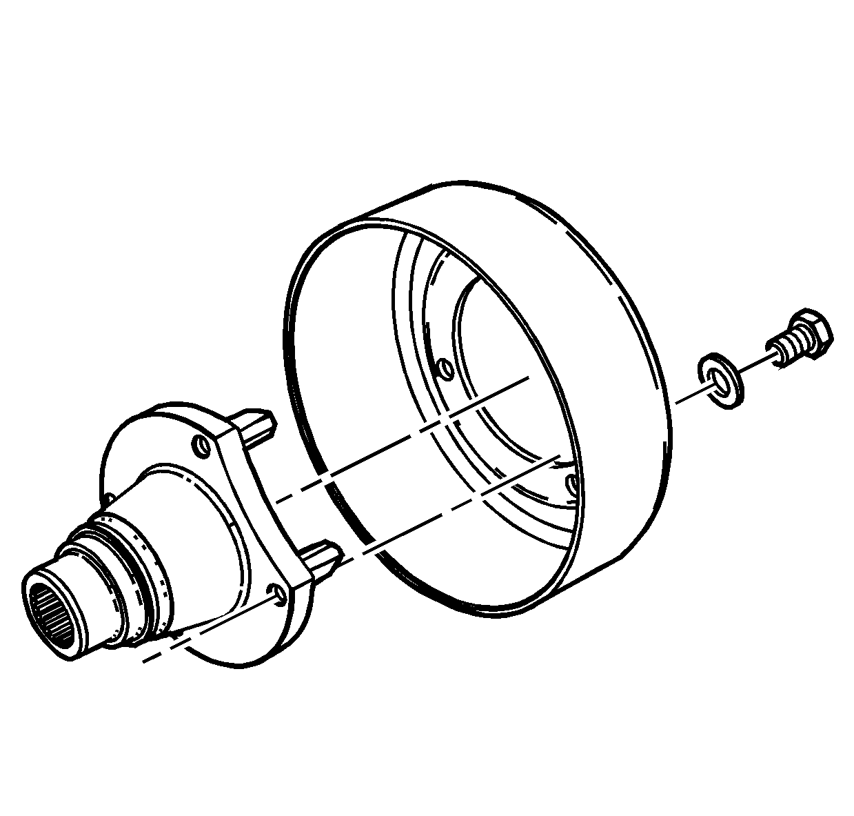
Important:
| • | The original drum and yoke come as a balanced assembly. Ensure to align
the mark during disassembly, if using the drum and yoke again. |
| • | The transmission may have a 4 bolt parking brake drum/yoke assembly
or an 8 bolt parking brake/drum yoke assembly. The assembly procedures
to install the drum/yoke assembly are the same. |
- If removed, install the parking brake drum to the propeller shaft yoke.
- Install the parking brake drum to propeller shaft yoke bolts.
Tighten
| • | Tighten the 4 bolt drum bolts to 145 N·m (107 lb ft). |
| • | Tighten the 8 bolt drum bolts to 60 N·m (44 lb ft). |
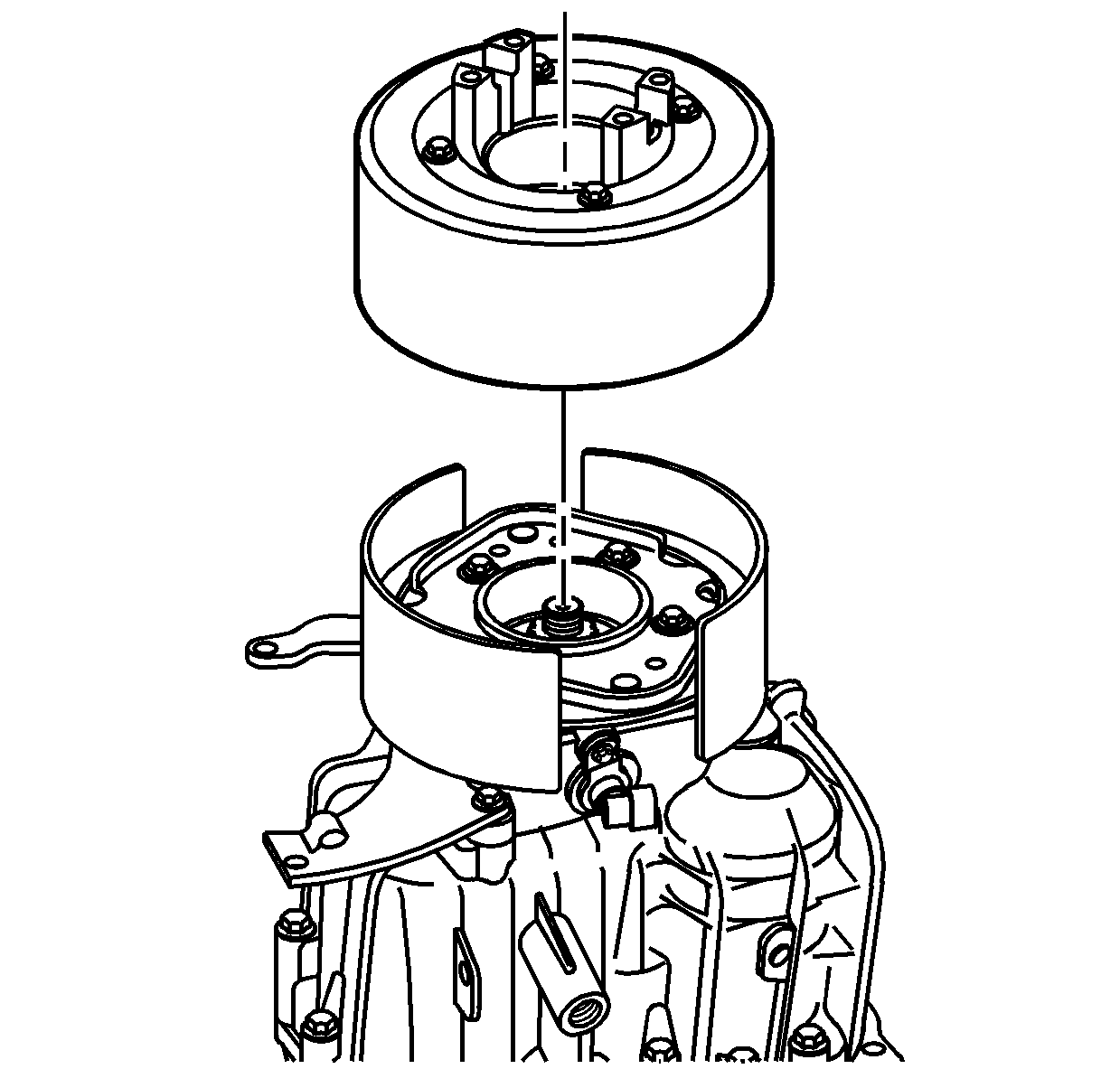
- Install the parking brake
drum/yoke assembly.
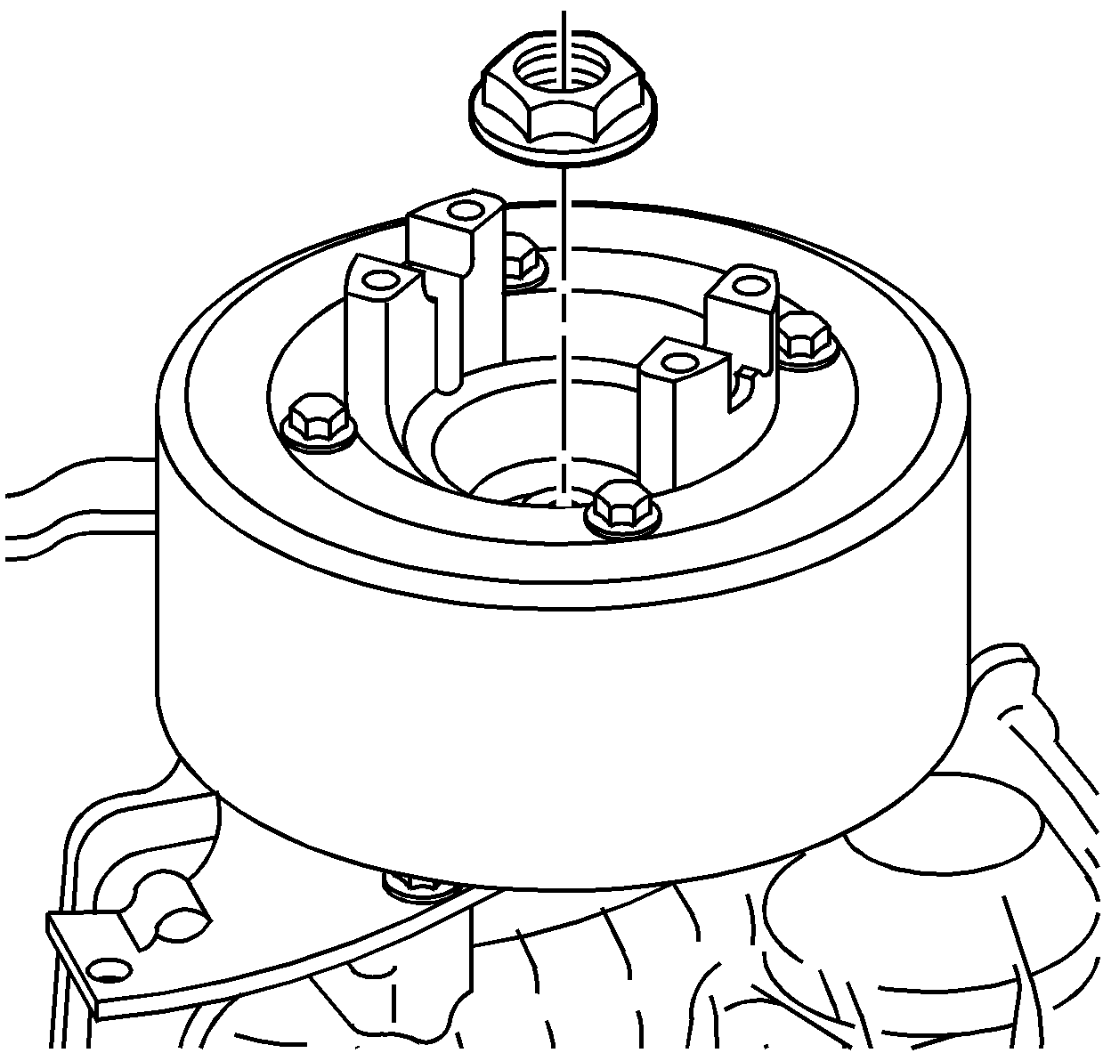
- Install a NEW propeller
shaft yoke nut.
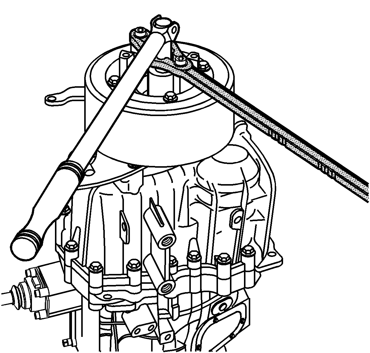
- Install the J 8614-01
in order to hold the transmission
shaft from rotating. Use 2 3/8 inch NF bolts to hold
the J 8614-01
to the propeller
shaft yoke.
Tighten
Tighten the NEW propeller shaft yoke nut to 330 N·m (244 lb ft).
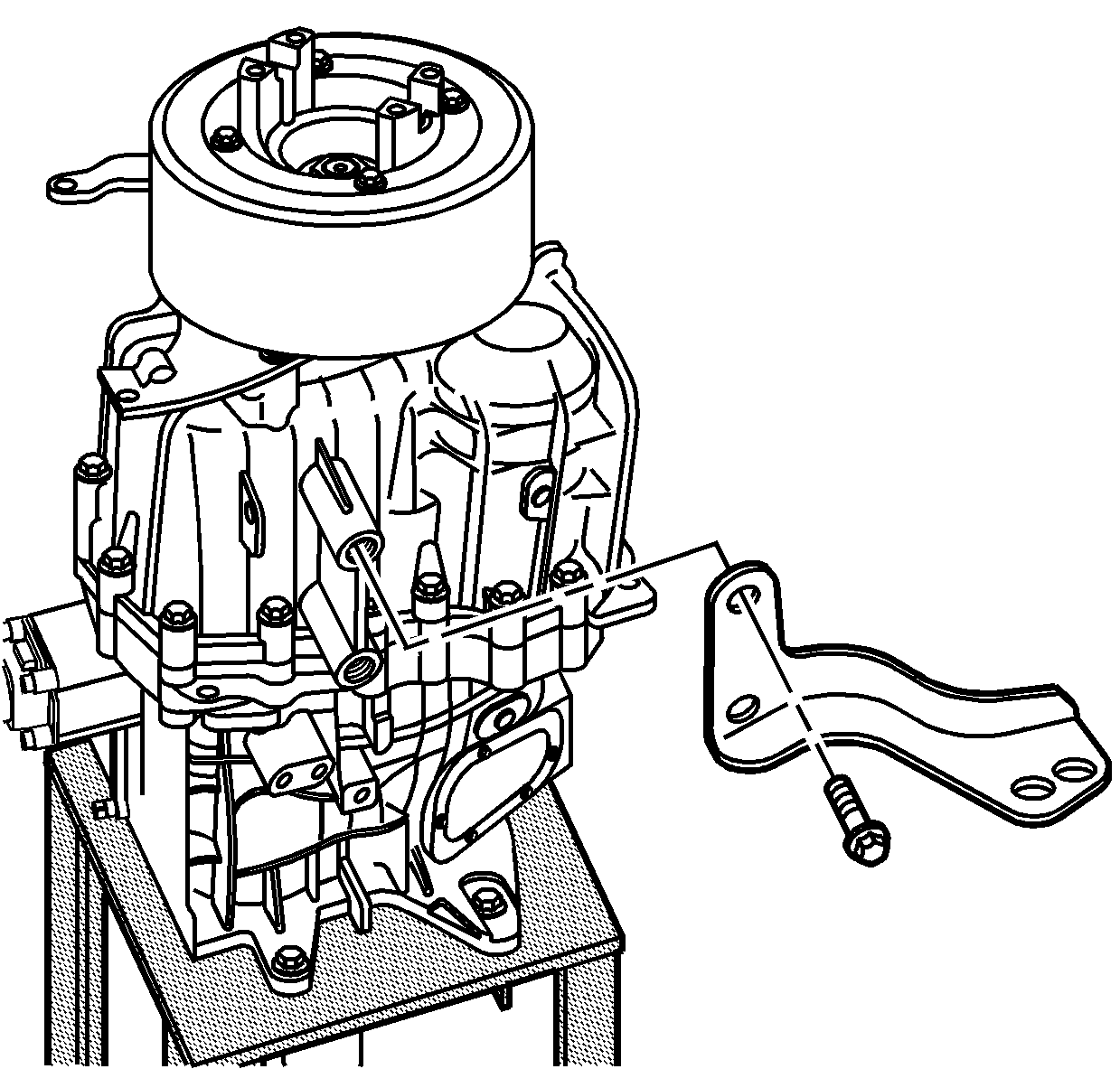
- Install the clutch cable
bracket and the bolts.
Tighten
Tighten the clutch cable bracket bolts to 46 N·m (34 lb ft).
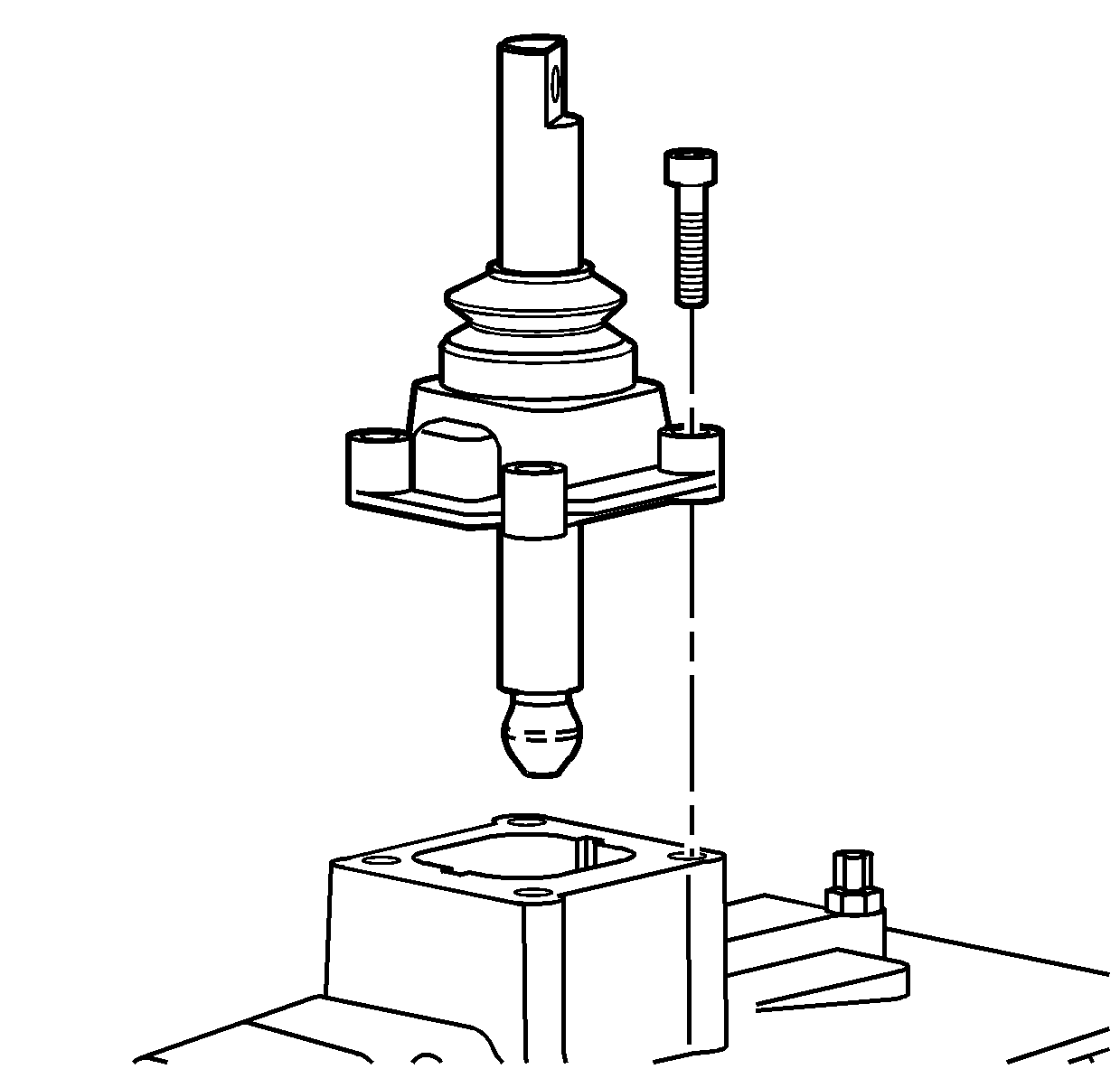
- If the lower shift lever
requires installation before installing in the vehicle, apply a thin layer
of gasket maker GM P/N 12378517 (Canadian P/N 88900757)
to the sealing surface of the lower shift control lever.
- Install the lower shift control lever. Ensure the word FRONT on
the shift control housing is to the front of the transmission.
- Install the lower shift control lever bolts.
Tighten
Tighten the lower shift control lever bolts to 23 N·m (17 lb ft).
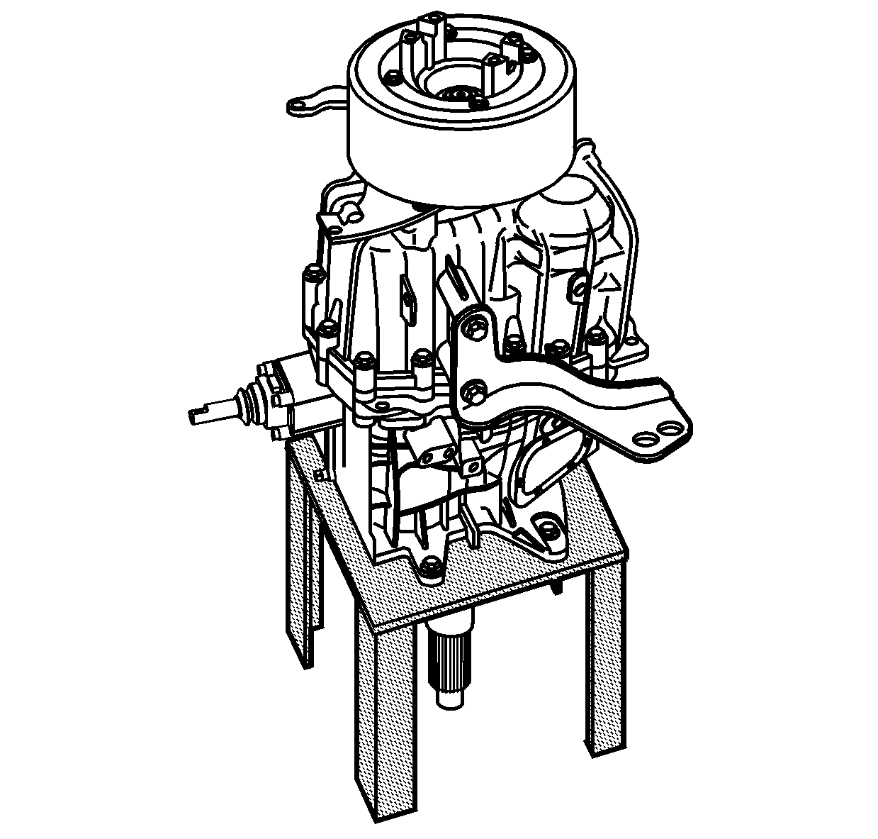
- Move the transmission
to the horizontal position.
- Remove the J 45279
from the front of the transmission.
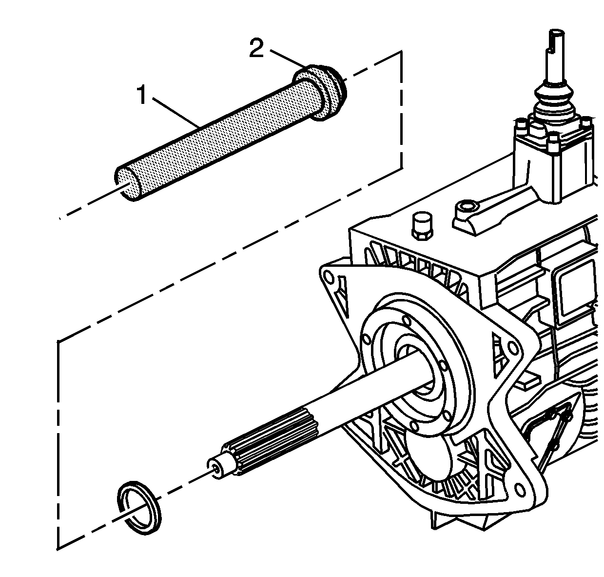
Important: When installing the input shaft seal, there is not a stop for the seal
in the case. Using the seal tools will install the seal at the proper
depth. Hitting too hard on the seal tools can misplace the seal at the
proper depth.
- Using the J 22828
and the J 45277
, install
the input shaft seal.
| 98.1. | Position the seal in the front case with the open side to the
transmission. |
| 98.2. | Lightly tap on the J 22828
to install the seal. |
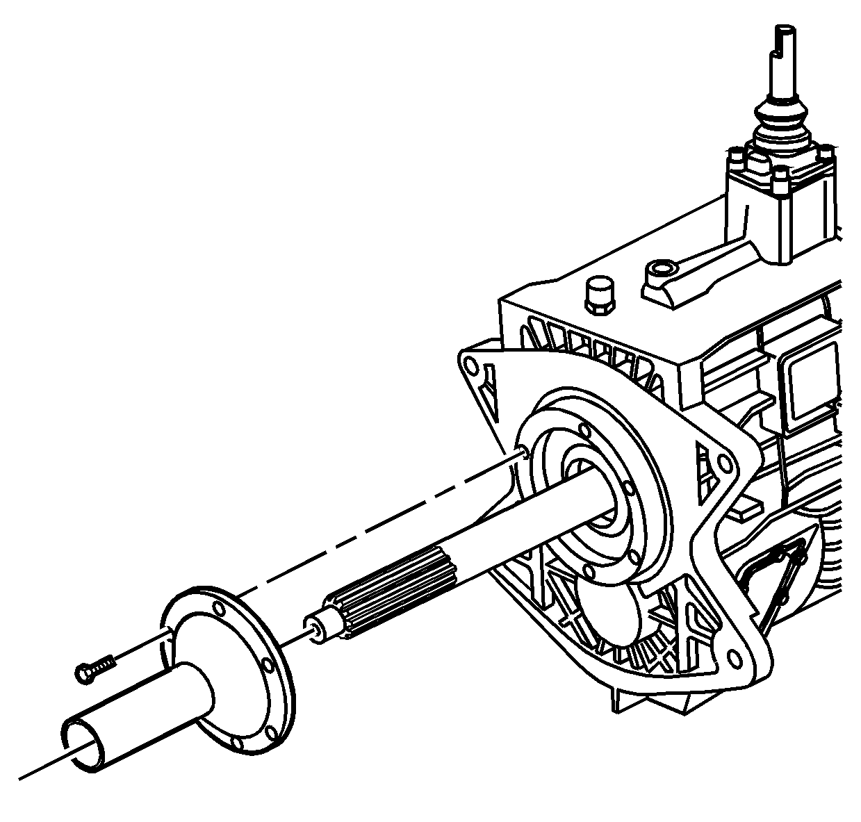
- Install the quill tube.
- Install the 6 bolts holding the quill tube to the front
of the transmission.
Tighten
Tighten the quill tube bolts to 23 N·m (17 lb ft).
- Shift the transmission through all of the gears to ensure proper
shifting.
- Rotate the transmission by the input shaft.
There
should be resistance to turn.
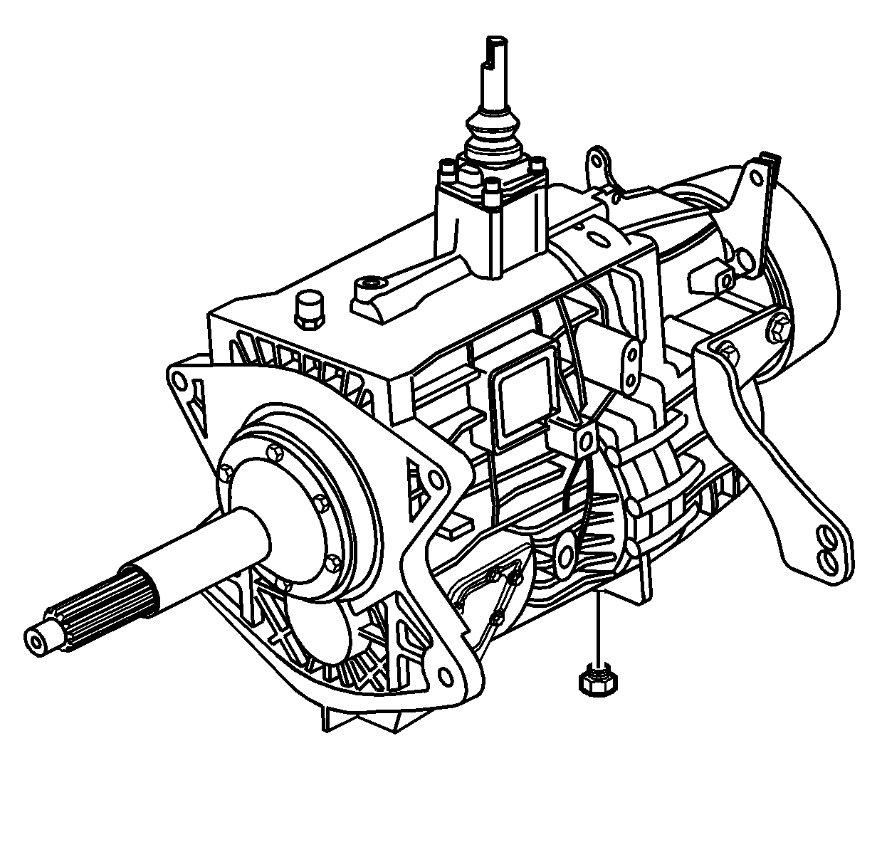
- Install the transmission
drain plug and O-ring seal. Ensure the O-ring seal is not
damaged.
Tighten
Tighten the drain plug to 35 N·m (26 lb ft).
- If equipped with a PTO, install the PTO using the manufacturers
recommended procedures for the proper operation.


