Notice: Use the correct fastener in the correct location. Replacement fasteners
must be the correct part number for that application. Fasteners requiring
replacement or fasteners requiring the use of thread locking compound or sealant
are identified in the service procedure. Do not use paints, lubricants, or
corrosion inhibitors on fasteners or fastener joint surfaces unless specified.
These coatings affect fastener torque and joint clamping force and may damage
the fastener. Use the correct tightening sequence and specifications when
installing fasteners in order to avoid damage to parts and systems.
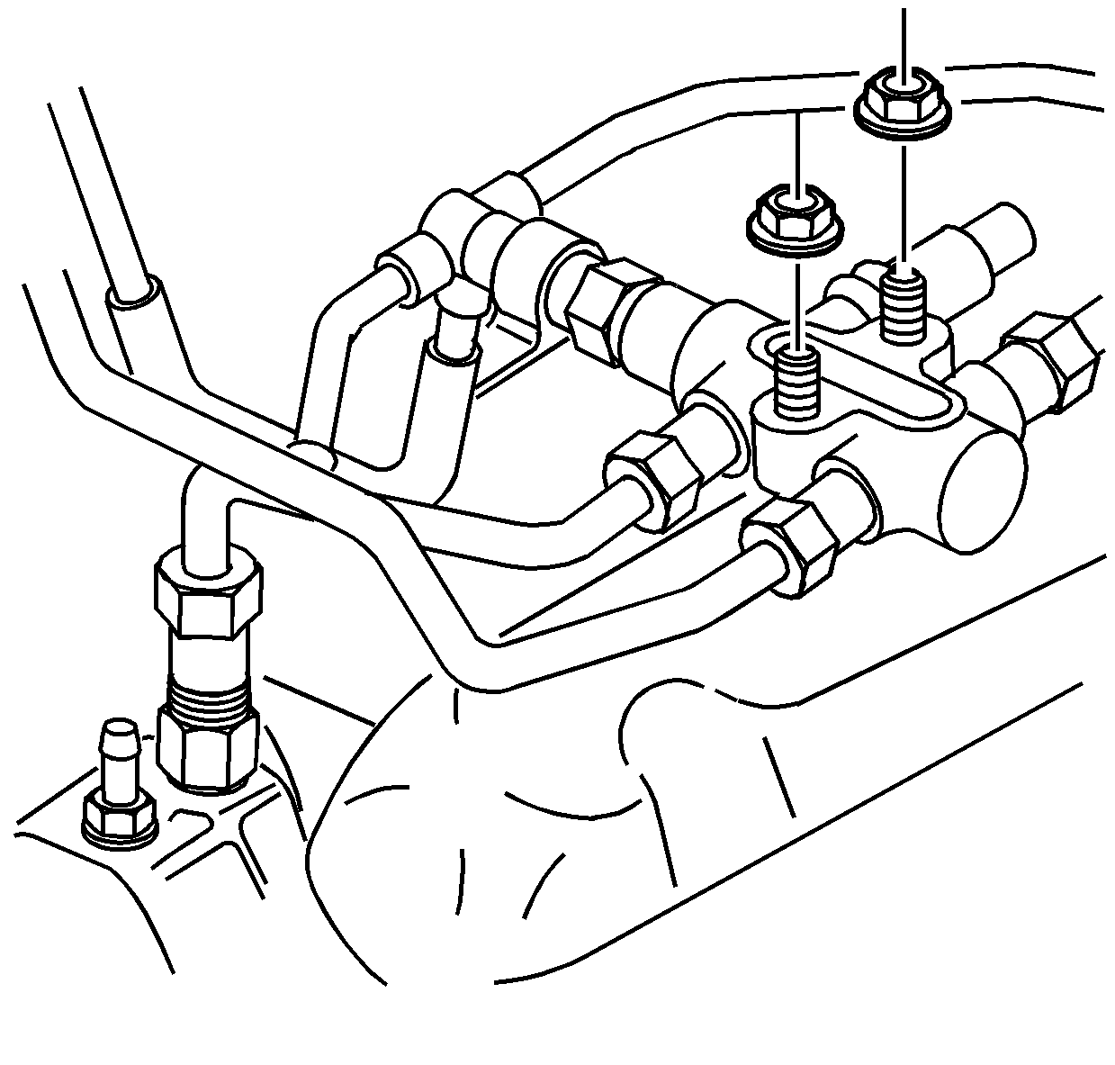
- Install the junction block and the two nuts holding the junction block.
Tighten
Tighten the nuts to 25 N·m (18 Ib ft).
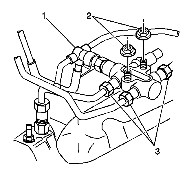
- Install the fuel system return line banjo bolt (1) to the junction block.
Tighten
Tighten the fuel return line banjo bolt to 15 N·m (11 lb ft).
- Connect the three fuel pipes (3) to the junction block.
Tighten
Tighten the high pressure fuel lines to 44 N·m (32 lb
ft).
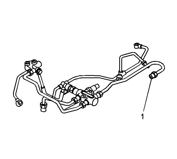
- Connect the other end
of the pipe (1) to the left fuel rail.
Tighten
Tighten the high pressure pipe from the junction block to the left fuel
rail to 44 N·m (32 lb ft).
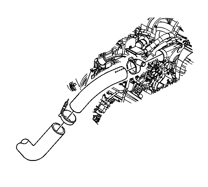
- Install the charged air
cooler inlet duct to turbocharger charged air cooler outlet. Align the marks
on the hose and the intake manifold duct.
Tighten
Tighten the charged air cooler clamp to 6 N·m (53 lb
in).
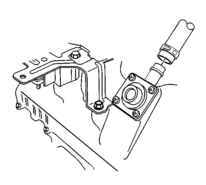
- Install the PCV hose to
the upper valve rocker arm cover.
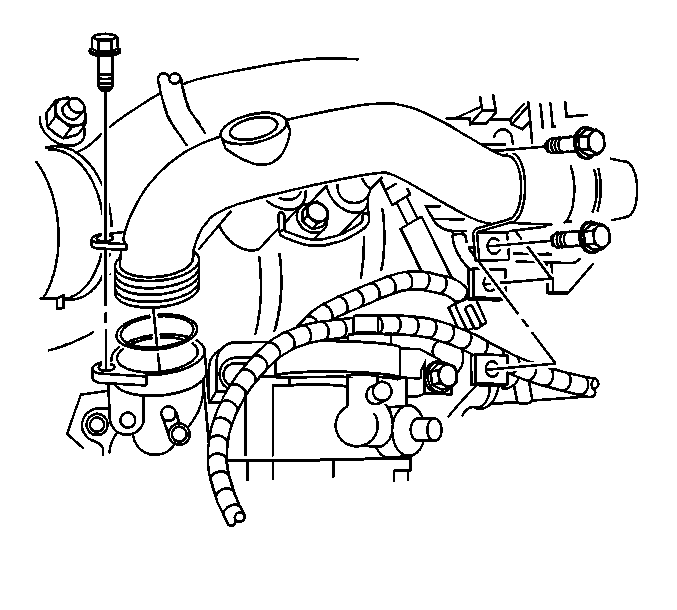
- Install the water outlet
tube using the following procedure:
| 7.1. | Install a new O-ring seal on the water outlet tube. |
| 7.2. | Lightly lubricate the O-ring seal with coolant. |
| 7.3. | Install the water outlet tube. |
| 7.4. | Install the bolt retaining the water outlet tube to the thermostat
housing. |
Tighten
Tighten the water outlet tube to thermostat housing bolt to 21 N·m
(16 lb ft).
| 7.5. | Install the 2 bolts retaining the water outlet tube to the valve
rocker arm cover. |
Tighten
Tighten the water outlet tube to valve rocker arm cover bolts to 21 N·m
(16 lb ft).
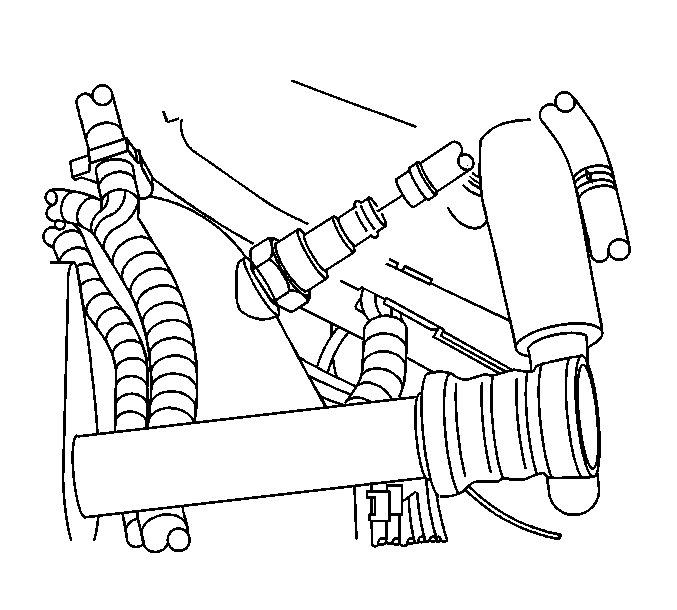
- Install the turbocharger
coolant hose and clamp from the turbocharger bypass valve.
- Connect the oil pressure sending unit harness connector.
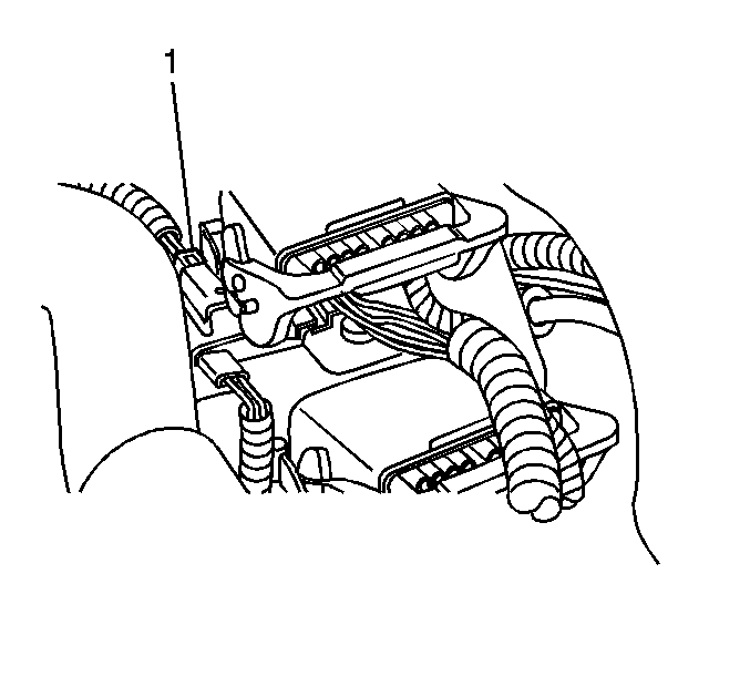
- Connect the left front
injector harness connector (1).
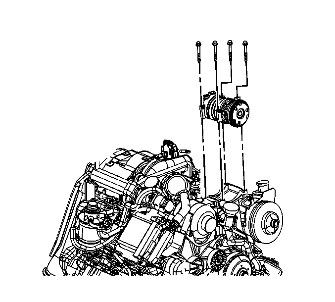
- Install the A/C compressor
using the following procedure:
| 11.1. | Install the A/C compressor mounting bolts. |
Tighten
Tighten the A/C compressor mounting bolts to 50 N·m (37 lb
ft).
| 11.2. | Reconnect the A/C cut out switch electrical connector. |
| 11.3. | Reconnect the A/C compressor clutch electrical connector. |
- Replace the drive belt. Refer to
Drive Belt Replacement
in Engine Mechanical.
- Fill the engine coolant. Refer to
Cooling System Draining and Filling
in Engine Cooling.
- Install the upper intake manifold sight shield.
Tighten
Tighten the upper intake manifold sight shield bolt to 9 N·m
(80 lb in).
- Install the fuel cap.
- Connect the negative batteries cables to both batteries. Refer
to
Battery Negative Cable Disconnection and Connection
in Engine Electrical.
- Position the hood in the normal operating position by moving
the hood hinge bolts from service position (2) to normal operating position
(1).
Tighten
Tighten the bolts to 25 N·m (18 lb ft).
- Purge air from the fuel system. Refer to
Fuel Feed Pipe and Return Pipe Purging
.


