GM Service Manual Online
For 1990-2009 cars only
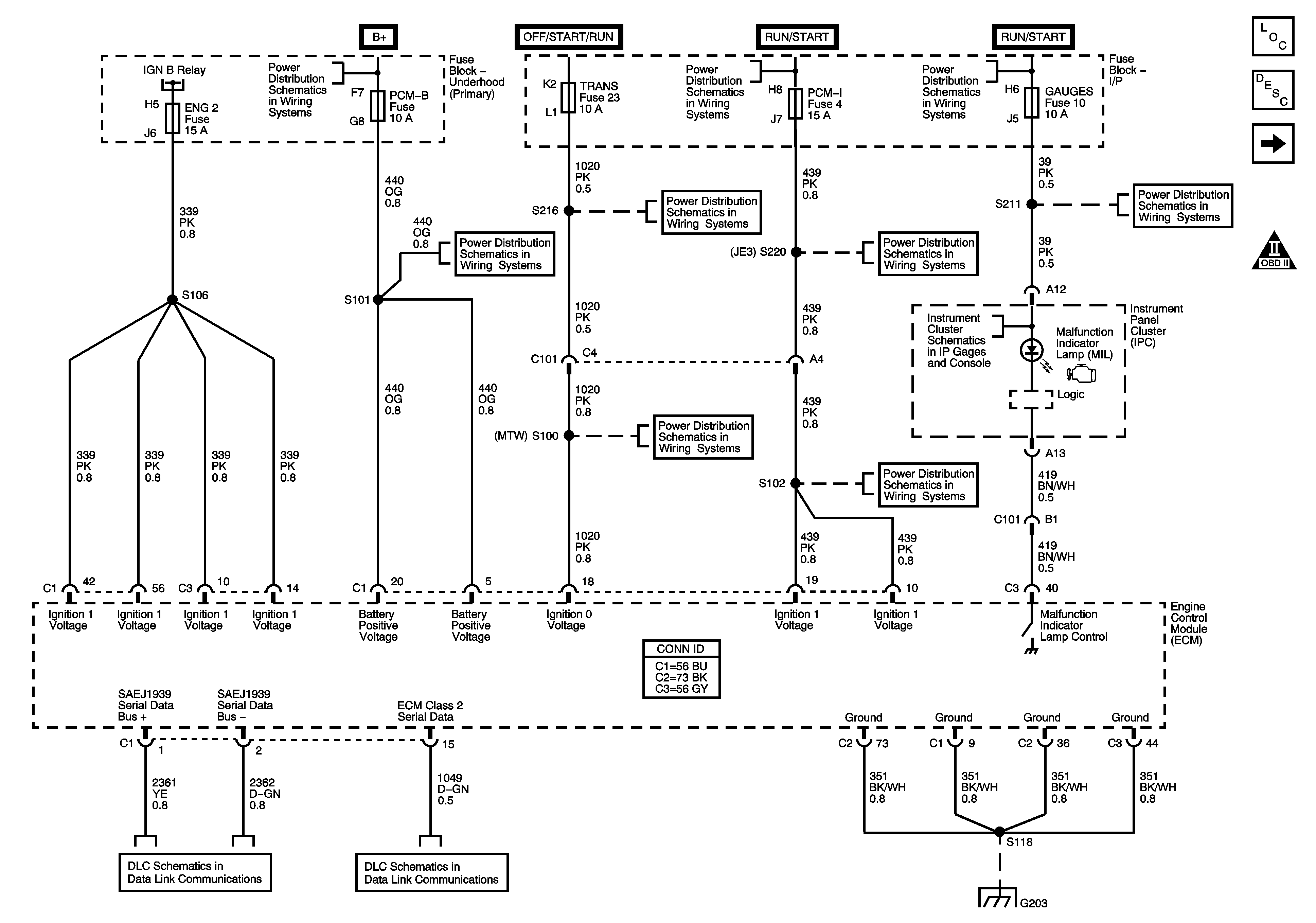
Figure 1:

Module Power, Ground, Serial Data, and MIL

Object Number: 1404947  Size: FS
Master Electrical Component List
Engine Control Module Description
Fuse Block-Underhood Ignition A and B Relays
Engine Controls Schematic Icons
Fuse Block-Underhood Ignition A and B Relays
B+ Bus Bar
Ignition Switch - OFF/RUN/START, RUN/START and START Bus Bars
A/C COMP, HTD FUEL, PCM-B, and RR DEFOG Fuses
START and TRANS Fuses/Circuit Breakers
ENGINE and PCM-I Fuses/Circuit Breakers
GAUGES, L-RR TRUCK, R-RR TRUCK, and SIR Fuses/Circuit Breakers
Power and Indicators
START and TRANS Fuses/Circuit Breakers
ENGINE and PCM-I Fuses/Circuit Breakers
J1939 Serial Data (L65/L18/LG4/LC8) - 2 of 2
Splice Pack SP203 (L18/LB7/LG4/LLY)
G203 - 2 of 4
Figure 2:

Fuse Block - Underhood Ignition A and B Relays
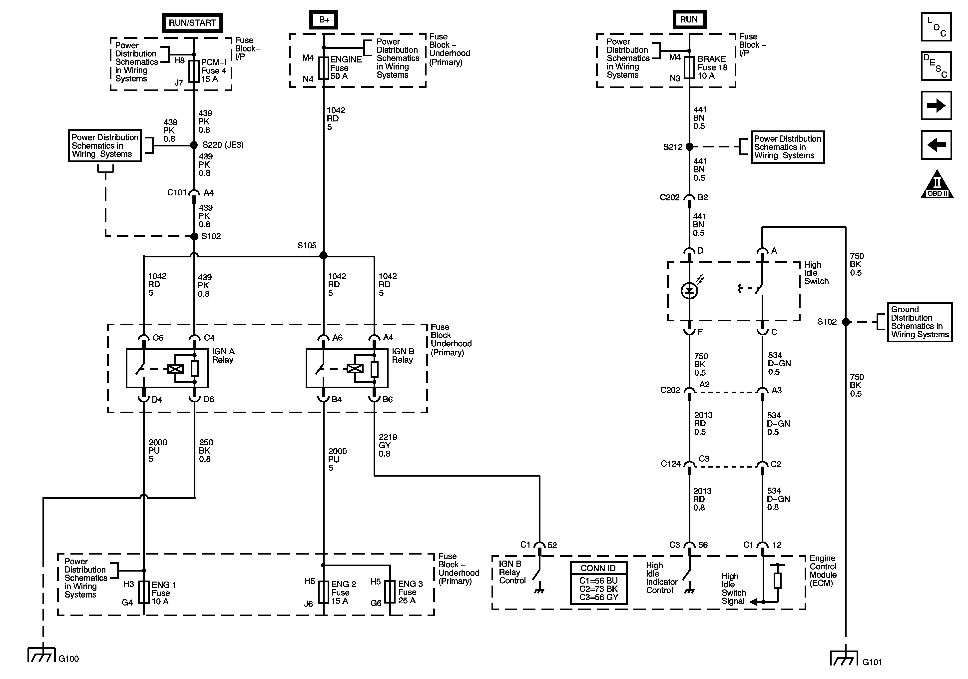

Object Number: 1404953  Size: FS
Master Electrical Component List
Engine Control Module Description
Engine Data Sensors-5 Volt and Low Reference
Module Power,Ground,Serial Data,and MIL
Engine Controls Schematic Icons
Ignition Switch - OFF/RUN/START, RUN/START and START Bus Bars
B+ Bus Bar
Ignition Switch - RUN and ACC/RUN Bus Bars
ENGINE and PCM-I Fuses/Circuit Breakers
AXLE/4WD, BRAKE, CHASSIS, and HTR/AC Fuses/Circuit Breakers
G101 - 1 of 2
G100 (LB7)
G100 (LB7)
G101 - 1 of 2
Figure 3:

Engine Data Sensors - 5-Volt and Low Reference
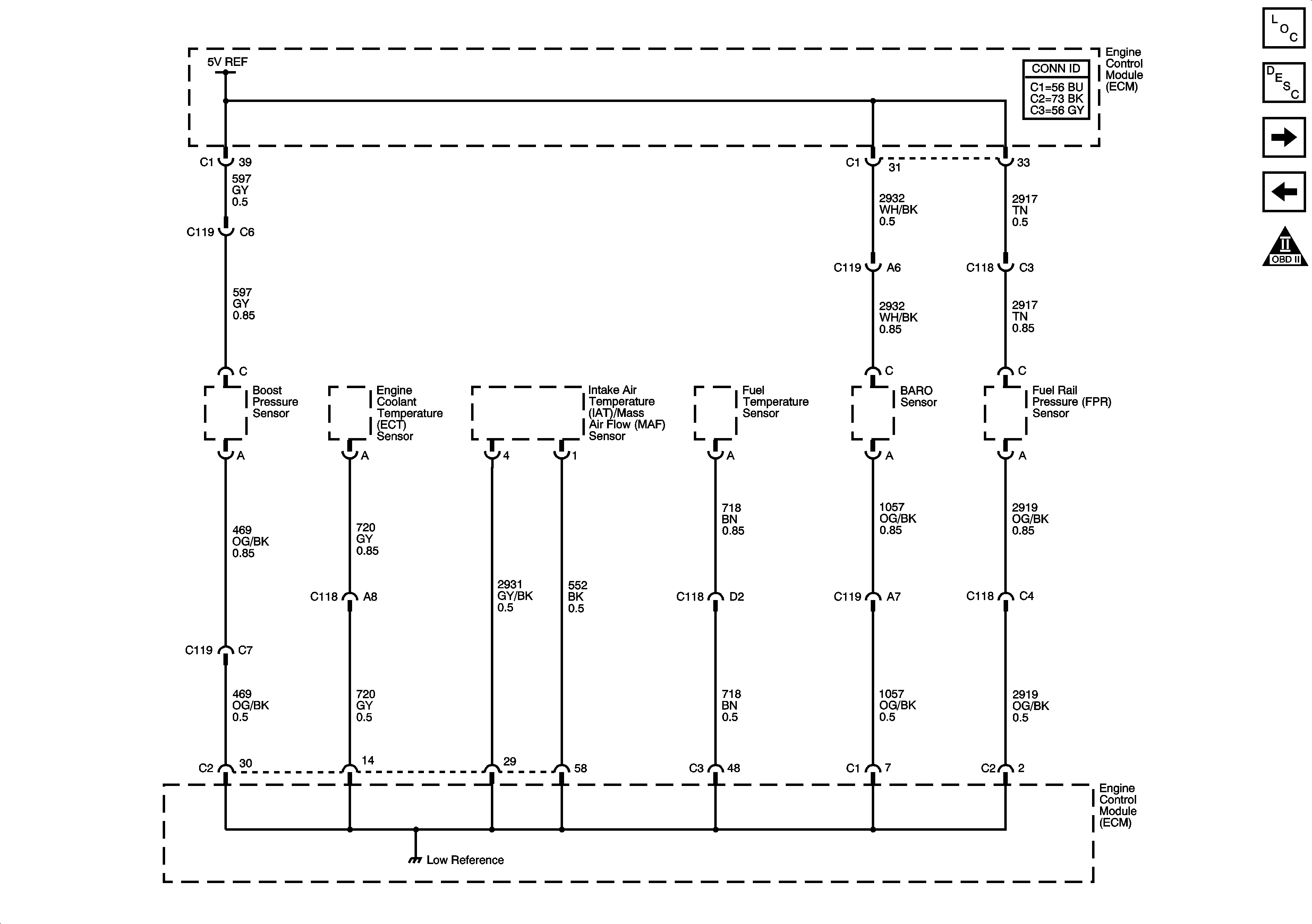

Object Number: 1405268  Size: FS
Master Electrical Component List
Engine Control Module Description
Engine Data Sensors-Pressure, Temperature, and Pedal Position
Fuse Block-Underhood Ignition A and B Relays
Engine Controls Schematic Icons
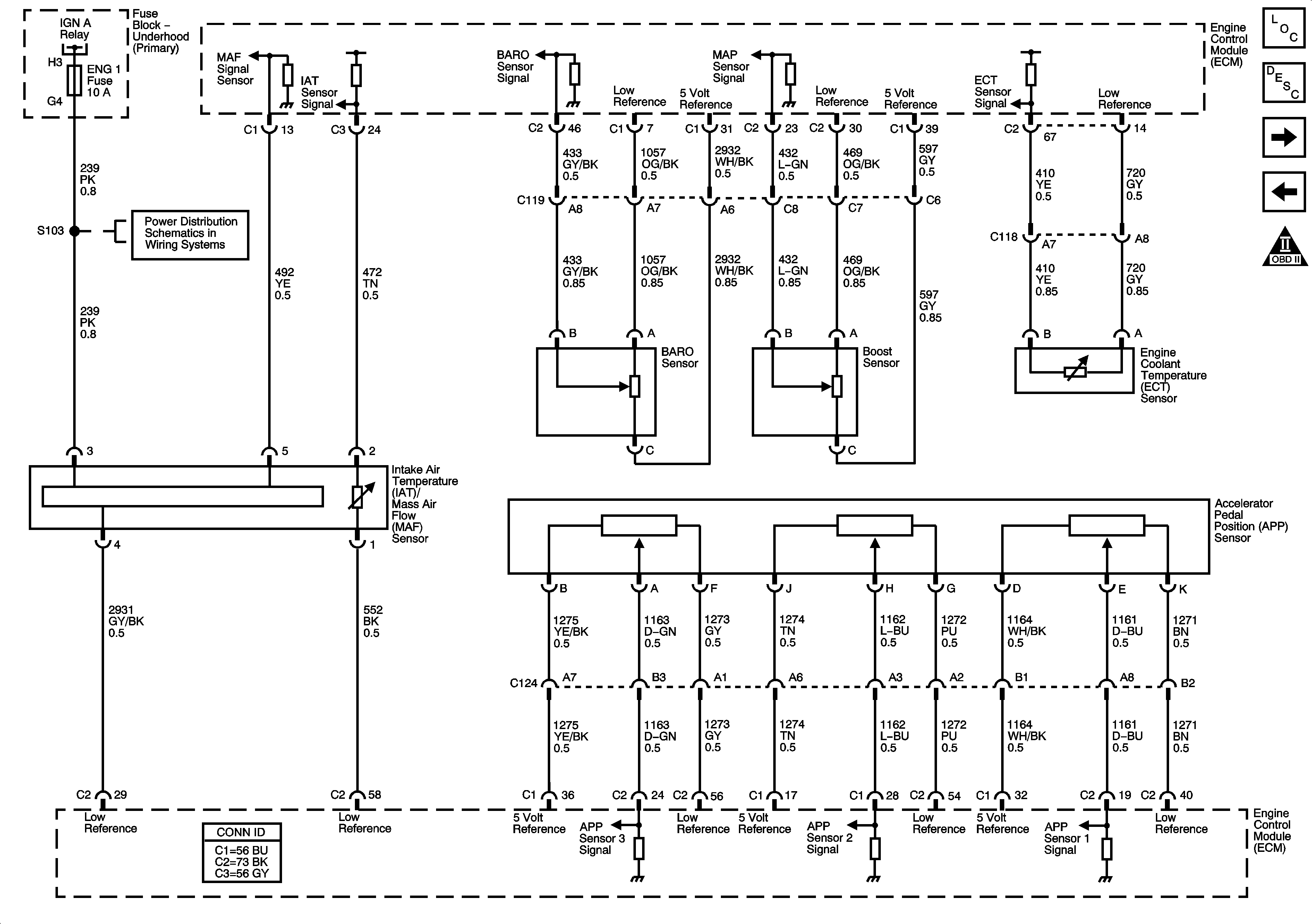
Figure 4:

Engine Data Sensors - Pressure, Temperature, and Pedal Position


Object Number: 1405350  Size: FS
Master Electrical Component List
Air Intake System Description
Engine Data Sensors-Turbocharger and EGR
Engine Data Sensors-5 Volt and Low Reference
Engine Controls Schematic Icons
Fuse Block-Underhood Ignition A and B Relays
ENG 1 and ENG 4 Fuses (L18/LB7)
Figure 5:

Engine Data Sensors - Turbocharger and EGR
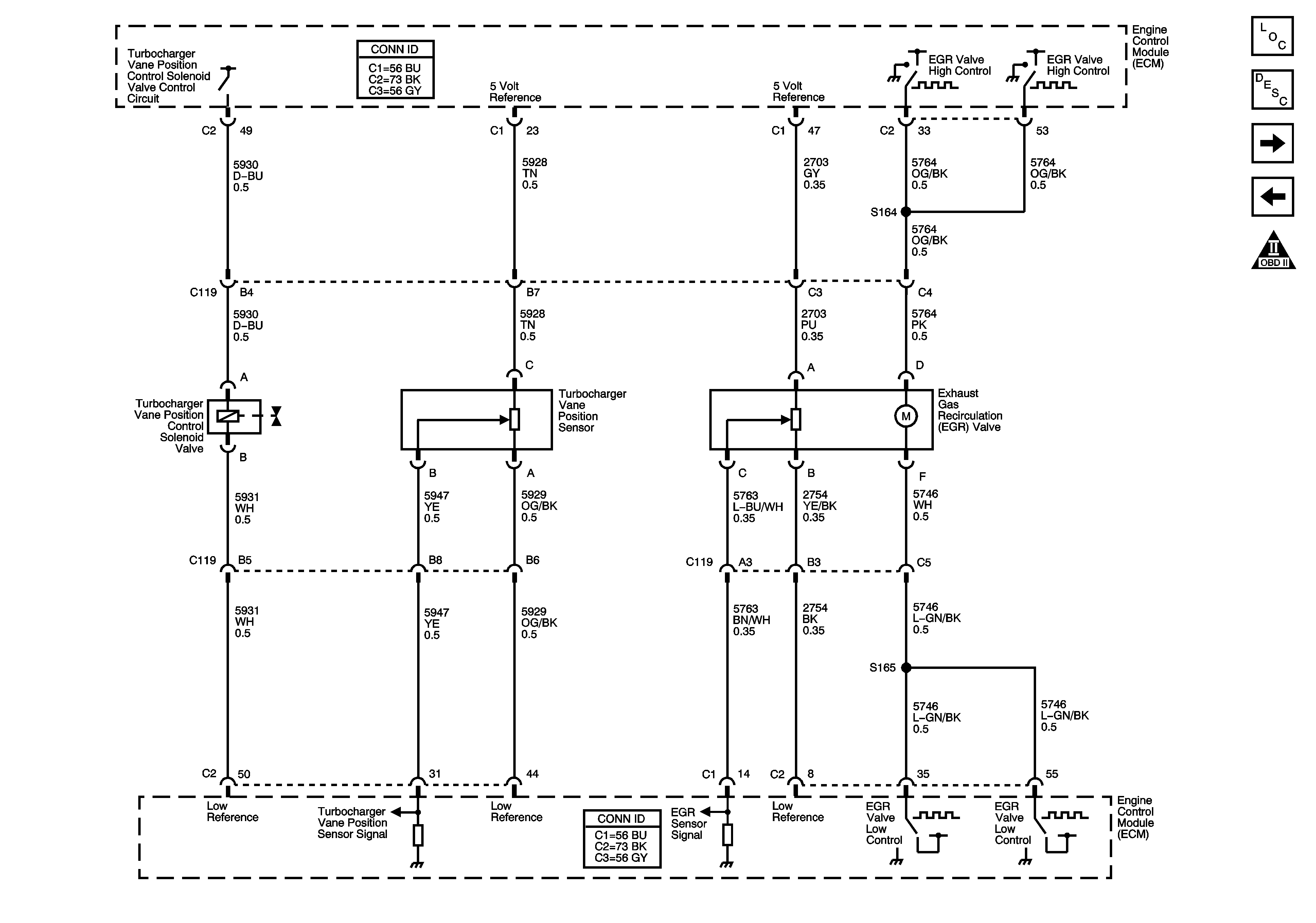

Object Number: 1405362  Size: FS
Master Electrical Component List
Air Intake System Description
Engine Data Sensors-VSS
Engine Data Sensors-Pressure, Temperature, and Pedal Position
Engine Controls Schematic Icons
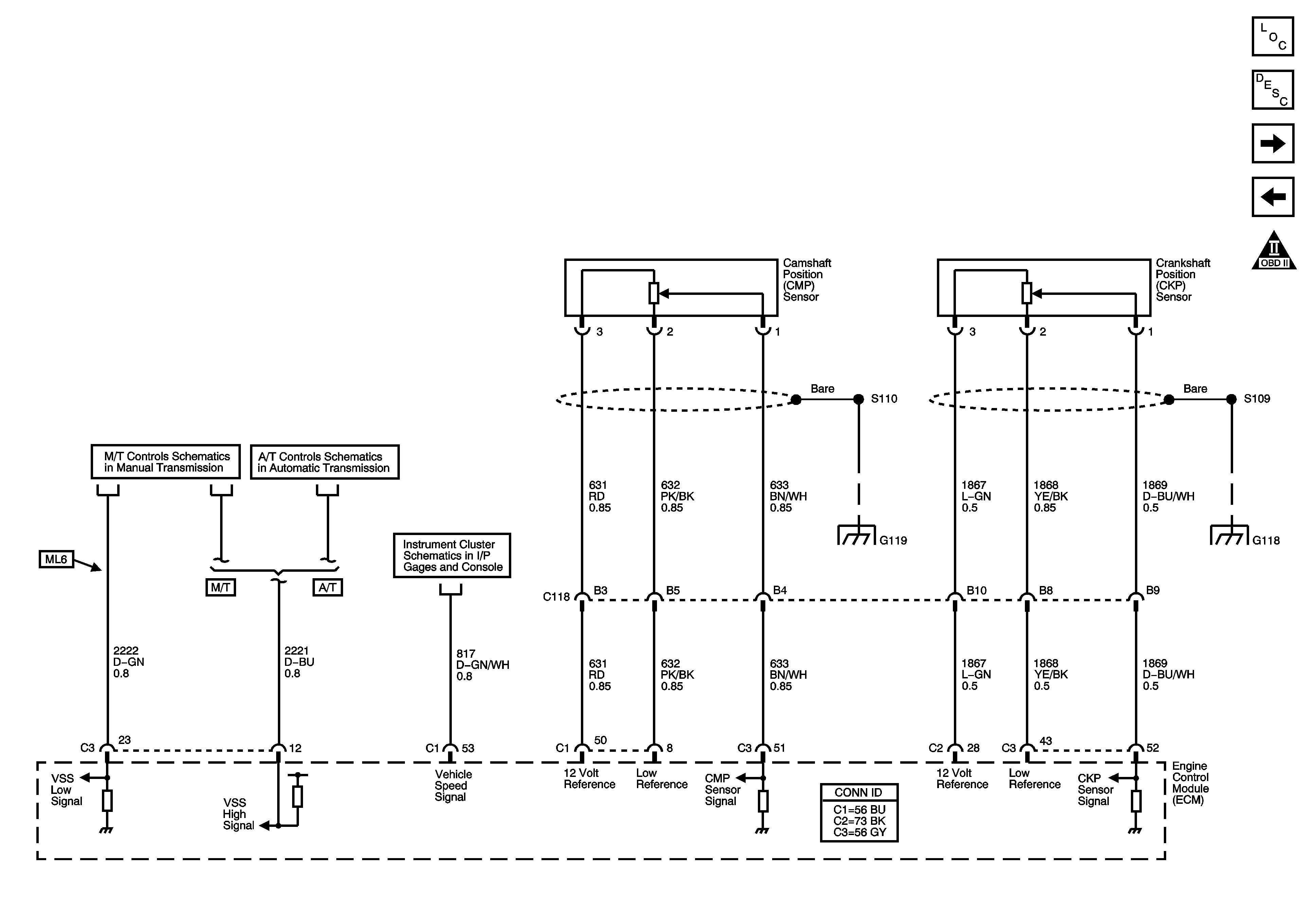
Figure 6:

Engine Data Sensors - VSS


Object Number: 1405394  Size: FS
Master Electrical Component List
Exhaust Gas Recirculation (EGR) System Description
Engine Data Sensors-Injection Timing Controls
Engine Data Sensors-Turbocharger and EGR
Engine Controls Schematic Icons
Manual Transmission
Module Power, Ground, Serial Data, MIL, VSS, and Torque
Ground and Gages
G118, G119, and G120
Figure 7:

Engine Data Sensors - Injection Timing Controls
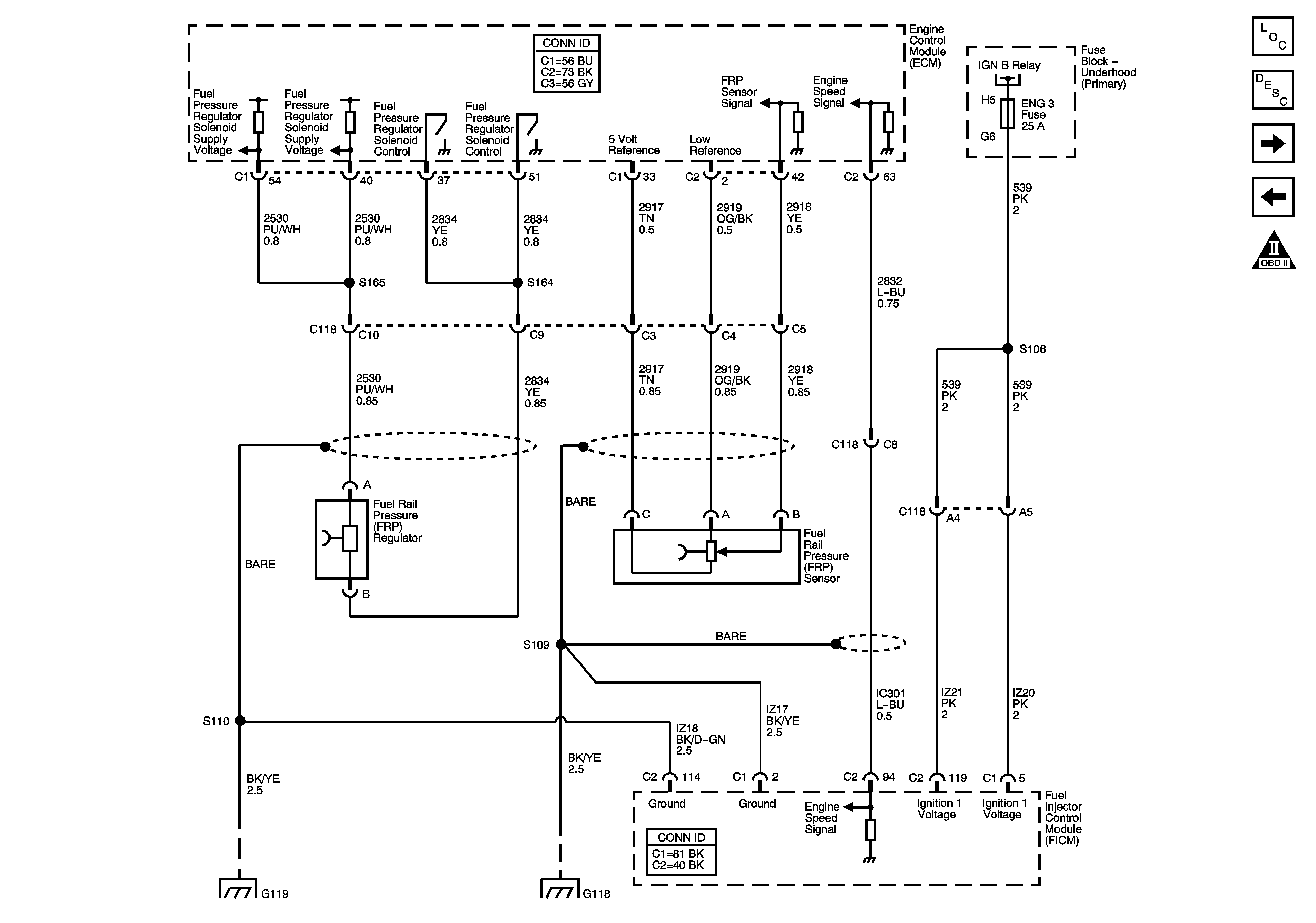

Object Number: 1405396  Size: FS
Master Electrical Component List
Exhaust Gas Recirculation (EGR) System Description
Engine Data Sensors-Glow Plug Controls
Engine Data Sensors-VSS
Engine Controls Schematic Icons
Fuse Block-Underhood Ignition A and B Relays
G118, G119, and G120
Figure 8:

Engine Data Sensors - Glow Plug Controls
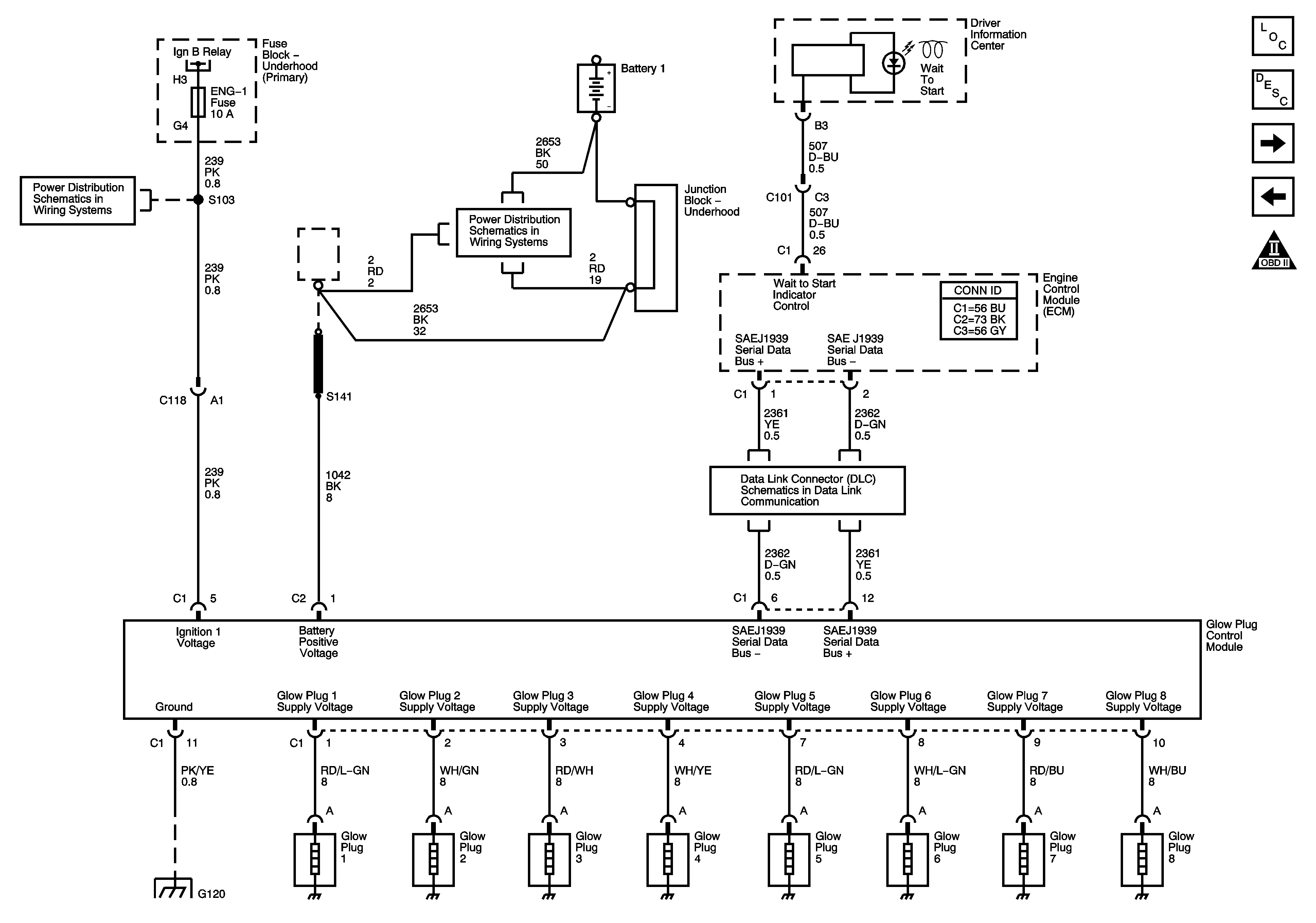

Object Number: 1405397  Size: FS
Master Electrical Component List
Exhaust Gas Recirculation (EGR) System Description
Fuel Controls-Fuel Pump Controls
Engine Data Sensors-Injection Timing Controls
Engine Controls Schematic Icons
Fuse Block-Underhood Ignition A and B Relays
B+ Bus Bar
J1939 Serial Data (L65/L18/LG4/LC8) - 2 of 2
G118, G119, and G120
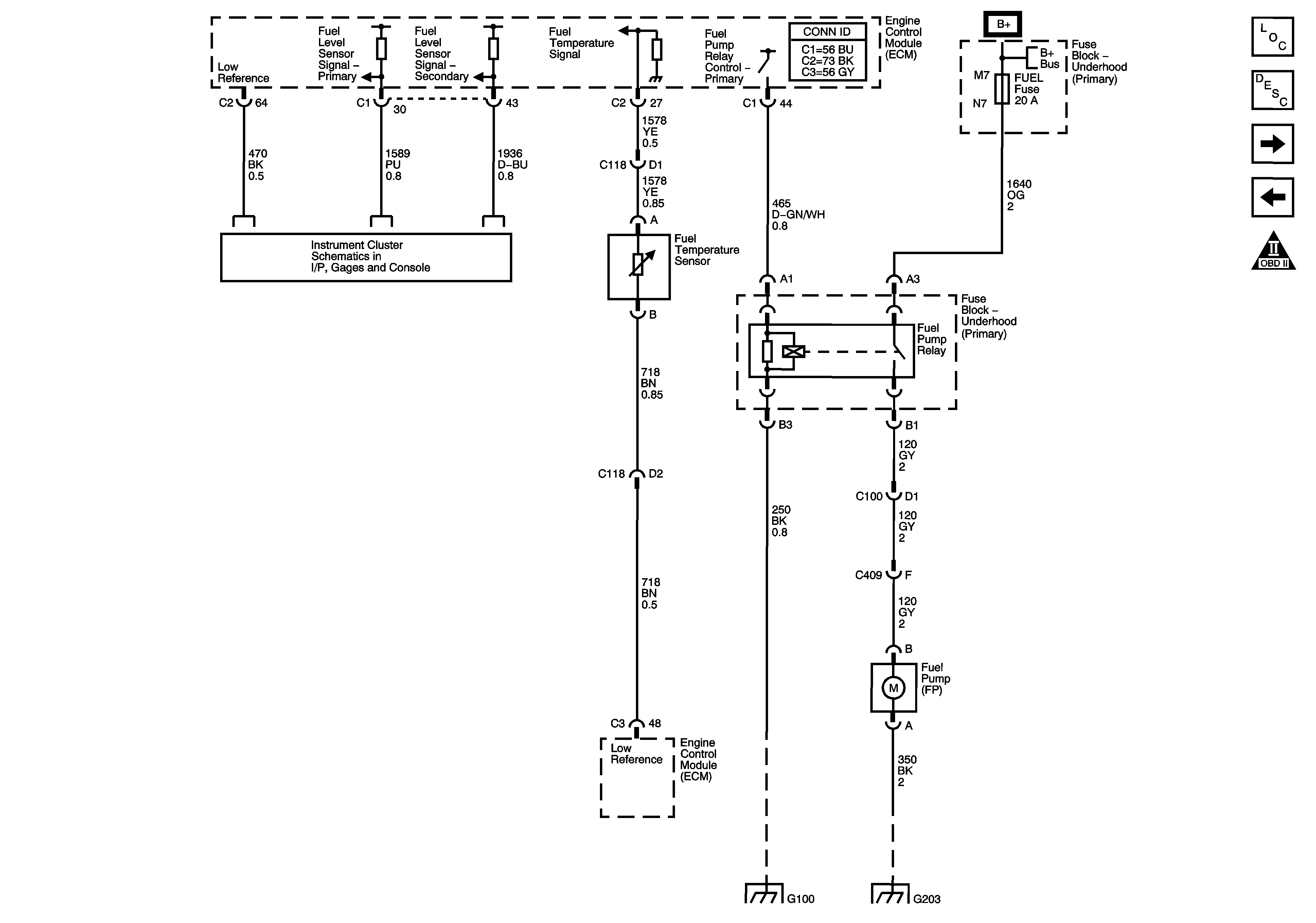
Figure 9:

Fuel Controls - Fuel Pump Controls


Object Number: 1405399  Size: FS
Master Electrical Component List
Fuel System Description
Fuel Controls-Water in Fuel/Temperature Sensors
Engine Data Sensors-Glow Plug Controls
Engine Controls Schematic Icons
Fuel Gage
B+ Bus Bar
G100 (LB7)
G112, G113, G203 - 4 of 4, G204, G205, and G400
Figure 10:

Fuel Controls - Water in Fuel/Temperature Sensors
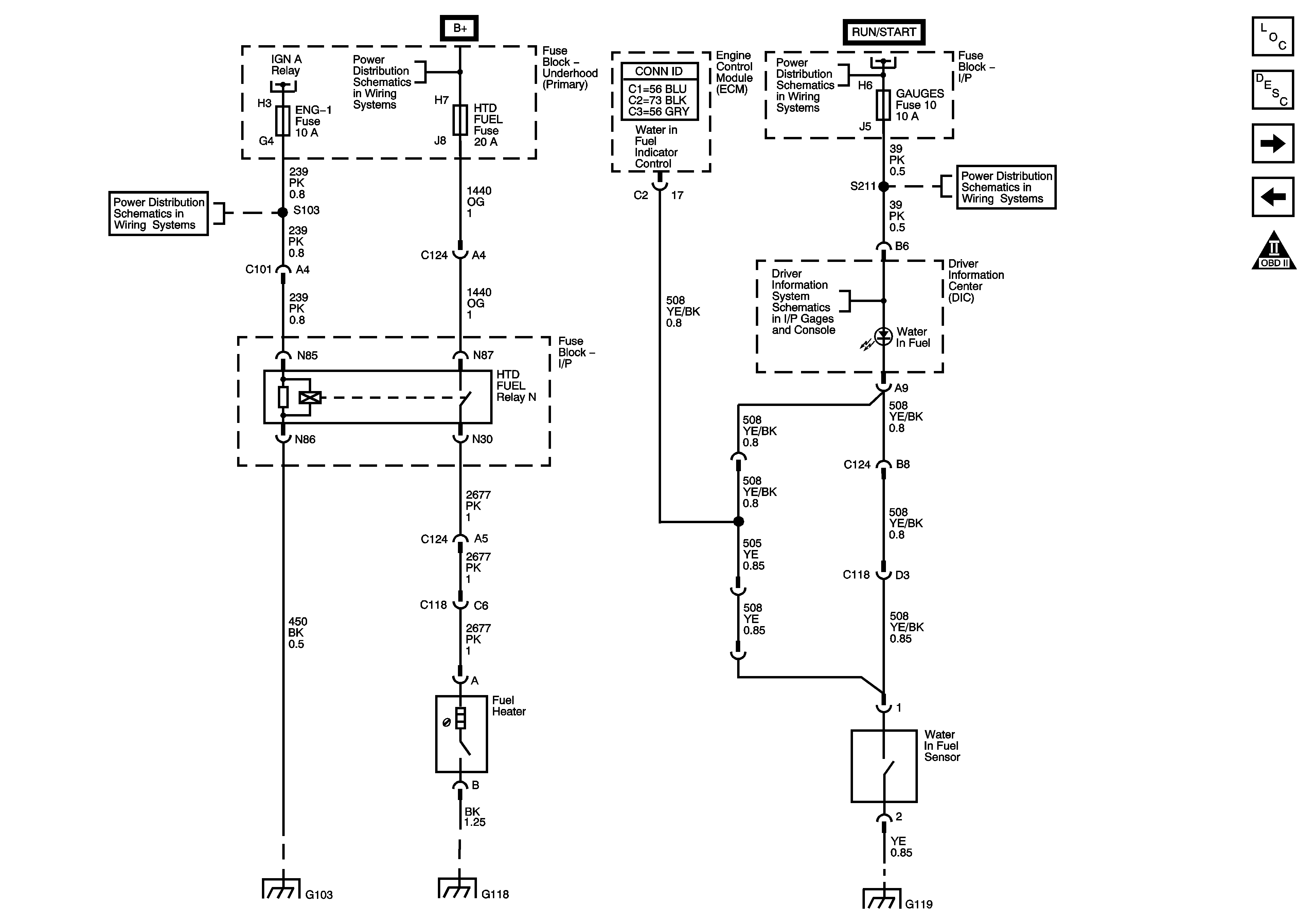

Object Number: 1405401  Size: FS
Master Electrical Component List
Fuel System Description
Fuel Controls-Fuel Injectors
Fuel Controls-Fuel Pump Controls
Engine Controls Schematic Icons
Fuse Block-Underhood Ignition A and B Relays
B+ Bus Bar
Ignition Switch - OFF/RUN/START, RUN/START and START Bus Bars
GAUGES, L-RR TRUCK, R-RR TRUCK, and SIR Fuses/Circuit Breakers
Driver Information Center (DIC)
G103 - 1 of 2, G105, and G106
G118, G119, and G120
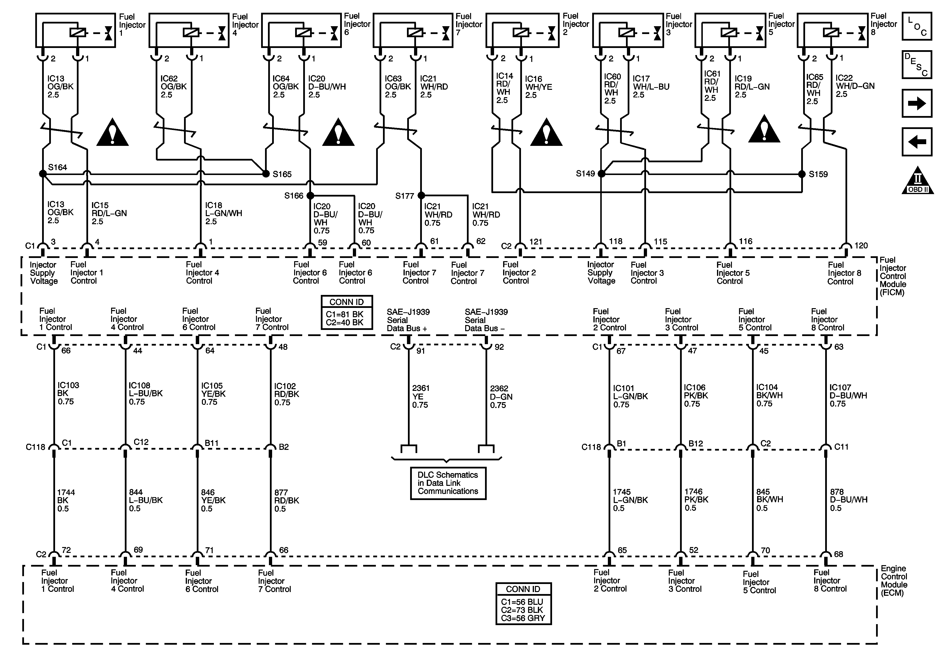
Figure 11:

Fuel Controls - Fuel Injectors


Object Number: 1405405  Size: FS
Master Electrical Component List
Fuel System Description
Controlled/Monitored Subsystem References
Fuel Controls-Water in Fuel/Temperature Sensors
Engine Controls Schematic Icons
J1939 Serial Data (L65/L18/LG4/LC8) - 2 of 2
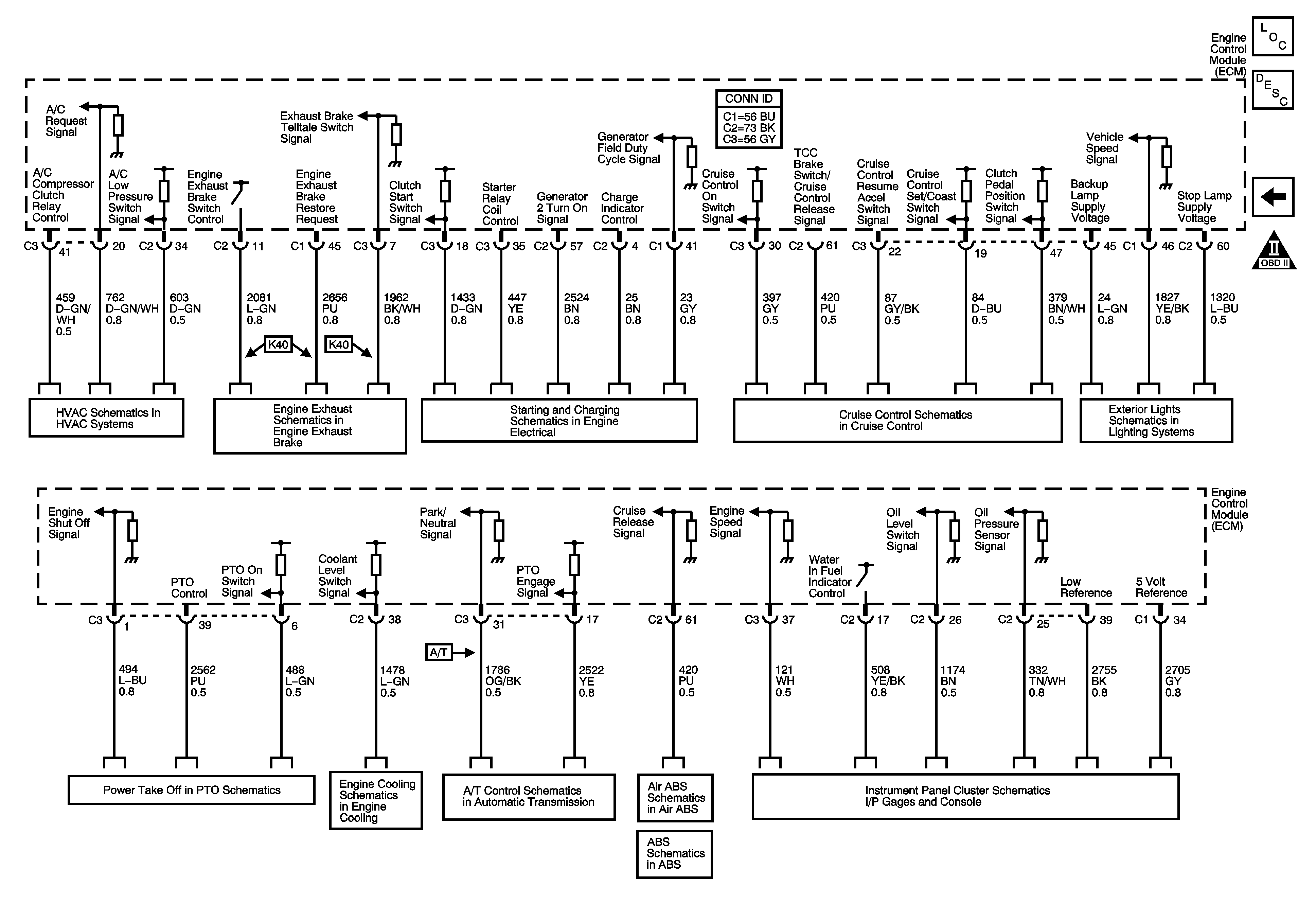
Figure 12:

Controlled/Monitored Subsystem References


Object Number: 1405412  Size: FS
Master Electrical Component List
Engine Control Module Description
Fuel Controls-Fuel Injectors
Engine Controls Schematic Icons
A/C Compressor Controls (C60)
Engine Exhaust System
Starter Control (LG4/LG5)
L18/LB7/LG4/LLY
Backup Lamps
Power Take-Off (LG5)
Electronic Fan Controls, Coolant Level Switch
Overdrive Defeat and CAN Serial Data
Traction Control and Brake Lamp Switch
Stoplamp Switch
Power and Indicators