GM Service Manual Online
For 1990-2009 cars only
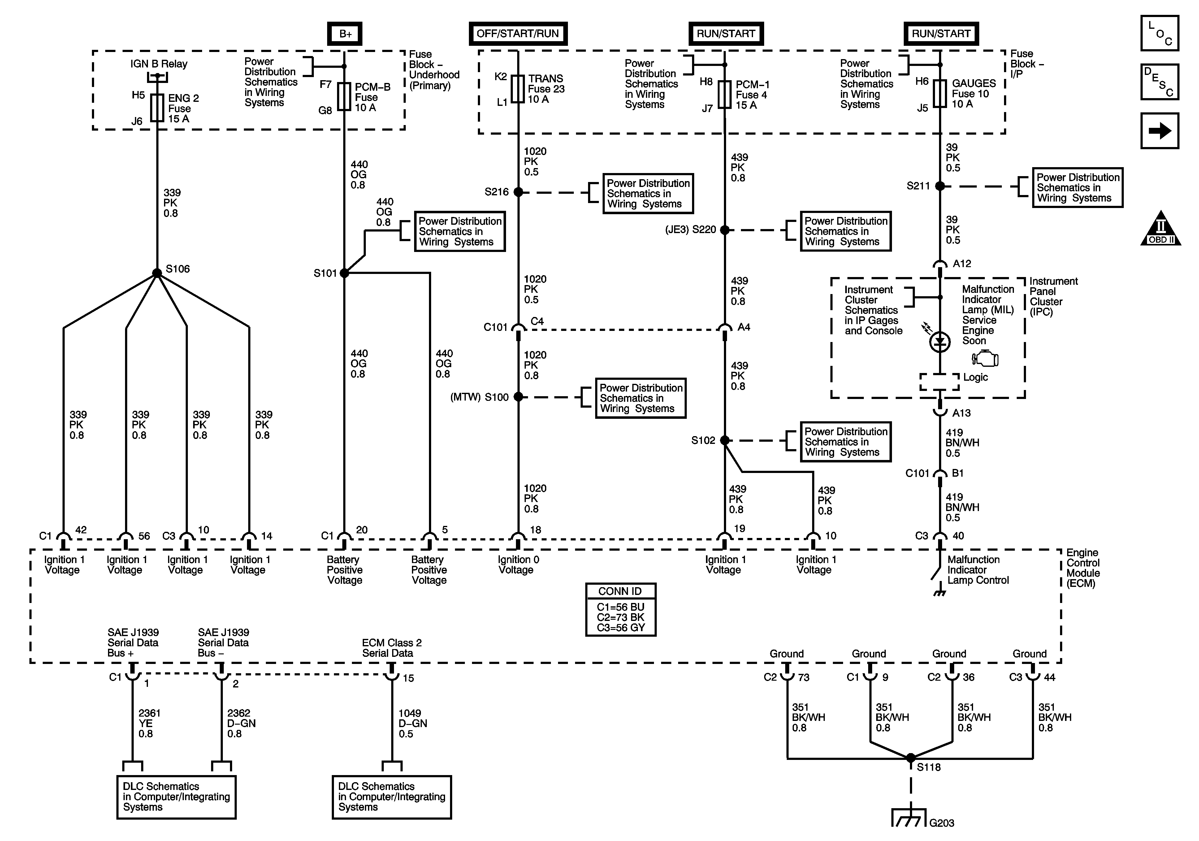
Figure 1:

Module Power, Ground, Serial Data, and MIL

Object Number: 1492843  Size: FS
Master Electrical Component List
Engine Control Module Description
Fuseblocks - Underhood Ignition A and B Relays
Engine Controls Schematic Icons
Fuseblocks - Underhood Ignition A and B Relays
B+ Bus
Ignition Switch - OFF/RUN/START, RUN/START and START Busses
A/C COMP, HTD FUEL, PCM-B, and RR DEFOG Fuses
START and TRANS Fuses/Circuit Breaker
ENGINE and PCM-1 Fuses/Circuit Breakers
GAGES, L-RR TRUCK, R-RR TRUCK, and SIR Fuses/Circuit Breakers
Instrument Panel Cluster - 1 of 2
START and TRANS Fuses/Circuit Breaker
ENGINE and PCM-1 Fuses/Circuit Breakers
J1939 Serial Data - LLY
Splice Pack SP203
G203 - 2 of 4
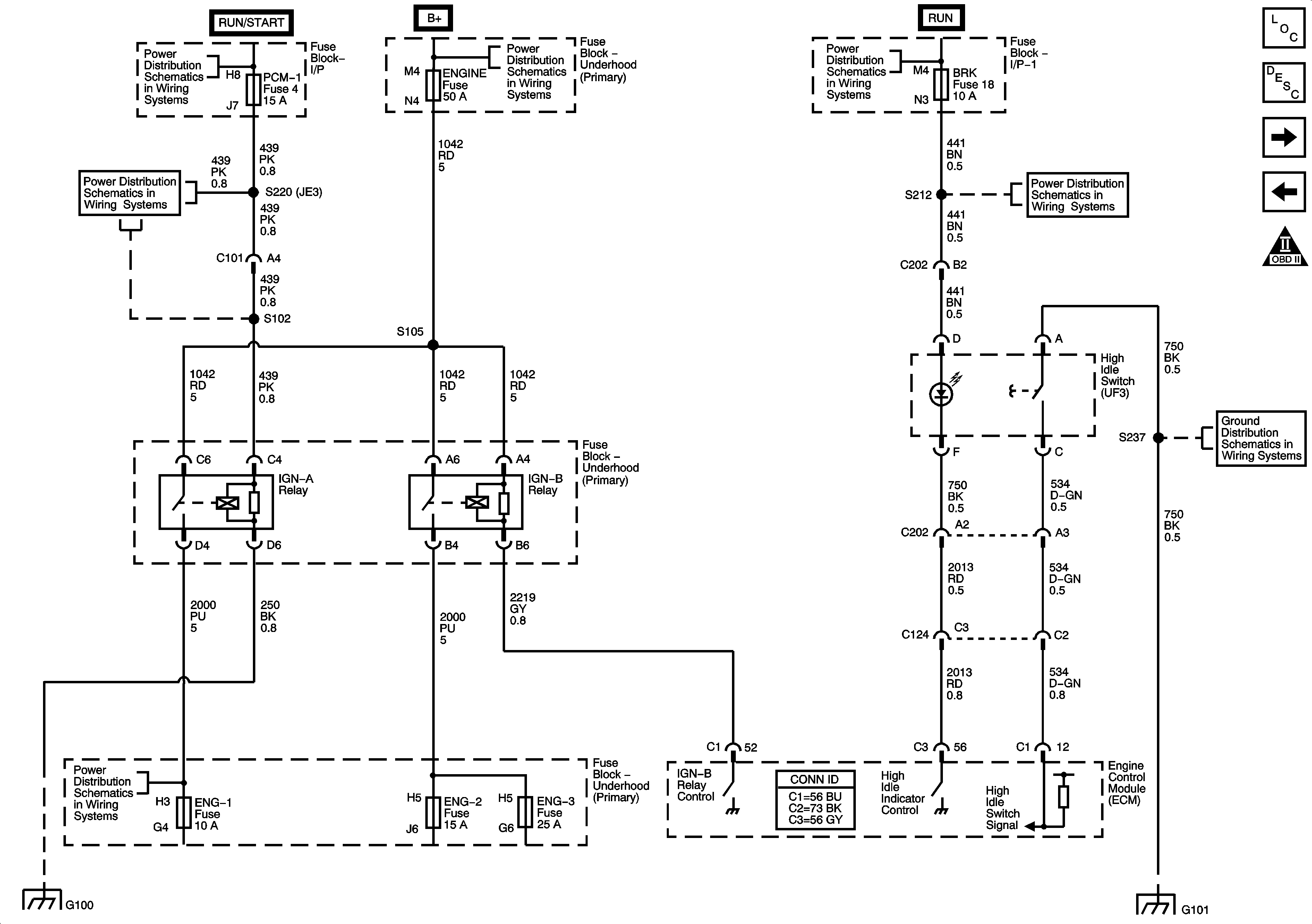
Figure 2:

Fuse Block - Underhood, Ignition A and B Relays

Object Number: 1492844  Size: FS
Master Electrical Component List
Engine Control Module Description
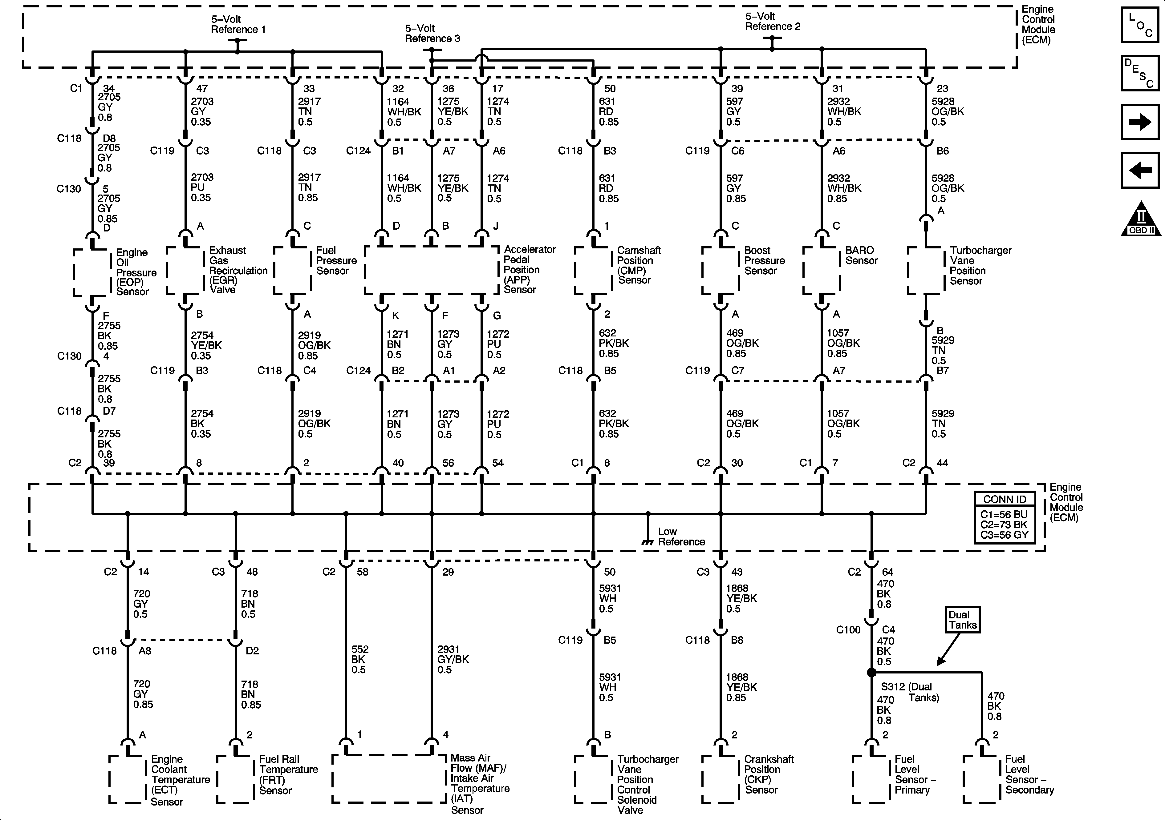
Engine Data Sensors - 5-Volt and Low Reference
Module Power, Ground, Serial Data and MIL
Engine Controls Schematic Icons
Ignition Switch - OFF/RUN/START, RUN/START and START Busses
B+ Bus
Ignition Switch - RUN and ACC/RUN Busses
ENGINE and PCM-1 Fuses/Circuit Breakers
AXLE/4WD, BRAKE, CHASSIS, and HTR/AC Fuses/Circuit Breakers
G101 - 1 of 2
ENG-1 and ENG-4 Fuses - L18/LLY
G100 - LLY
G101 - 1 of 2
Figure 3:

Engine Data Sensors - 5-Volt and Low Reference


Object Number: 1492846  Size: FS
Master Electrical Component List
Engine Control Module Description
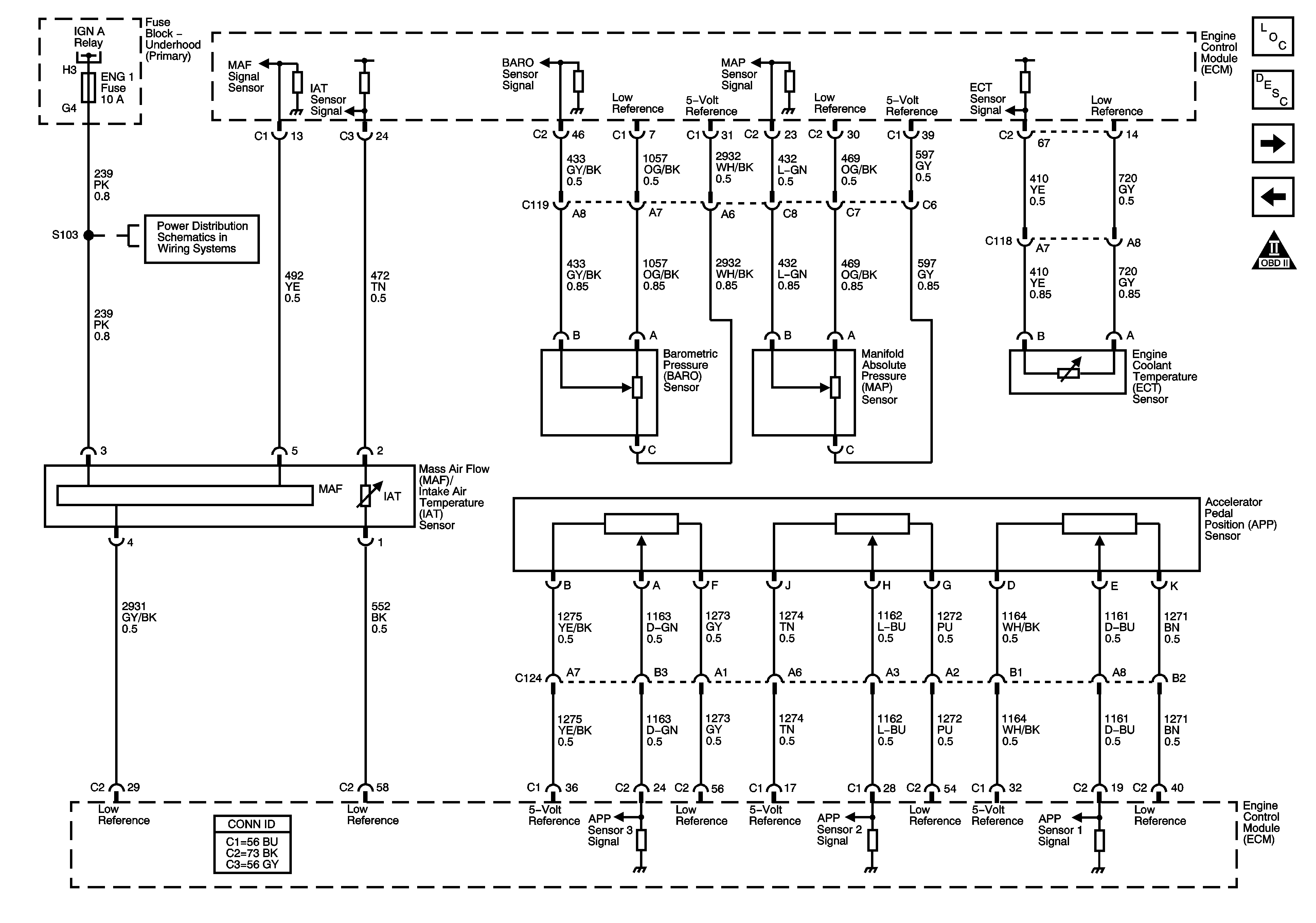
Engine Data Sensors - Pressure and Temperature
Fuseblocks - Underhood Ignition A and B Relays
Engine Controls Schematic Icons
Figure 4:

Engine Data Sensors - Pressure and Temperature


Object Number: 1492847  Size: FS
Master Electrical Component List
Accelerator Pedal Position System Description
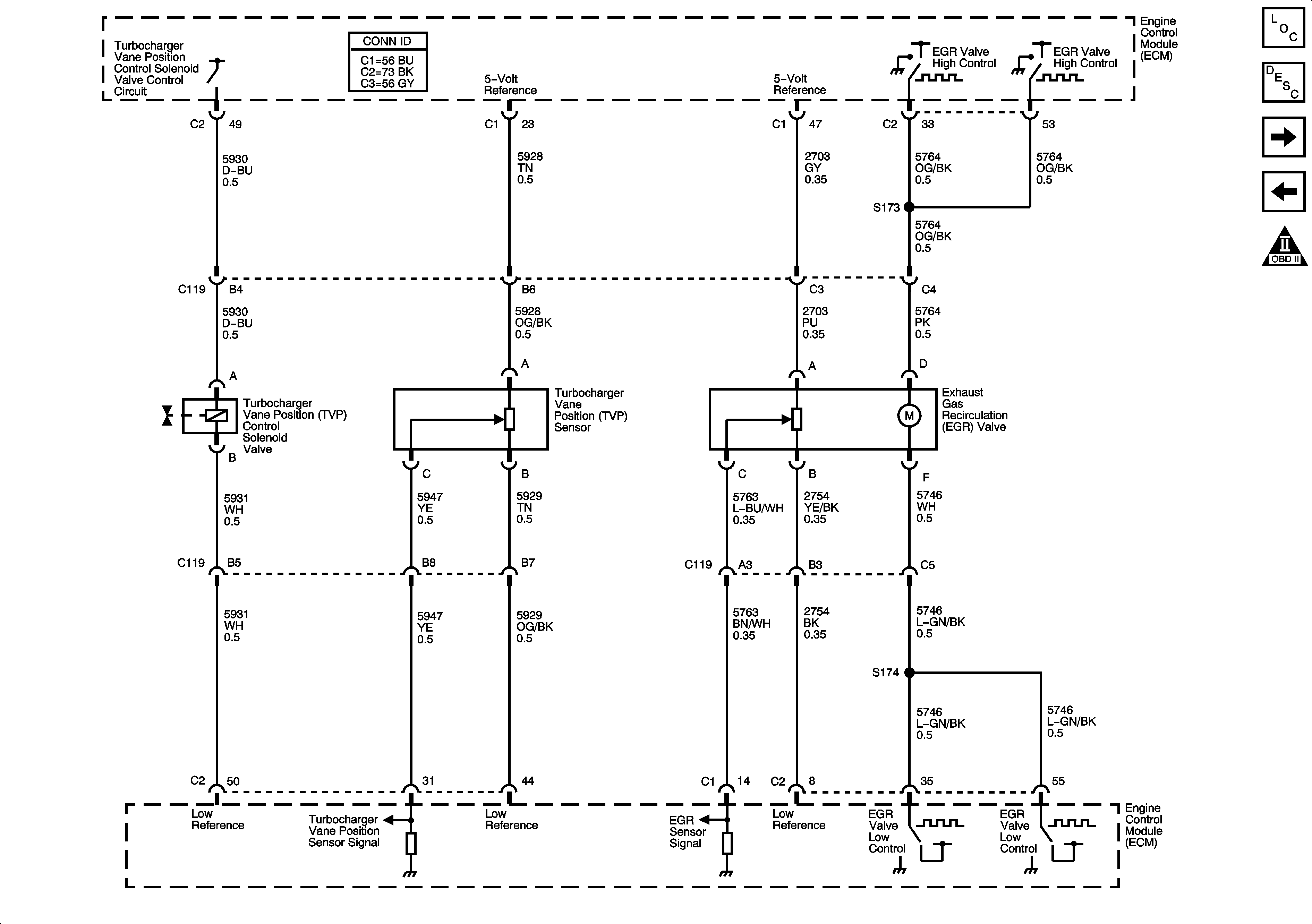
Engine Data Sensors - EGR and Turgocharger
Engine Data Sensors - 5-Volt and Low Reference
Engine Controls Schematic Icons
Fuseblocks - Underhood Ignition A and B Relays
ENG-1 and ENG-4 Fuses - L18/LLY
Figure 5:

Engine Data Sensors - Turbocharger and EGR

Object Number: 1492849  Size: FS
Master Electrical Component List
Turbocharger System Description
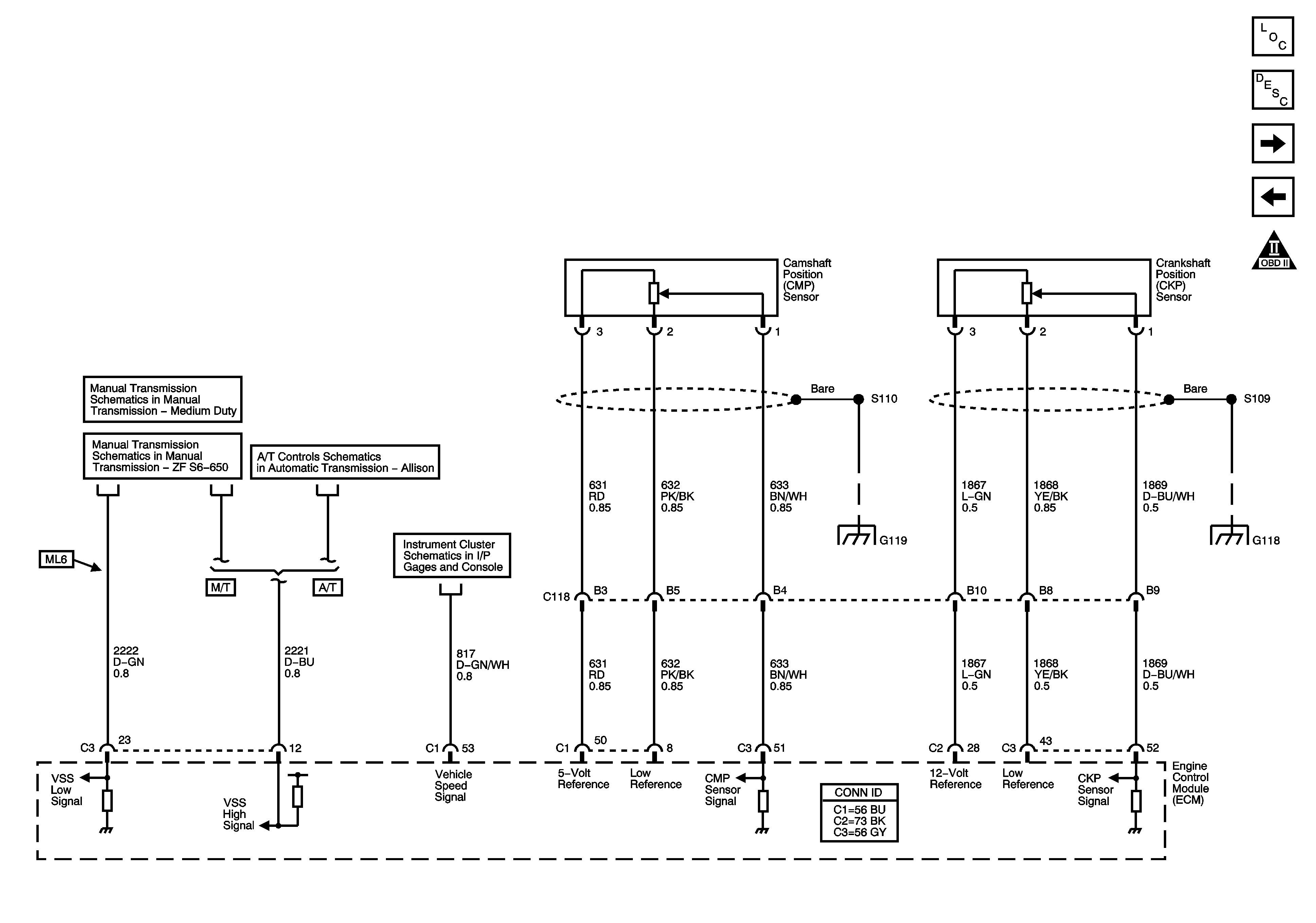
Engine Data Sensors - VSS and Ignition Timing Controls
Engine Data Sensors - Pressure and Temperature
Engine Controls Schematic Icons
Figure 6:

Engine Data Sensors - VSS and Ignition Timing Controls


Object Number: 1492851  Size: FS
Master Electrical Component List
Engine Control Module Description
Engine Date Sensors - Injection Timing Controls
Engine Data Sensors - EGR and Turgocharger
Engine Controls Schematic Icons
Manual Transmission Schematics
Module Power, Ground, Serial Data, and MIL, VSS, and Torque
Instrument Panel Cluster - 2 of 2
G118, G119, and G120
Figure 7:

Engine Data Sensors - Injection Timing Controls
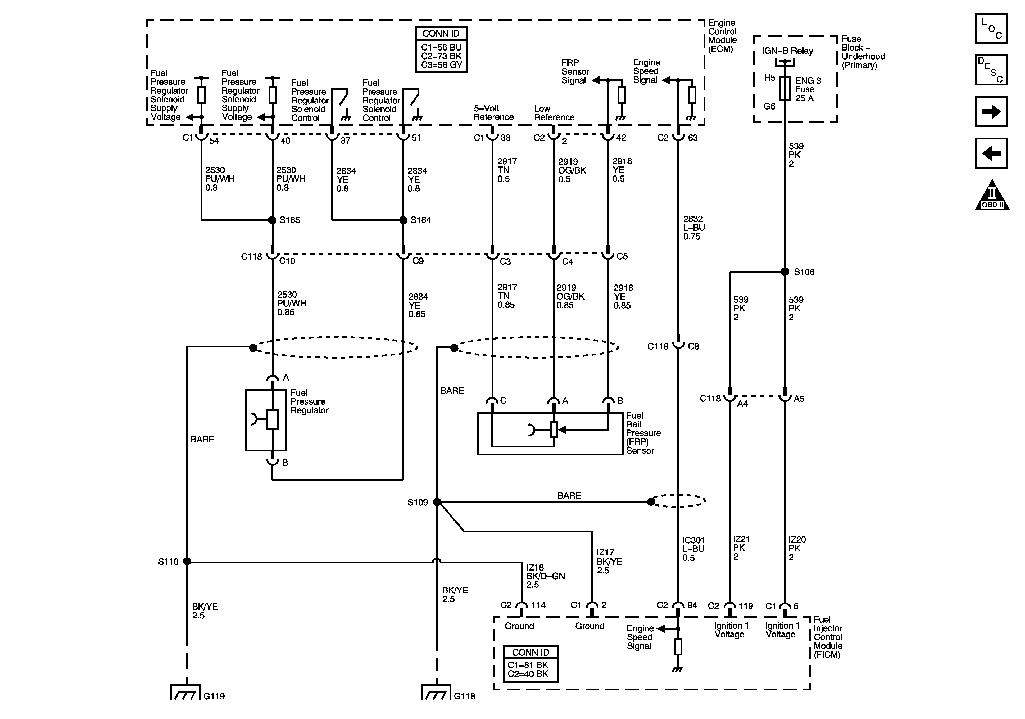

Object Number: 1565712  Size: FS
Master Electrical Component List
Fuel System Description
Engine Data Sensors - Glow Plug Controls
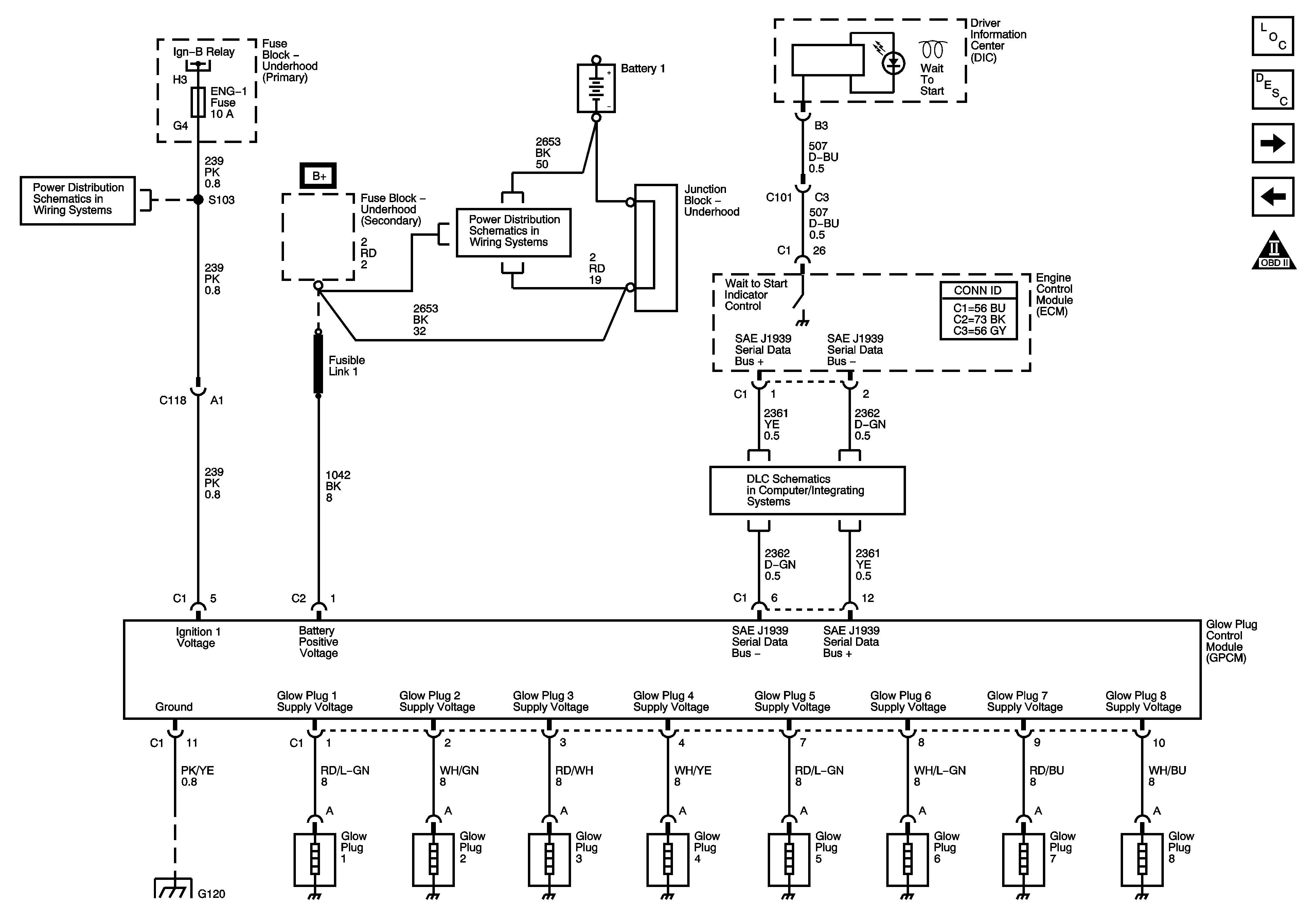
Engine Data Sensors - VSS and Ignition Timing Controls
Engine Controls Schematic Icons
Fuseblocks - Underhood Ignition A and B Relays
G118, G119, and G120
Figure 8:

Engine Data Sensors - Glow Plug Controls


Object Number: 1492854  Size: FS
Master Electrical Component List
Glow Plug System Description
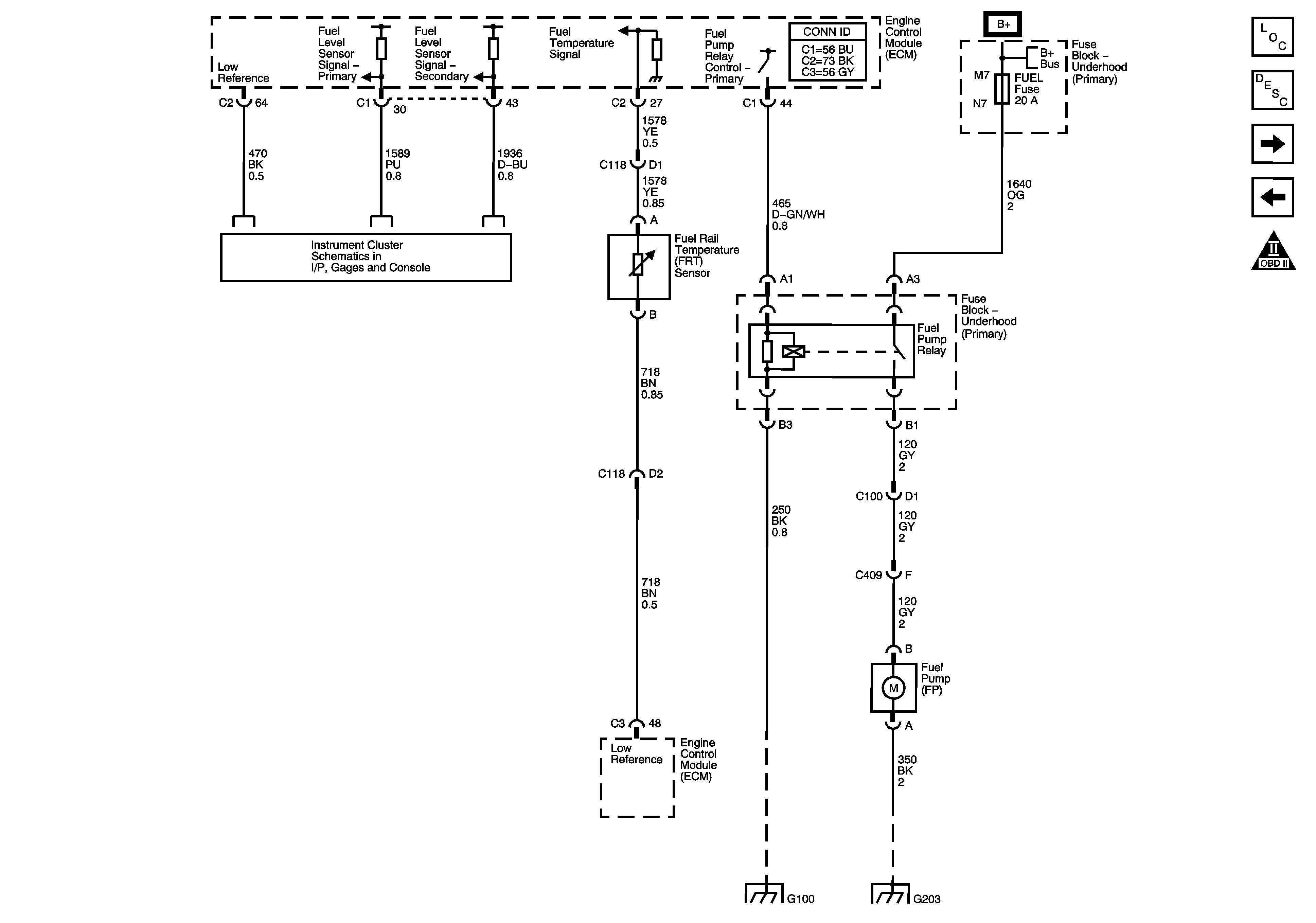
Fuel Controls - Fuel Pump Controls
Engine Date Sensors - Injection Timing Controls
Engine Controls Schematic Icons
Fuseblocks - Underhood Ignition A and B Relays
ENG-1 and ENG-4 Fuses - L18/LLY
B+ Bus
J1939 Serial Data - LLY
G118, G119, and G120
Figure 9:

Fuel Controls - Fuel Pump Controls


Object Number: 1492859  Size: FS
Master Electrical Component List
Fuel System Description
Fuel Controls - Water-In-Fuel/Temperature Sensors
Engine Data Sensors - Glow Plug Controls
Engine Controls Schematic Icons
FUEL Fuse/Circuit Breaker - L18/LLY, PCV Circuit Breaker - LG4, and ECM-B Circuit Breaker - LG5
G100 - LLY
G112, G113, G203 - 4 of 4, G204, G205, and G400
Figure 10:

Fuel Controls - Water in Fuel/Temperature Sensors
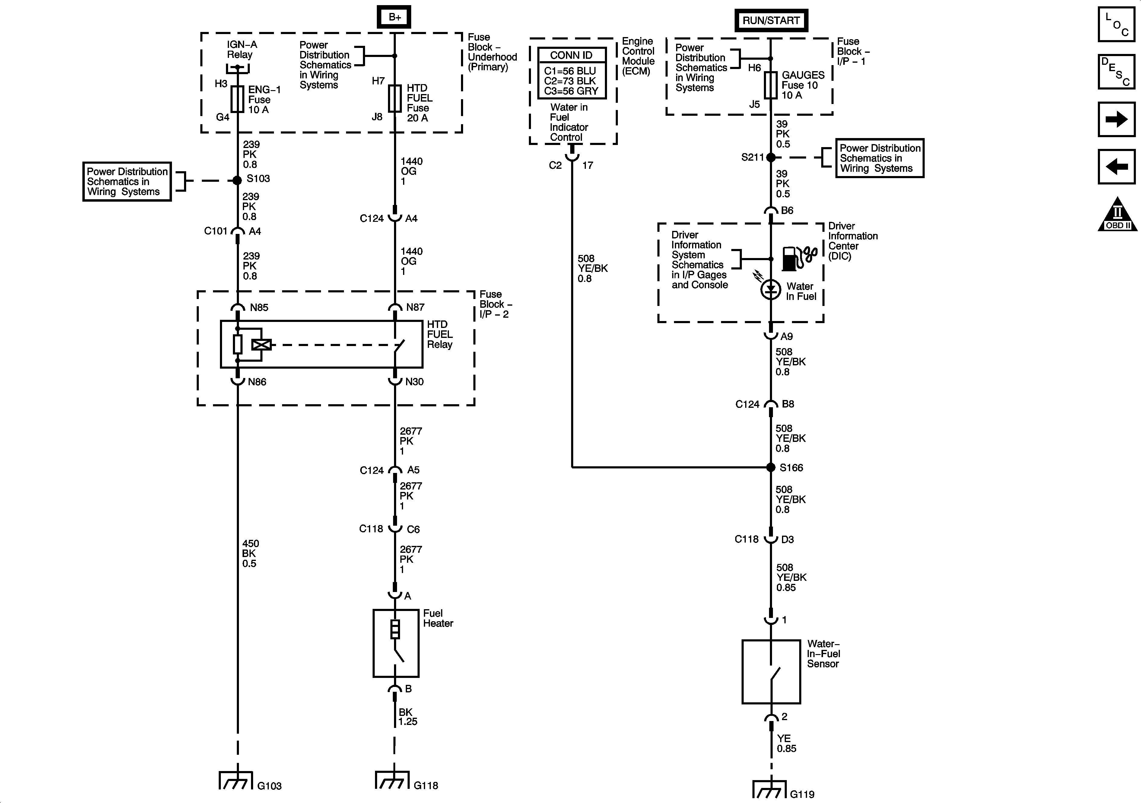

Object Number: 1492860  Size: FS
Master Electrical Component List
Fuel System Description
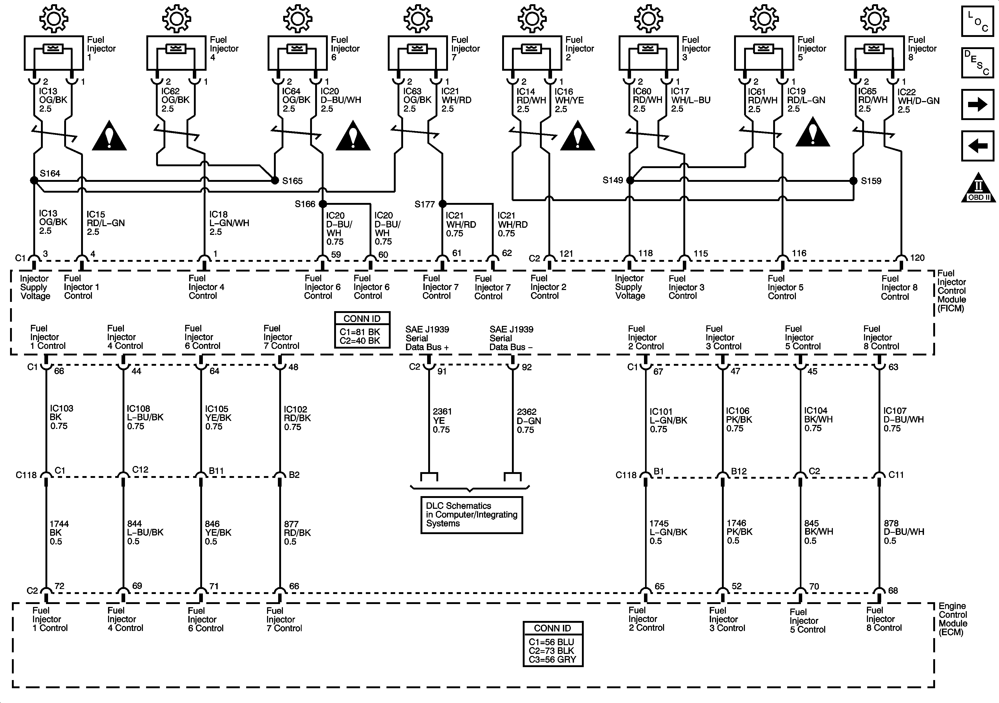
Fuel Controls - Fuel Injectors
Fuel Controls - Fuel Pump Controls
Engine Controls Schematic Icons
Fuseblocks - Underhood Ignition A and B Relays
B+ Bus
Ignition Switch - OFF/RUN/START, RUN/START and START Busses
ENG-1 and ENG-4 Fuses - L18/LLY
GAGES, L-RR TRUCK, R-RR TRUCK, and SIR Fuses/Circuit Breakers
DIC
G103 - 1 of 2, G105, and G106
G118, G119, and G120
Figure 11:

Fuel Controls - Fuel Injectors


Object Number: 1492861  Size: FS
Master Electrical Component List
Fuel System Description
Controlled/Monitored Subsystem References
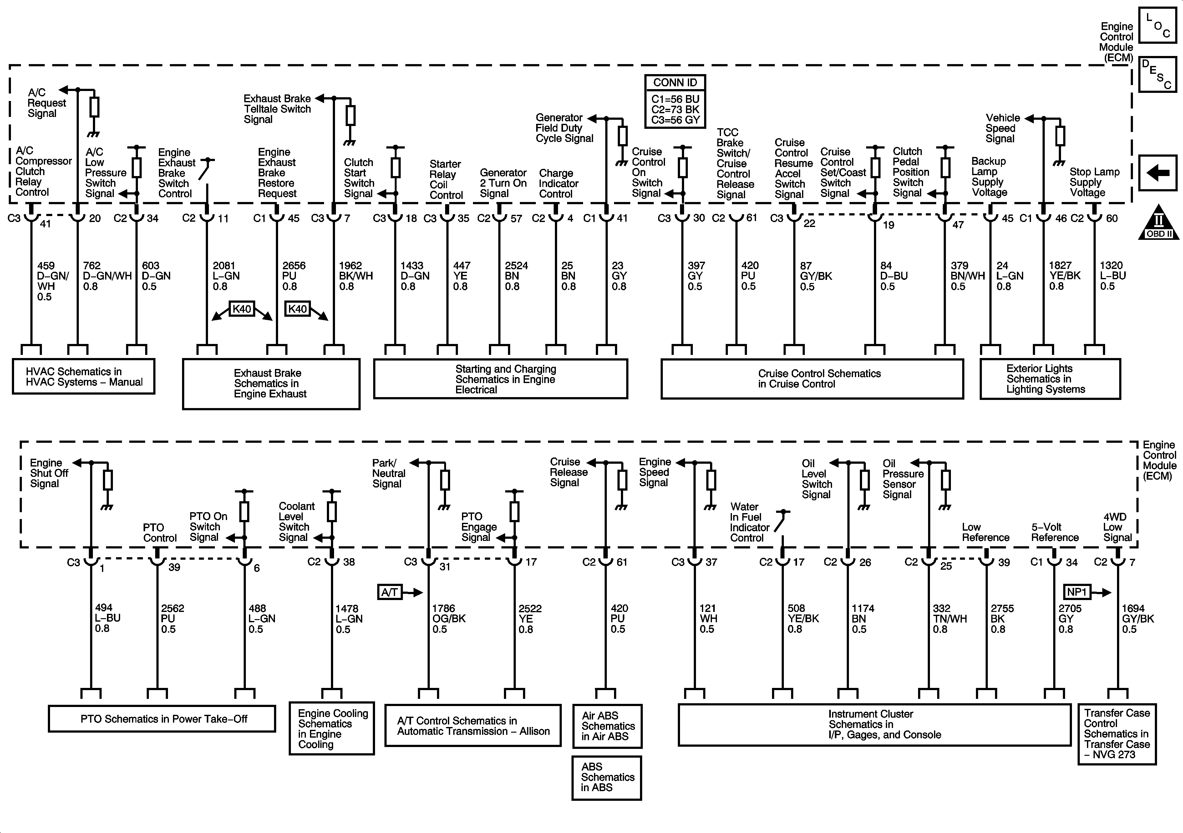
Fuel Controls - Water-In-Fuel/Temperature Sensors
Engine Controls Schematic Icons
J1939 Serial Data - LLY
Figure 12:

Controlled/Monitored Subsystem References


Object Number: 1492862  Size: FS
Master Electrical Component List
Engine Control Module Description
Fuel Controls - Fuel Injectors
Engine Controls Schematic Icons
Blower Controls (C60)
Engine Exhaust Brake Schematics
Starting System (L18/LLY)
Charging System (L18/LLY)
Cruise Control Schematics
Backup Lamps and Backup Alarm - UZF
C305 - Upfitter Lighting Connector
Stop Lamp Switch
1 of 2
Engine Cooling Schematics
PNP Switch and Cxxx (TRANS OPT Connector)
Stop Lamp Switch
Traction Control and Brake Lamp Switch
Instrument Panel Cluster - 2 of 2
Power, Ground, Class 2 Serial Data, Transfer Case Shift Control Module and Transfer Case Encoder Motor