Air Brake Automatic Slack Adjuster Replacement Arvin-Meritor
Removal Procedure
- Block the wheels.
- Cage the rear air brake chambers. Refer to Caging the Rear Air Brake Chamber .
- Drain all air reservoirs. Refer to Air Brake Reservoir Draining .
- Raise and support the vehicle with safety stands. Refer to Lifting and Jacking the Vehicle .
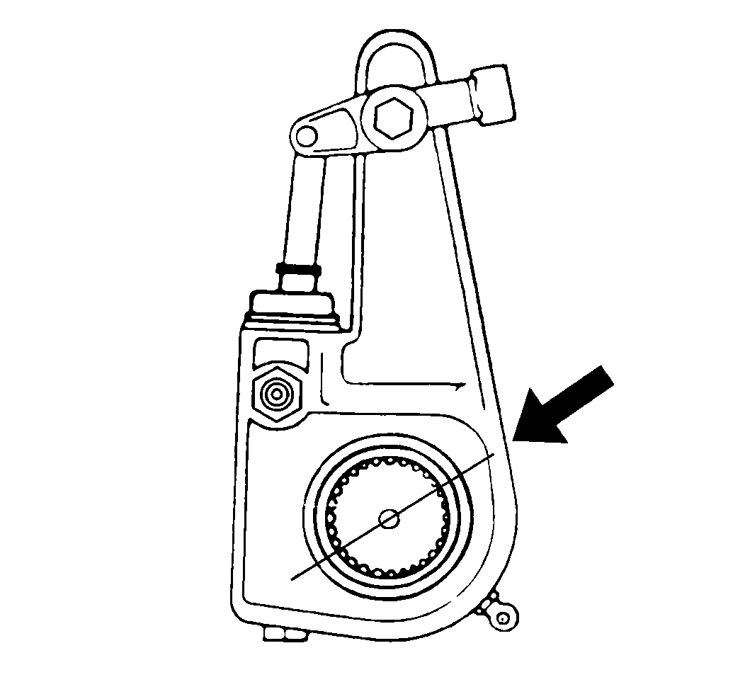
- Mark the position of the air brake automatic slack adjuster to the camshaft by drawing a straight line on both parts.
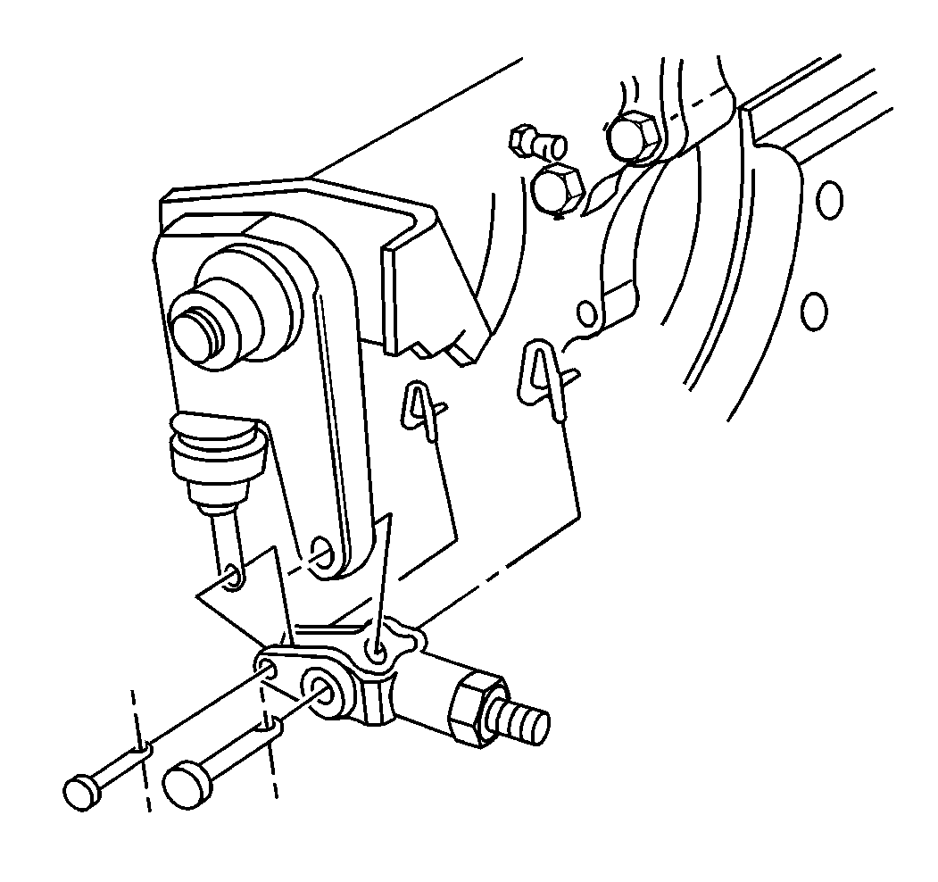
- Remove the retainers.
- Remove the air brake chamber clevis pins.
- Fully release the air brake automatic slack adjuster using the following steps:
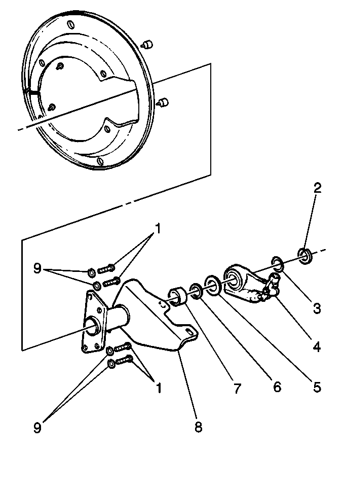
- Remove the camshaft snap ring.
- Remove the camshaft washer(s) (9).
- Remove the air brake automatic slack adjuster (4).
- Check the air brake automatic slack adjuster adjusting nut torque using the following steps:
- Inspect the air brake chamber clevis pins for wear or damage.
- Measure the bushing in the arm of the air brake automatic slack adjuster (4).
Important: For unit repair information on the Arvin-Meritor® air brake automatic slack adjuster contact the Field Support Center at 1-800-535-5560.
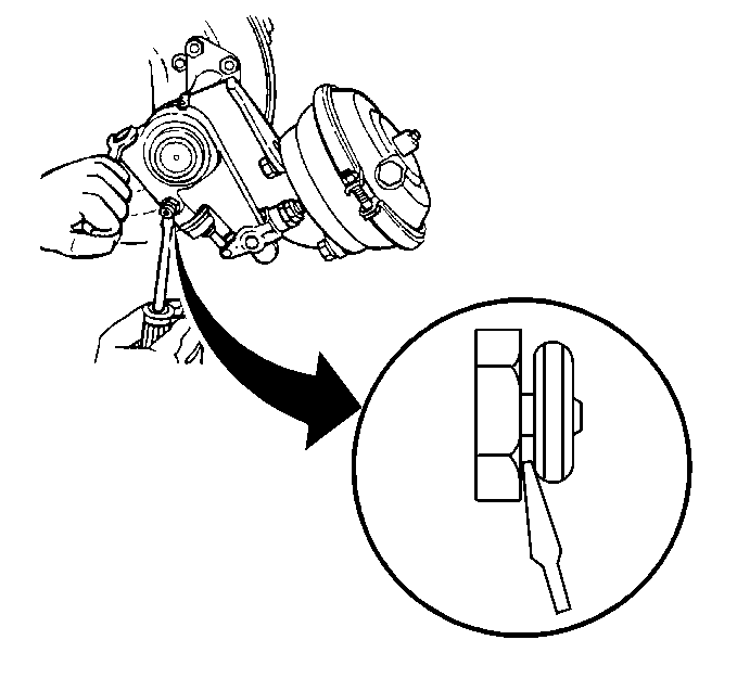
| 8.1. | Disengage the pawl with a screwdriver. |
| 8.2. | Turn the air brake automatic slack adjuster adjusting nut until the air brake automatic slack adjuster is free from the air brake chamber clevis. |
| 8.3. | Release the pawl so that the pawl snaps into engagement. |
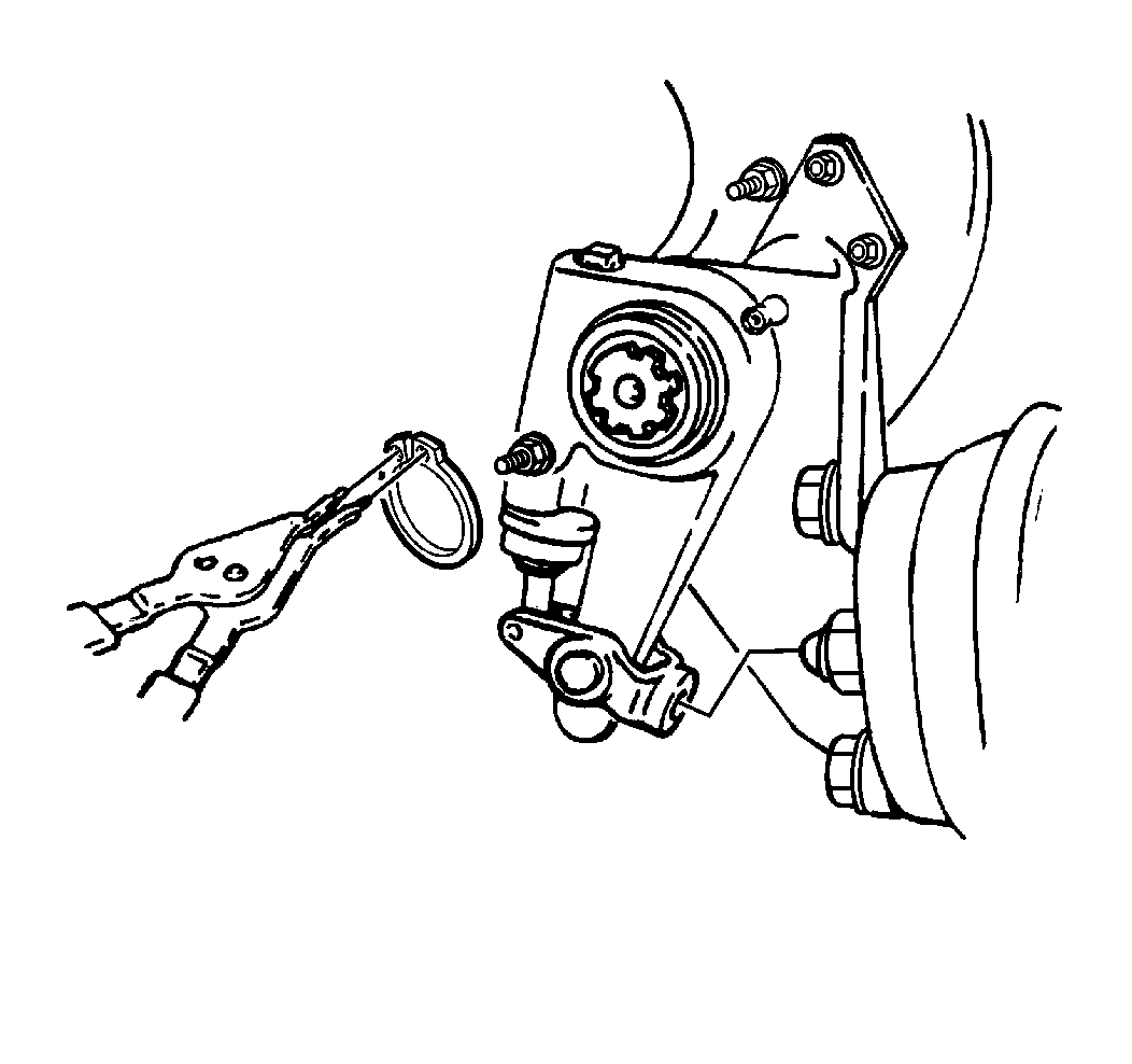
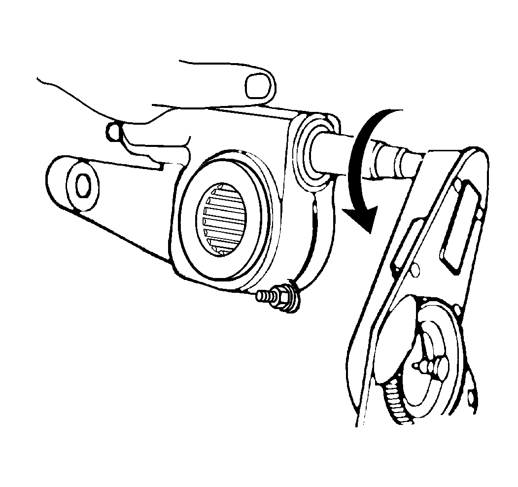
| 12.1. | Use a pound/inch torque wrench in order to rotate the air brake automatic slack adjuster adjusting nut counterclockwise. |
| 12.2. | Turn the air brake automatic slack adjuster gear 360 degrees, 22 rotations of the air brake automatic slack adjuster adjusting nut. The torque must remain less than 4.5 N·m (40 lb in). Replace the air brake automatic slack adjuster if the torque specification is exceeded. |

Replace the air brake chamber clevis pins if necessary.

Replace the bushings if the diameter exceeds 13.5 mm (0.531 in).
Installation Procedure
- Install the air brake automatic slack adjuster to the camshaft (12).
- Install the camshaft washers (13).
- Install the camshaft snap ring.
- Disengage the pawl assembly with a screwdriver.
- Turn the slack adjuster adjusting nut until the slack adjuster arm is properly aligned with the holes in the clevis.
- Release the pawl so that the pawl snaps into engagement.
- Align the marks made on the air brake automatic slack adjuster and the camshaft.
- Fully release the air brake automatic slack adjuster.
- Install the air brake chamber clevis pins.
- Install the NEW retainers.
- Adjust the brakes. Refer to Air Drum Brake Adjustment .
- Remove the safety stands and lower the vehicle. Refer to Lifting and Jacking the Vehicle .
- Uncage the rear air brake chambers. Refer to Caging the Rear Air Brake Chamber .
- Check for proper brake operation.
- Apply the parking brake.
- Remove the wheel blocks.



Air Brake Automatic Slack Adjuster Replacement Eaton
Removal Procedure
- Block the wheels.
- Cage the rear air brake chambers. Refer to Caging the Rear Air Brake Chamber .
- Drain all air reservoirs. Refer to Air Brake Reservoir Draining .
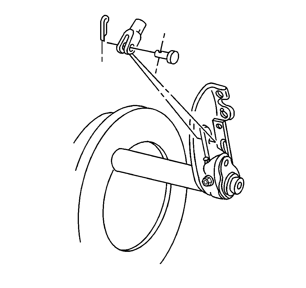
- Remove the retainer.
- Remove the air brake chamber clevis pin cotter pin.
- Remove the air brake chamber clevis pin.
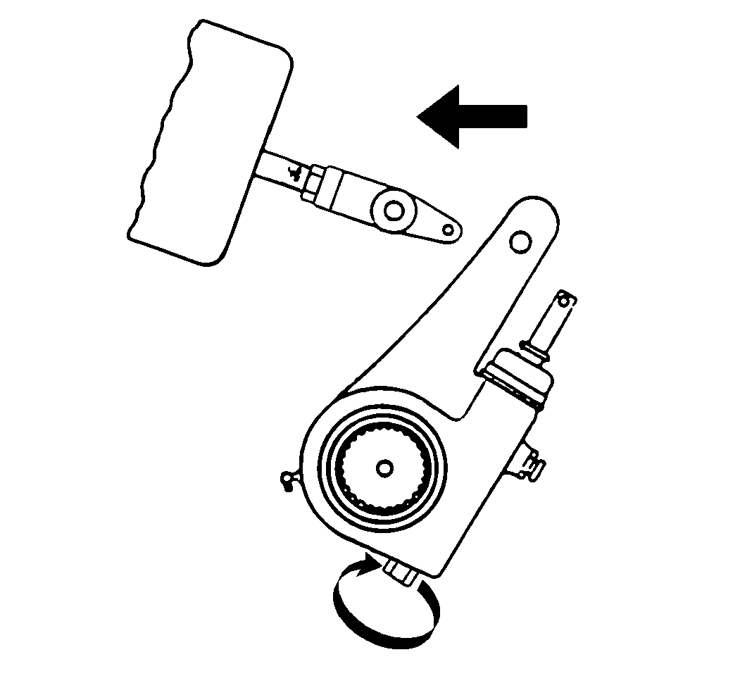
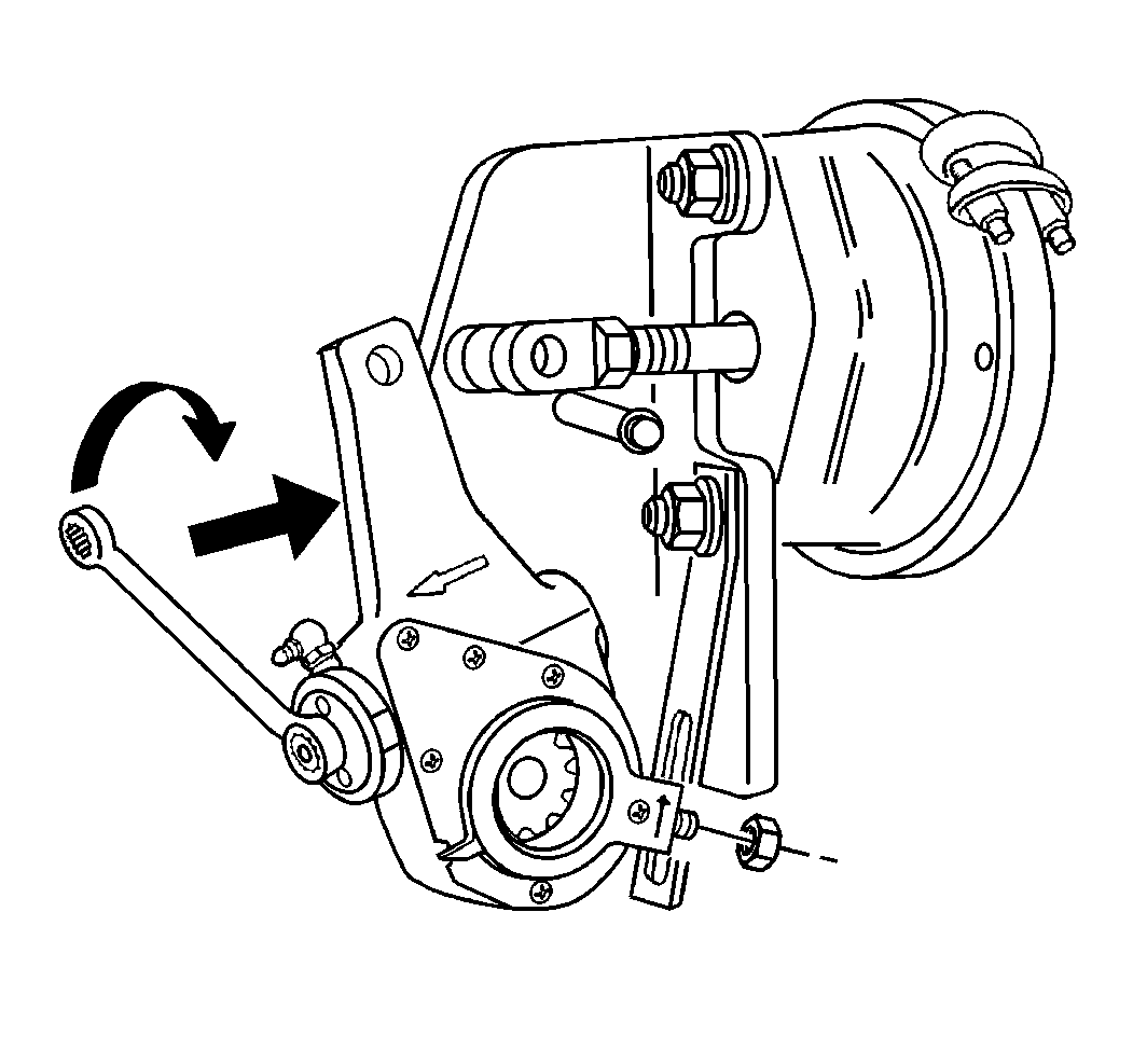
- Fully release the slack adjuster by turning the slack adjuster counterclockwise until the slack adjuster arm is free from the clevis.
- Remove the air brake automatic slack adjuster control arm nut and the washer.
- Remove the camshaft snap ring.
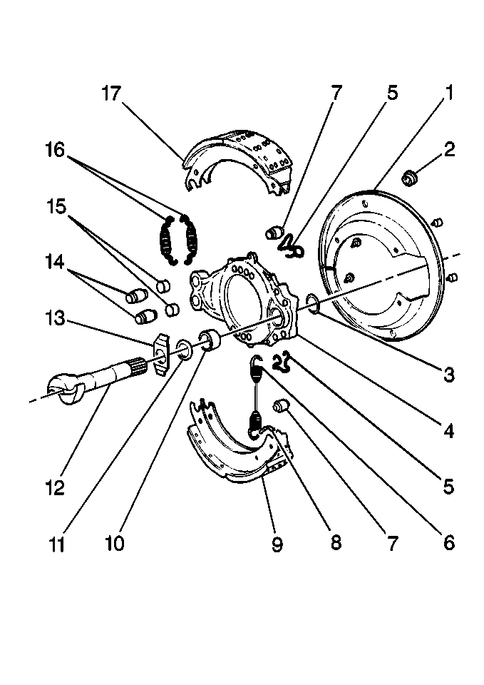
- Remove the camshaft washer(s) (5).
- Remove the air brake automatic slack adjuster (4).
- Inspect the air brake automatic slack adjuster (4) for damage or excessive wear.
Important: Service the Eaton® air brake automatic slack adjuster by replacement only.
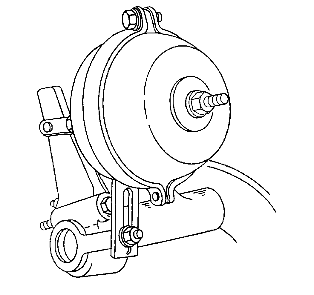
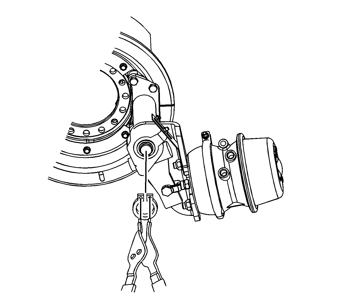

Replace the air brake automatic slack adjuster (4) if damage or excessive wear is present.
Installation Procedure
- Lubricate the camshaft splines. Use the Anti-Seize Lubricant GM P/N 1052771, (Canadian P/N 993128) or equivalent.
- Install the air brake automatic slack adjuster (4) to the camshaft.
- Install the camshaft washers (5).
- Install the camshaft snap ring.
- Loosely install the air brake automatic slack adjuster control arm washer.
- Loosely install the air brake automatic slack adjuster control arm nut.
- On Eaton® Automatic Slack Adjusters rotate the air brake automatic slack adjuster adjusting hex hue clockwise until the air brake automatic slack adjuster arm hole aligns with the air brake chamber clevis hole.
- Install the air brake chamber clevis pin.
- Remove the air brake chamber clevis pin later in order to check installation.
- Adjust the slack adjuster control arm by rotating the arm counterclockwise.
- Tighten the slack adjuster control arm nut.
- Adjust the brakes. Refer to Air Drum Brake Adjustment .
- Start the engine.
- Charge the system to the air compressor governor valve cut-out point.
- Stop the engine.
- Inspect the slack adjuster for the proper installation.
- Verify that the installation indicator is within the slot.
- Remove the air brake chamber clevis pin.
- Align the air brake chamber clevis hole and the air brake automatic slack adjuster arm hole.
- Repeat steps 7 through 17 if the air brake chamber clevis retracts towards the air brake chamber when you remove the air brake chamber clevis pin.
- Install the air brake chamber clevis pin.
- Install the air brake chamber clevis pin cotter pin.
- Check the air brake automatic slack adjuster adjusting hex torque.
- Use a pound/inch torque wrench in order to rotate the air brake automatic slack adjuster adjusting hex counterclockwise.
- A minimum of 18 N·m (13 lb ft) is necessary to overcome the clutch.
- Start the engine.
- Charge the system to the air compressor governor valve cut-out point.
- Stop the engine.
- Uncage the rear air brake chambers. Refer to Caging the Rear Air Brake Chamber .
- Check for the proper brake operation.
- Apply the parking brake.
- Remove the wheel blocks.


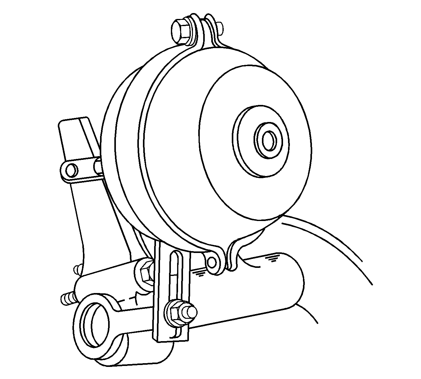

Do not install the retainer at this time.
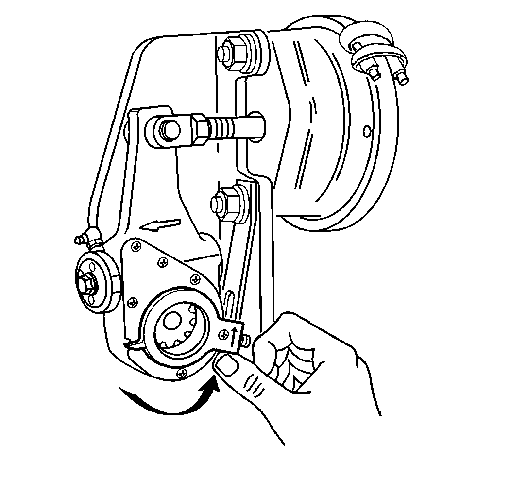
Notice: Excessive positioning force may damage the air brake automatic slack adjuster control arm. Most adjusters will be equipped with an installation indicator. The indicator must fall within the slot for proper installation. Incorrect air brake automatic slack adjuster control arm position can cause tight or dragging brakes.
Rotate away from the slack adjuster adjusting hex and towards the air brake chamber. Continue rotating until the air brake control arm comes to a definite internal stop. If necessary, use a plastic mallet in order to tap the slack adjuster control arm into position.

Notice: Use the correct fastener in the correct location. Replacement fasteners must be the correct part number for that application. Fasteners requiring replacement or fasteners requiring the use of thread locking compound or sealant are identified in the service procedure. Do not use paints, lubricants, or corrosion inhibitors on fasteners or fastener joint surfaces unless specified. These coatings affect fastener torque and joint clamping force and may damage the fastener. Use the correct tightening sequence and specifications when installing fasteners in order to avoid damage to parts and systems.
Important: Ensure that the air brake automatic slack adjuster control arm does not move from the correct position while tightening the air brake automatic slack adjuster control arm nut.
Tighten
Tighten the slack adjuster control arm nut to 17 N·m (13 lb ft).

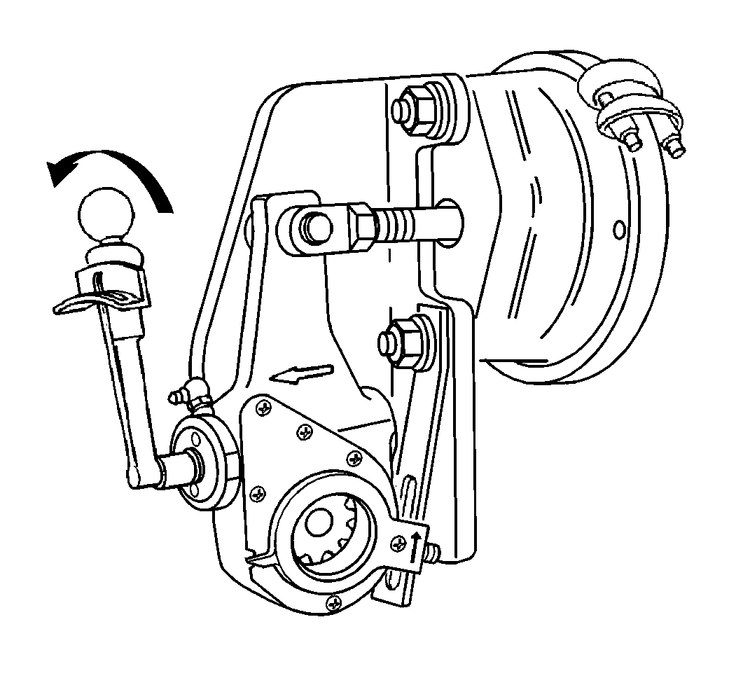
A ratcheting sound occurs during back off. Replace the air brake automatic slack adjuster if the clutch slips at a lesser torque.
