| Subject: | Information on Driveline Vibration Analysis and Correction |
| Models: | 2005-2008 Chevrolet Kodiak C4500/5500 Series |
| 2005-2008 GMC TopKick C4500/5500 Series |
| with 4WD NV273 Transfer Case (RPO NP1) |
This bulletin is being revised to add the 2008 model year and a step under the Strategy Based Diagnostics heading. Please discard Corporate Bulletin Number 06-04-21-004 (Section 04 -- Driveline/Axle).
Background
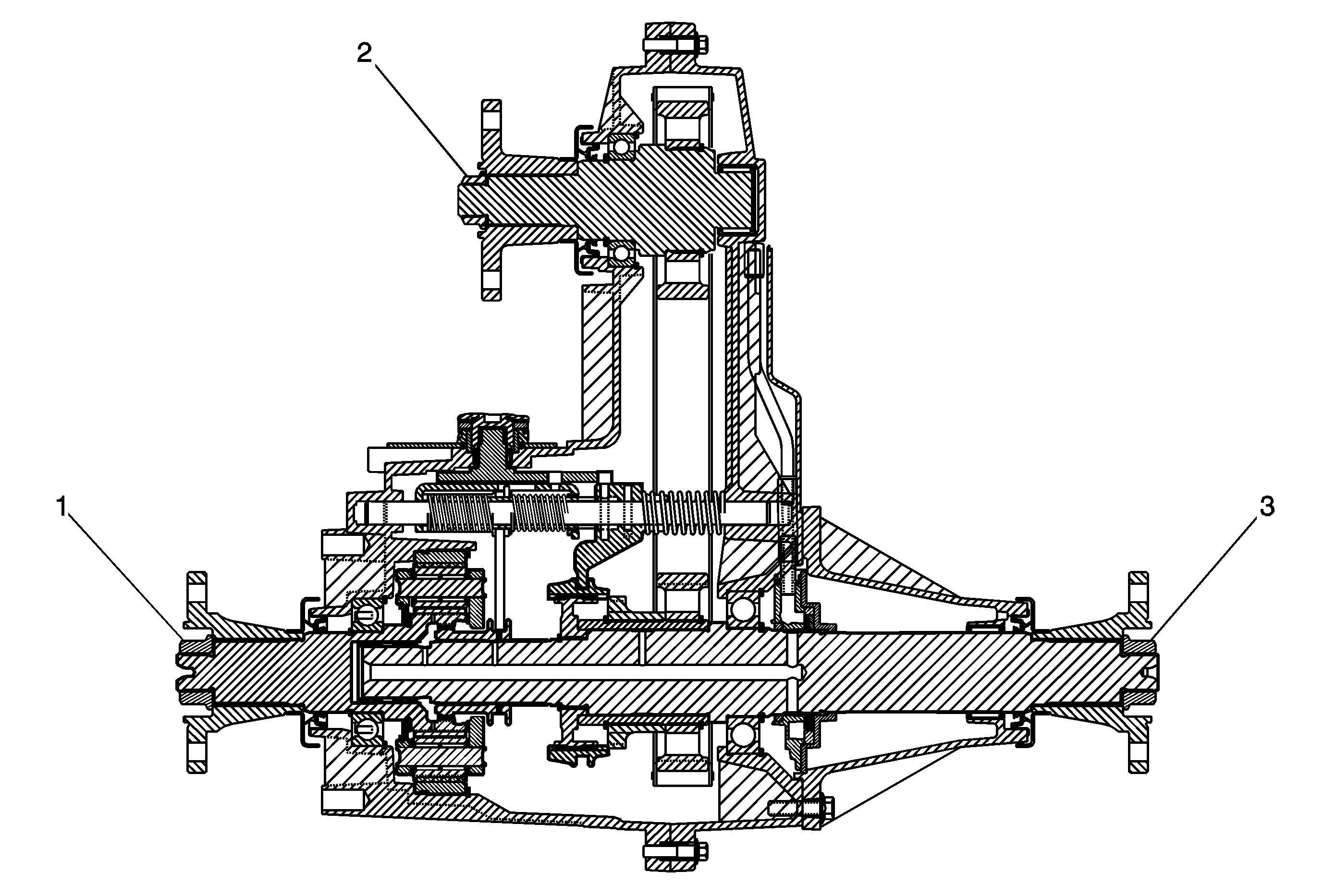
| • | The NV273 transfer case is remote mounted on a bracket behind the transmission allowing for a front input drive shaft along with front and rear output drive shafts. Some radial end play on these flanges is normal as a result of the transfer case
internal stack up. If the radial endplay on each flange is within the specification provided in this document, the transfer case is not to be considered a cause of excessive driveline vibration at highway speeds and does not need to be
replaced.
|
| • | In addition to excessive radial movement on the transfer case flanges, high speed driveline vibration can also result from damaged drive shafts, loose universal joints, incorrect working angles, and unbalanced driveline components. For related information,
refer to Corporate Bulletin Number 06-04-21-003A. |
| • | This document contains radial endplay measurement procedures for the input, front output, and rear output flanges found on the GM NV273 transfer case when installed in the vehicle. |
Strategy Based Diagnostics
- Verify the customer concern. Test drive the vehicle with the customer.
- Make preliminary checks - Complete under vehicle inspection.
- Perform published Diagnostic Checks - Inspect U-Joints. Measure working angles. Use an EVA to determine if the vibration is prop-shaft related or wheel/tire.
- Inspect the transfer case rubber mounts for wear. Replace the mounts if worn.
- Run the engine with the front input shaft removed. If the vibration still exists then the condition is in the engine or transmission. If so, check for an out of balance automatic transmission torque converter.
- Call Technical Assistance if necessary.
Equipment Required
| • | J 45101 - Dial Indicator Set* |
| • | Wire brush or sand paper |
* If the J 45101 - Dial Indicator Set is not available, use a magnetic based dial indicator and follow the Alternative Dial Indicator Mounting Procedure.


