For 1990-2009 cars only
Tools Required
| • | J 34673 Flat Gage Bar |
| • | J 26900-6 Dial Caliper |
| • | J 9617 Pump Seal Installer |
| • | J 36850 Transjel® Lubricant |
Removal Procedure
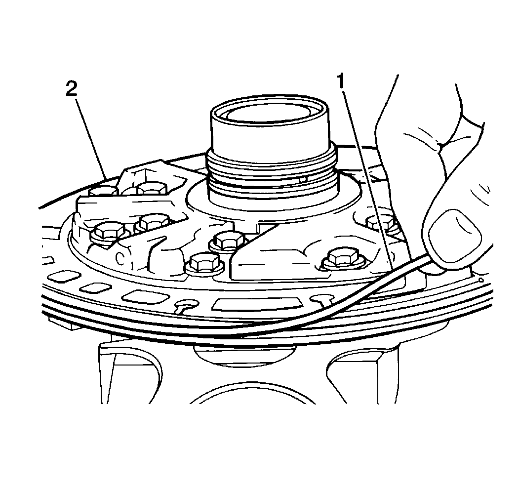
- Remove the fluid pump seal (1) from the fluid pump body (2).
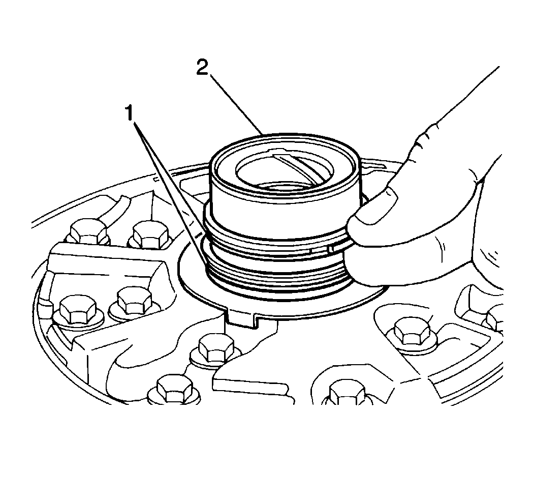
- Remove the stator shaft seal rings (1) from the fluid pump stator shaft (2).
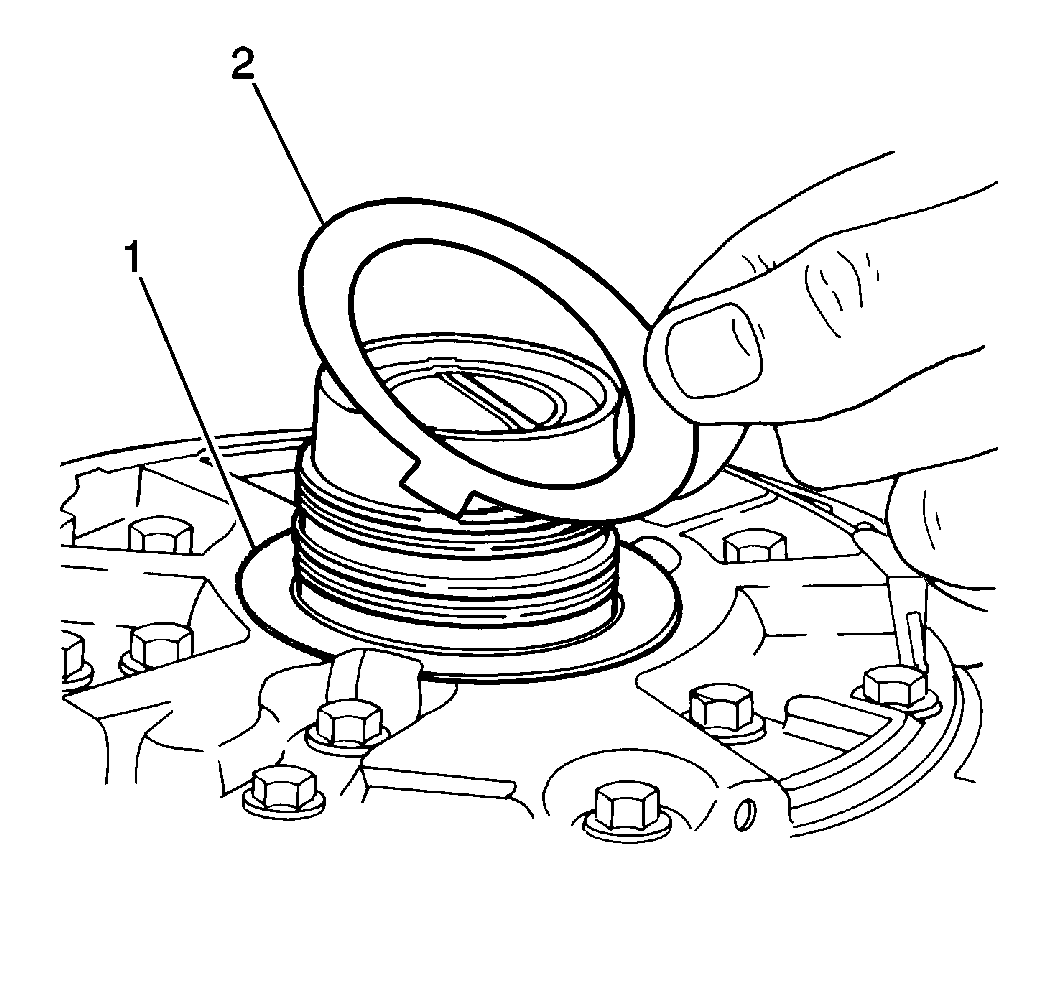
- Remove the fluid pump thrust washer (2) from the rear of the stator shaft cover (1).
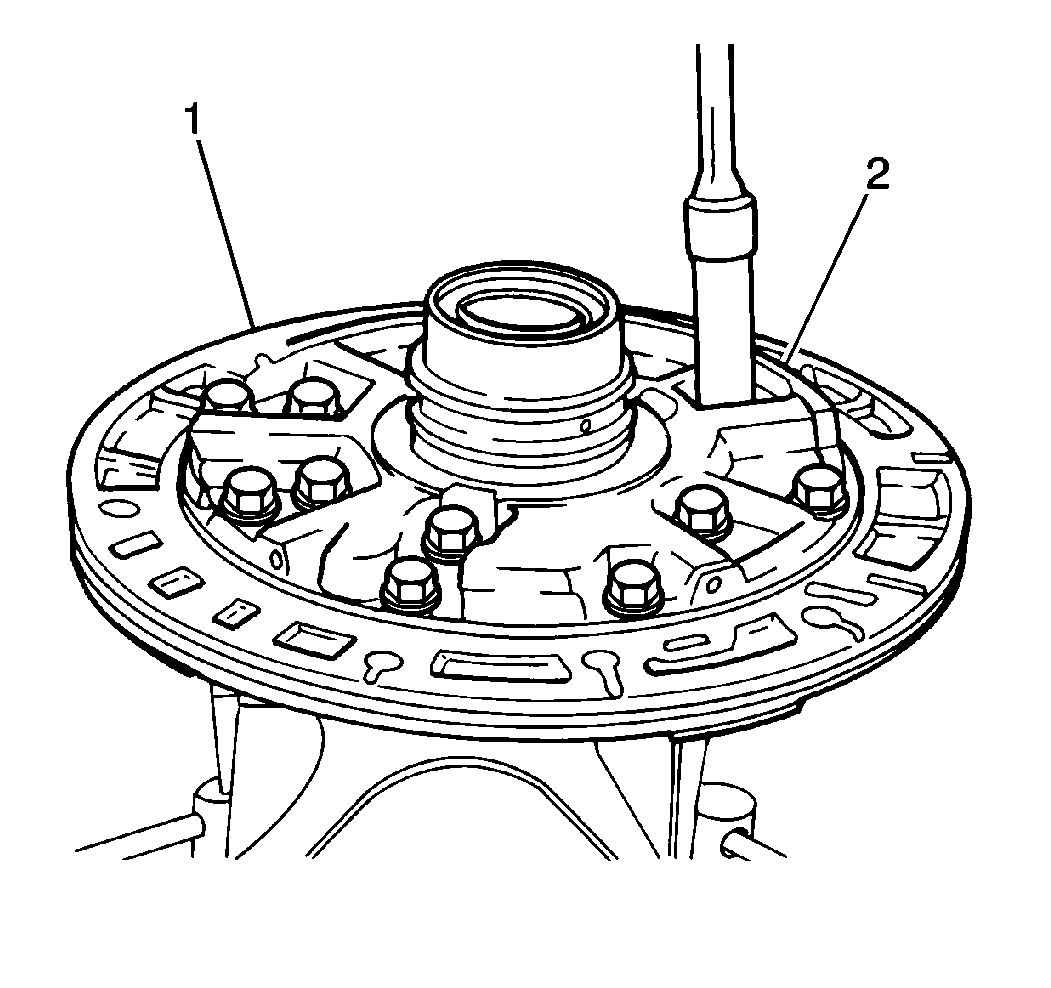
- Remove the eleven stator shaft bolts from the fluid pump body (1).
- Remove the stator shaft (2) from the fluid pump body (1).
- Remove the input shaft seal from the fluid pump body.
- Clean all of the fluid pump components and dry the components thoroughly
- Inspect the following and components for excessive wear or damage and replace as necessary:
- Inspect the fluid pump body and the stator shaft cover mating surfaces for distortion or warp. Replace the fluid pump assembly as necessary.
- Measure the pump body-to-driven gear clearance using a feeler gage (3).
- Measure the fluid pump driven gear tip clearance using a feeler gage (2).
- Use a J 34673 and a feeler gage (1) in order to measure the fluid pump drive gear (3) and the fluid pump driven gear (2) side clearance.
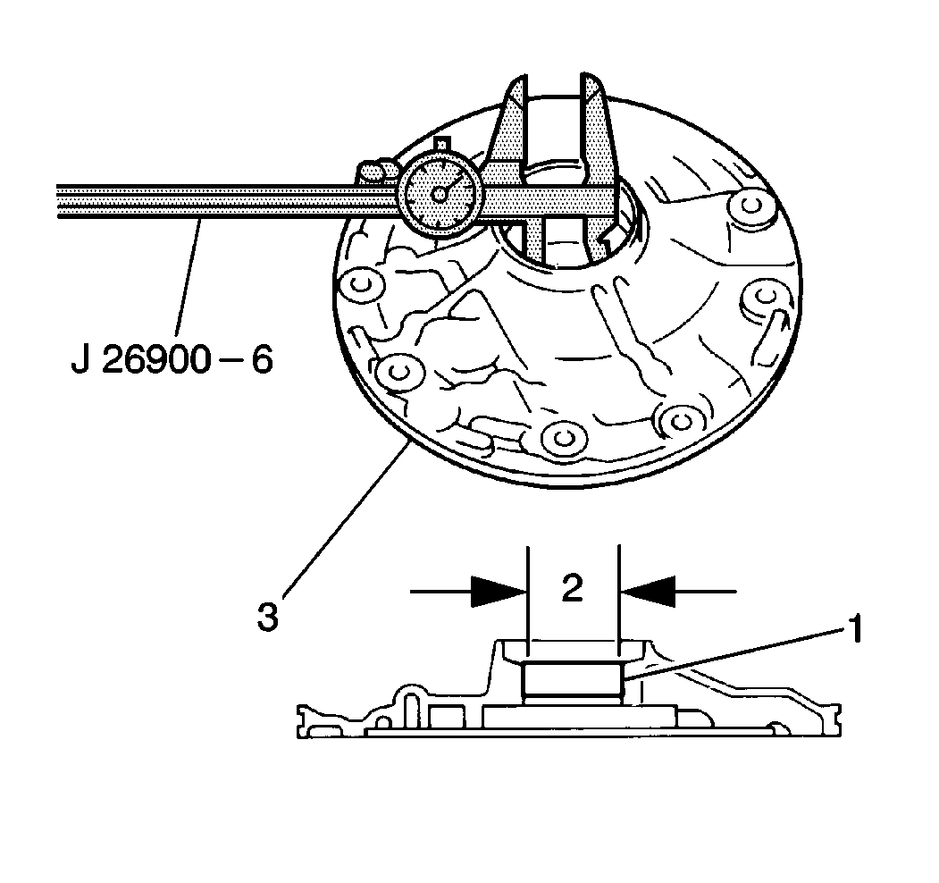
- Use a J 26900-6 in order to measure the fluid pump body bushing (1) inside diameter.
- Use a J 26900-6 in order to measure the inside diameter of the front and rear stator shaft bushings.
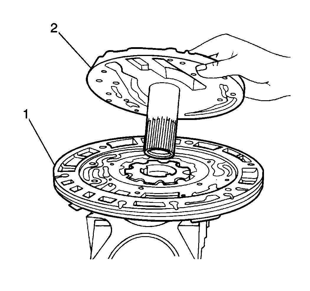
| • | The fluid pump drive gear |
| • | The driven gear |
| • | The stator shaft |
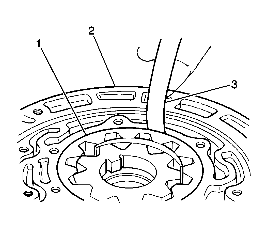
Push the fluid pump driven gear (1) to one side of the fluid pump body (2) and measure the gap on the opposite side.
| • | Standard fluid pump body-to-driven gear clearance should measure between 0.070-0.150 mm (0.0028-0.0059 in). |
| • | If the fluid pump body-to-driven gear clearance exceeds 0.30 mm (0.012 in), replace the fluid pump assembly. |
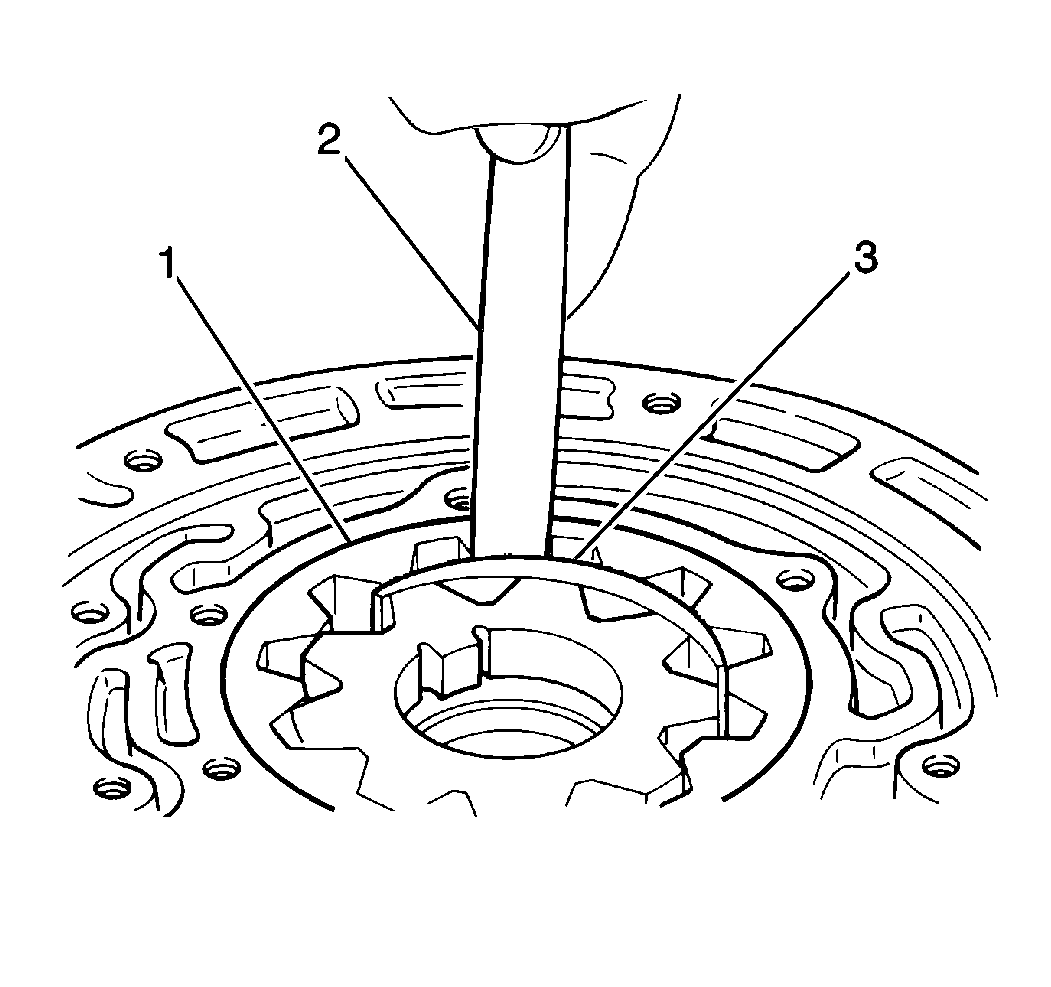
Measure the gap between the fluid pump driven gear teeth (1) and the fluid pump gear crescent (3).
| • | Standard fluid pump driven gear tip clearance should fall within 0.110-0.140 mm (0.0043-0.0055 in). |
| • | If the fluid pump driven gear tip clearance exceeds 0.30 mm (0.012 in), replace the fluid pump assembly. |
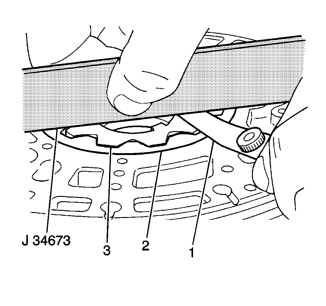
| • | Place the J 34673 across the fluid pump body and measure the clearance between the fluid pump drive gear and the fluid pump driven gear and the fluid pump body mating surface. |
| • | The standard fluid pump drive gear and the fluid pump driven gear side clearance should fall within 0.0020-0.050 mm (0.0008-0.0020 in). |
| • | If the fluid pump drive gear and the fluid pump driven gear side clearance exceeds 0.10 mm (0.004 in), replace the fluid pump body. |
Important: The fluid pump drive gear and the fluid pump driven gear are different sizes. If the thicker of the two gears is not within standard drive gear and driven gear side clearance, replace the fluid pump body.
| • | The maximum fluid pump body bushing inside diameter is 38.180 mm (1.5031 in) (2). |
| • | If the fluid pump body bushing inside diameter is greater than specified, replace the fluid pump body (3). |
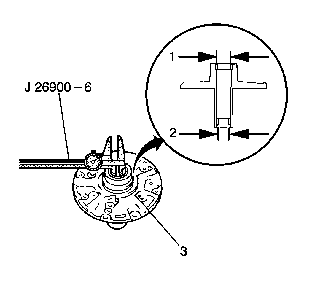
The maximum inside diameter of the front and rear stator shaft bushings is:
| • | Front bushing 21.570 mm (0.8492 in) (1) |
| • | Rear bushing 27.070 mm (1.0657 in) (2) |
| • | If the inside diameter of the front and rear stator shaft bushings is greater than specified, replace the stator shaft |
Installation Procedure
- Use a J 9617 and a hammer in order to install the new input shaft seal into the fluid pump body (2).
- Apply J 36850 to the new input shaft seal lip.
- Connect the stator shaft (1) onto the fluid pump body, securing with 11 bolts.
- Apply J 36850 to the fluid pump thrust washer in order to hold it on the rear of the stator shaft cover.
- Install the fluid pump thrust washer onto the rear of the stator shaft cover.
- Install two new seal rings onto the fluid pump stator shaft.
- Install the new fluid pump seal onto the fluid pump body.
- Inspect the fluid pump drive gear for smooth rotation by carefully inserting two small drift punches into the fluid pump body and turning the fluid pump drive gear.
Notice: Refer to Fastener Notice in the Preface section.
Tighten
Tighten the stator shaft-to-fluid pump body bolts to 10 N·m (89 lb in).
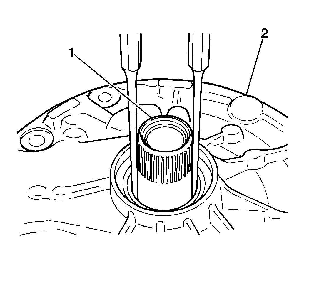
If the fluid pump drive gear does not rotate smoothly, repair or replace the pump, as necessary.
