Tools Required
| • | J 37271 Countershaft
Locknut Spanner Wrench |
| • | J 36513 Large Bearing
Split Plate |
| • | J 37273
Countershaft
Pressing Button |
| • | J 35287 Countershaft
Bearing Race Installer |
| • | J 37278 Countershaft
Inner Race Support Disc |
Removal Procedure
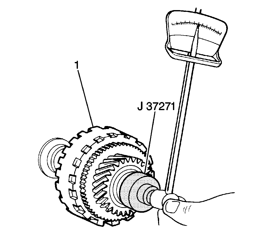
- Use a J 37271
and a torque wrench to measure the countershaft drive pinion bearing
preload (countershaft starting torque) before disassembly.
| • | Place the countershaft drive pinion (1) in a soft jaw vise and
turn the countershaft front lock nut with a J 37271
and a torque wrench. |
| • | The countershaft requires approximately 0.6-1.0 N·m
(5.3-8.8 lb in) to rotate. |
| • | If the countershaft drive pinion bearing preload does not fall within
specification, inspect the countershaft assembly components for excessive wear. |
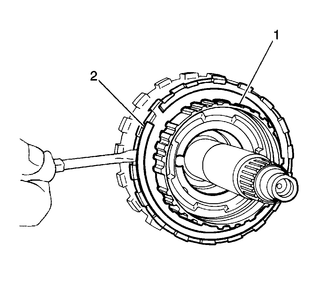
- Remove the underdrive planetary carrier
snap ring (2) from the countershaft drive pinion (1).
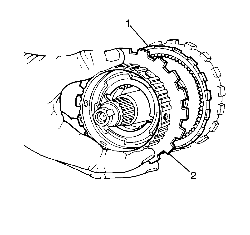
- Remove the underdrive planetary carrier (2)
from the countershaft drive pinion (1).
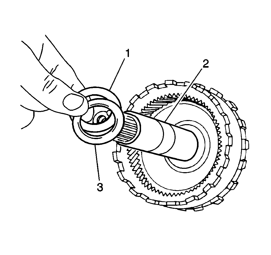
- Remove the underdrive sun gear outer thrust
bearing (1) and the race (3) from the countershaft (2).
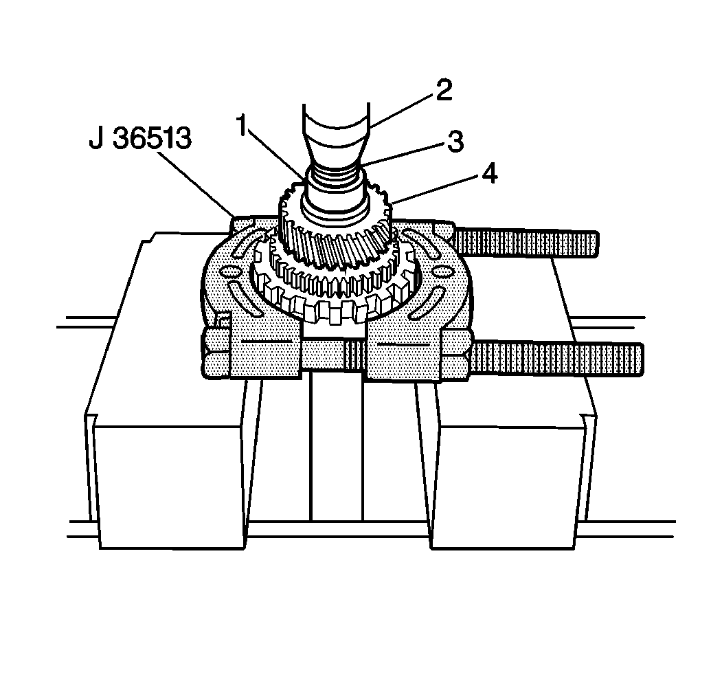
- Use the J 37273
with a J 36513
and a hydraulic press (2) to remove the following components from the countershaft:
| • | The countershaft front roller bearing inner race |
| • | The countershaft outer drive pinion bearing |
| • | The countershaft drive pinion |
- Remove the crush sleeve from the countershaft.
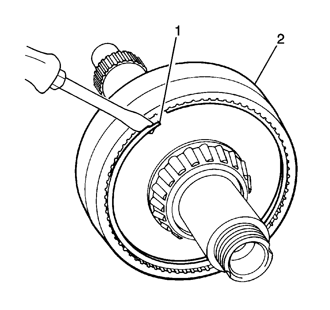
- Remove the following components from the
underdrive planetary ring gear flange on the countershaft:
| • | The underdrive planetary ring gear snap ring (1) |
| • | The underdrive planetary ring gear (2) |
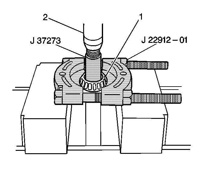
- Use the J 37273
with a J 22912-01
and a hydraulic press (2) to remove the countershaft inner drive pinion bearing (1)
from the countershaft.
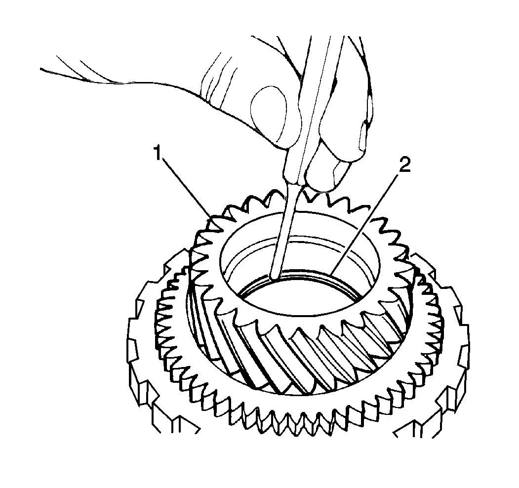
- Use a standard drift punch and a hammer
to remove the countershaft inner drive pinion bearing race (2) from the countershaft
drive pinion.
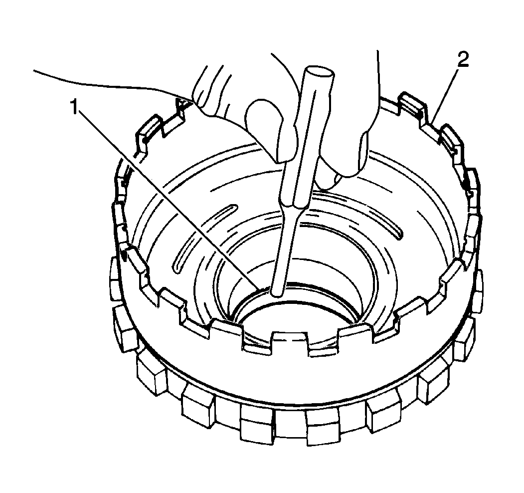
- Use a standard drift punch and a hammer
to remove the countershaft outer drive pinion bearing race (1) from the countershaft
drive pinion (2).
- Clean all countershaft assembly components and dry thoroughly.
- Inspect all countershaft assembly bearings and races for rough operation,
excessive wear or damage and replace as necessary.
- Inspect the countershaft drive pinion gear and parking gear for chipped
or broken teeth, excessive wear or damage. Replace the countershaft drive pinion
as necessary.
- Inspect the following components for excessive wear or damage and replace
as necessary:
| • | The underdrive planetary ring gear |
| • | The underdrive planetary carrier |
| • | The underdrive sun gear |
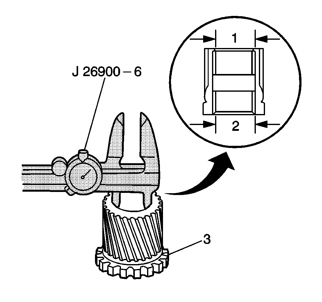
- Use the J 26900-6
to measure the underdrive sun gear flange bushing inside diameter.
| • | The standard underdrive sun gear flange inside diameter should fall within
29.800 to 29.825 mm (1.1735 to 1.1742 in). |
| • | The maximum sun gear flange bushing inside diameter is 29.870 mm
(1.1760 in). |
| • | If the underdrive sun gear flange bushing inside diameter is greater
than specified, replace the underdrive sun gear (3). |
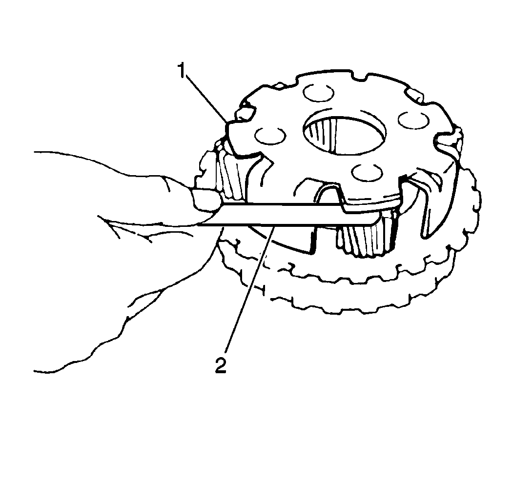
- Use a feeler gage (2) to measure
the underdrive planetary carrier pinion gear (1) thrust clearance.
| • | Standard underdrive planetary carrier pinion gear thrust clearance should
fall within 0.20 to 0.50 mm (0008 to 0.020 in). |
| • | If the underdrive planetary carrier pinion gear thrust clearance is greater
than 0.50 mm (0.020 in), replace the underdrive planetary carrier. |
Installation Procedure
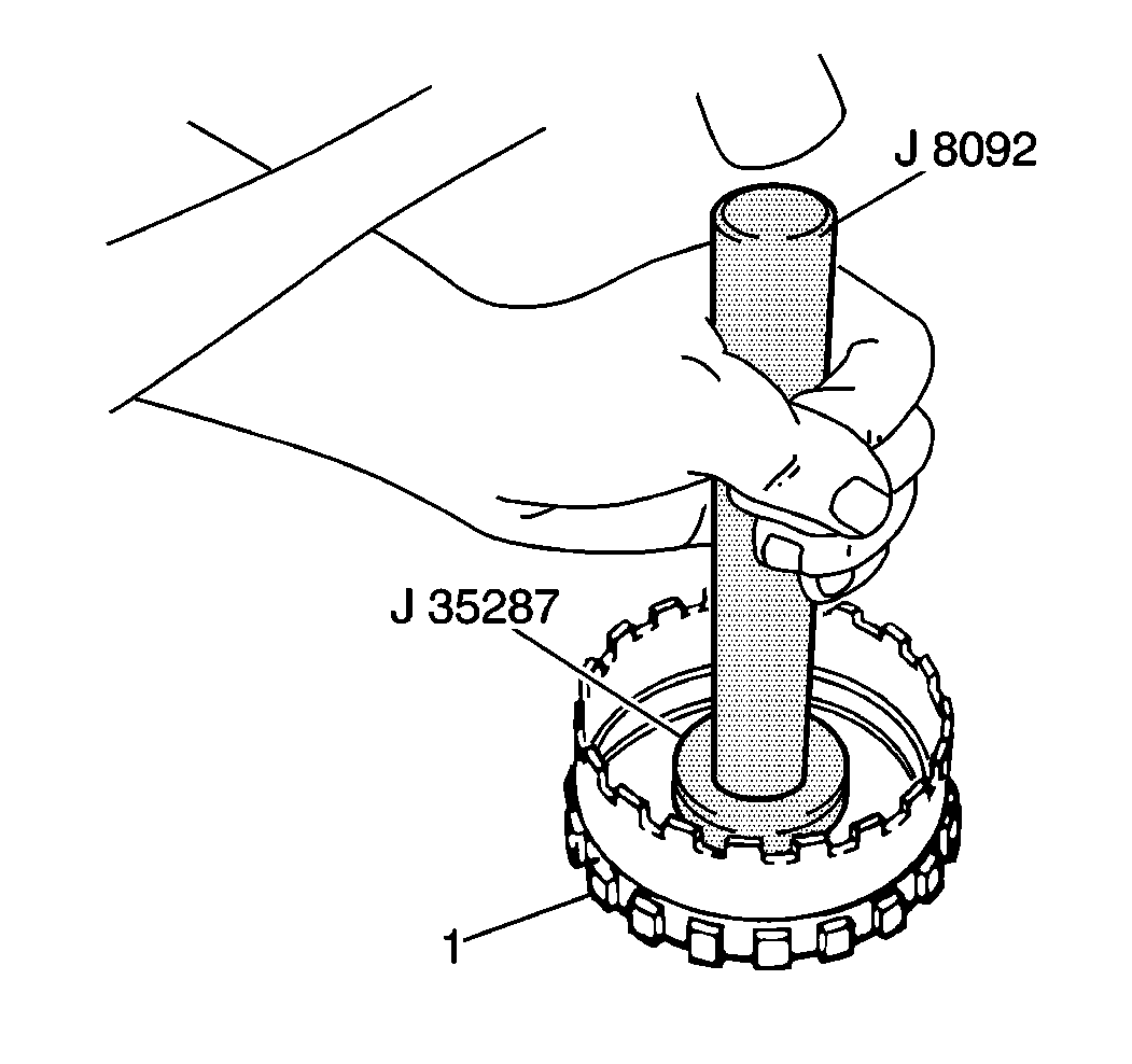
- Use the J 35287
with a J 8092
and
a hammer to install the countershaft inner drive pinion bearing race into the countershaft
drive pinion (1).
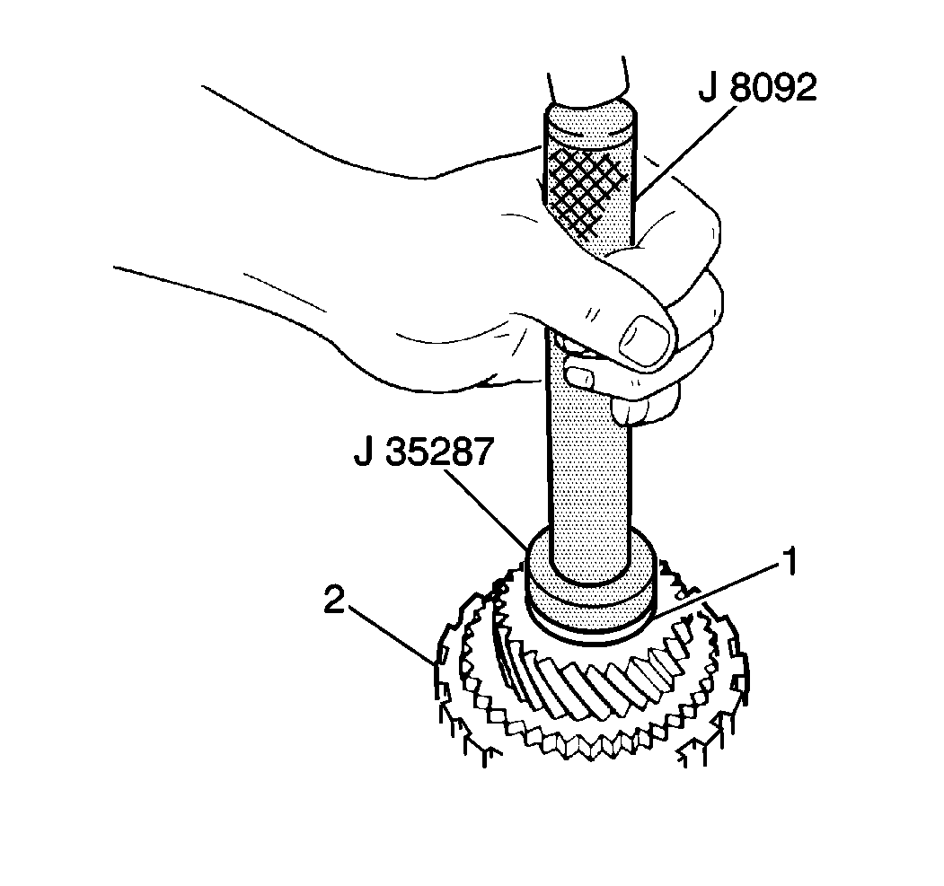
- Use the J 35287
with a J 8092
and
a hammer to install the countershaft outer drive pinion bearing race into the countershaft
drive pinion (2).
Important: In order to achieve true and accurate countershaft
drive pinion bearing preload, the countershaft drive pinion must be rotated during
the installation of the countershaft drive pinion bearing (3) to
ensure that the new crush sleeve is not collapsed before countershaft drive pinion
preload can be adjusted. It is recommended that the countershaft drive pinion and
outer drive pinion bearing be installed first and then the countershaft front roller
bearing inner race. This is to allow the technician to rotate the countershaft drive
pinion during outer drive pinion bearing installation. If the countershaft drive
pinion will not rotate, or is hard to rotate after outer drive pinion bearing installation,
the crush sleeve has been collapsed and must be replaced with a new crush sleeve.
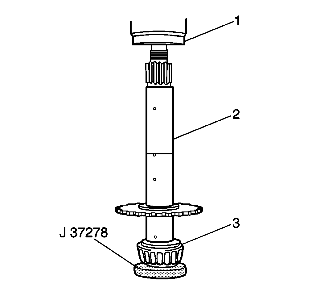
- Use the J 37278
and a hydraulic press to install the countershaft inner drive pinion
bearing (3) onto the countershaft (2).
- Install the underdrive planetary ring gear onto the underdrive planetary
ring gear flange on the countershaft, securing with the underdrive planetary ring
gear snap ring.
- Install the new crush sleeve onto the countershaft.
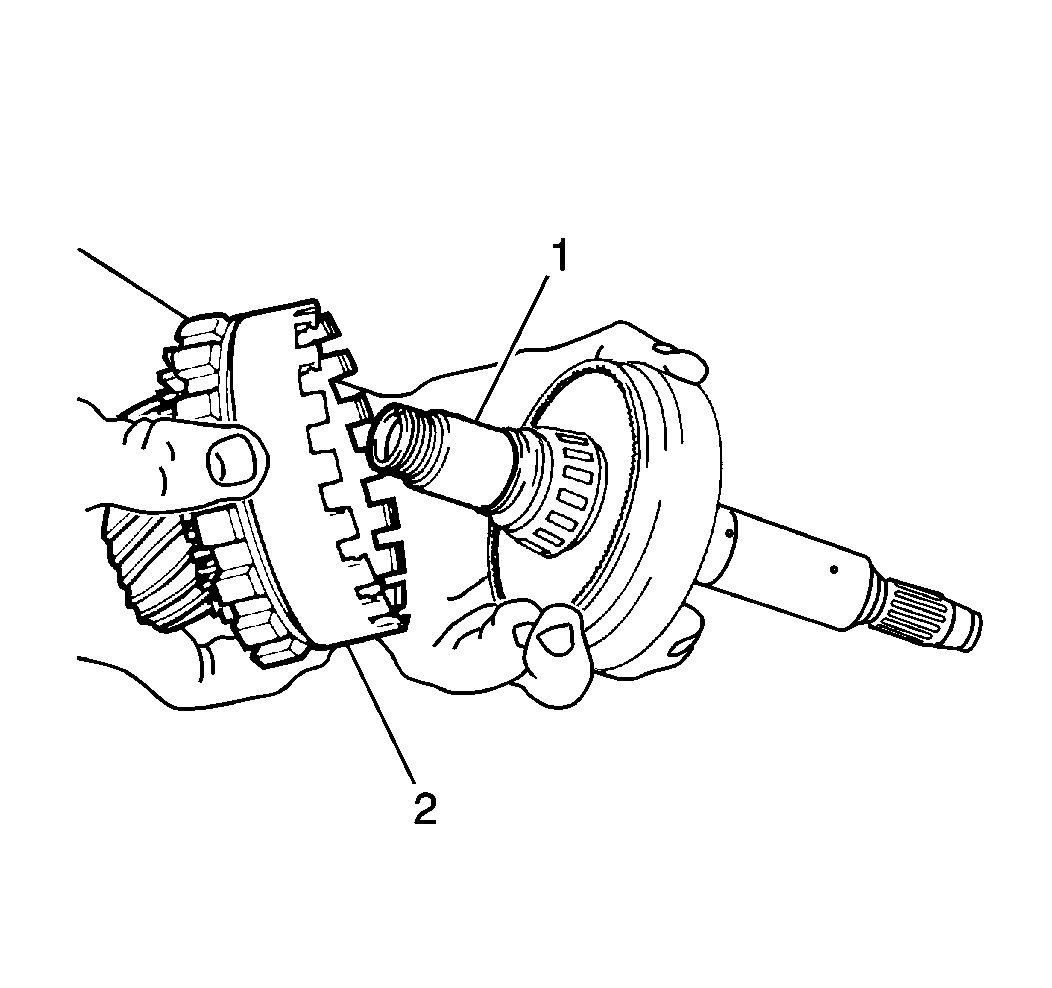
- Use the J 37278
and a hydraulic press to install the countershaft drive pinion and
outer drive pinion bearing onto the countershaft (1) while rotating the countershaft
drive pinion (2).
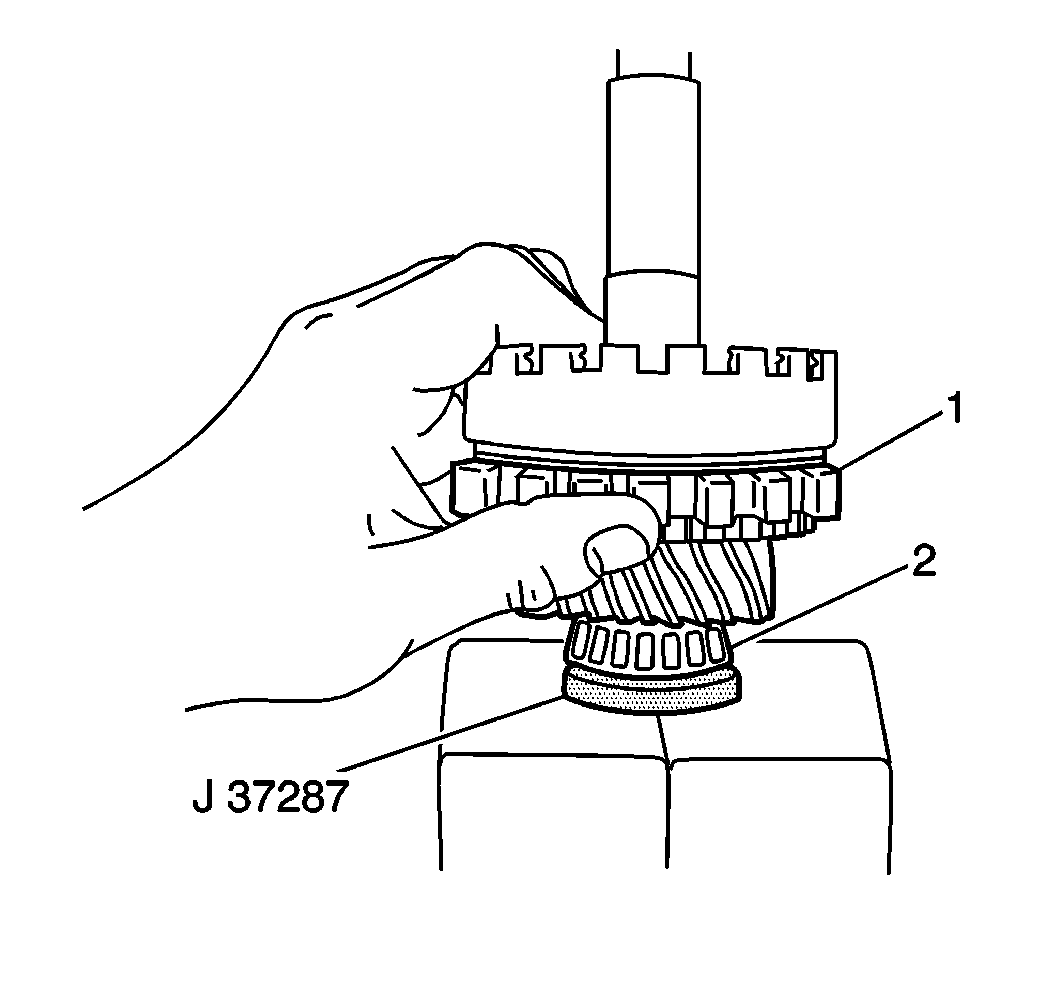
- Use the J 37278
and a hydraulic press to install the countershaft outer drive pinion
bearing (2) onto the countershaft while rotating the countershaft
drive pinion.
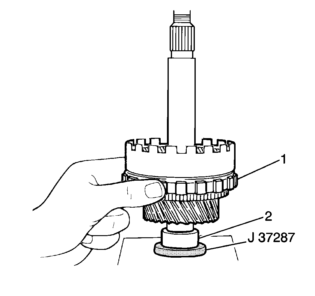
- Use the J 37278
and a hydraulic press to press the countershaft front roller bearing
inner race onto the countershaft (1); leaving a small space between the countershaft
front roller bearing inner race and the outer drive pinion bearing.
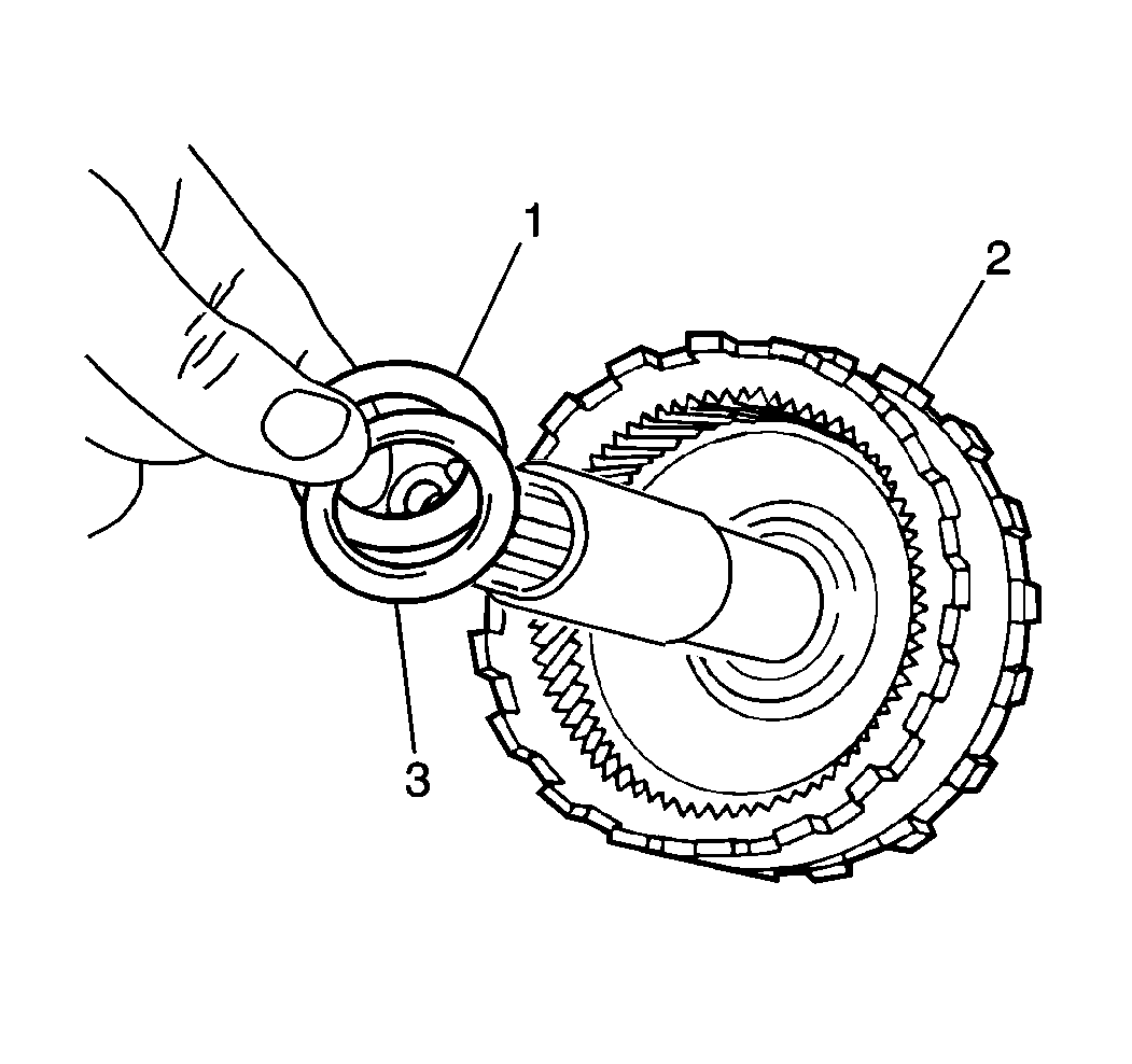
- Install the underdrive sun gear outer thrust
bearing (1) and race (3) onto the countershaft.
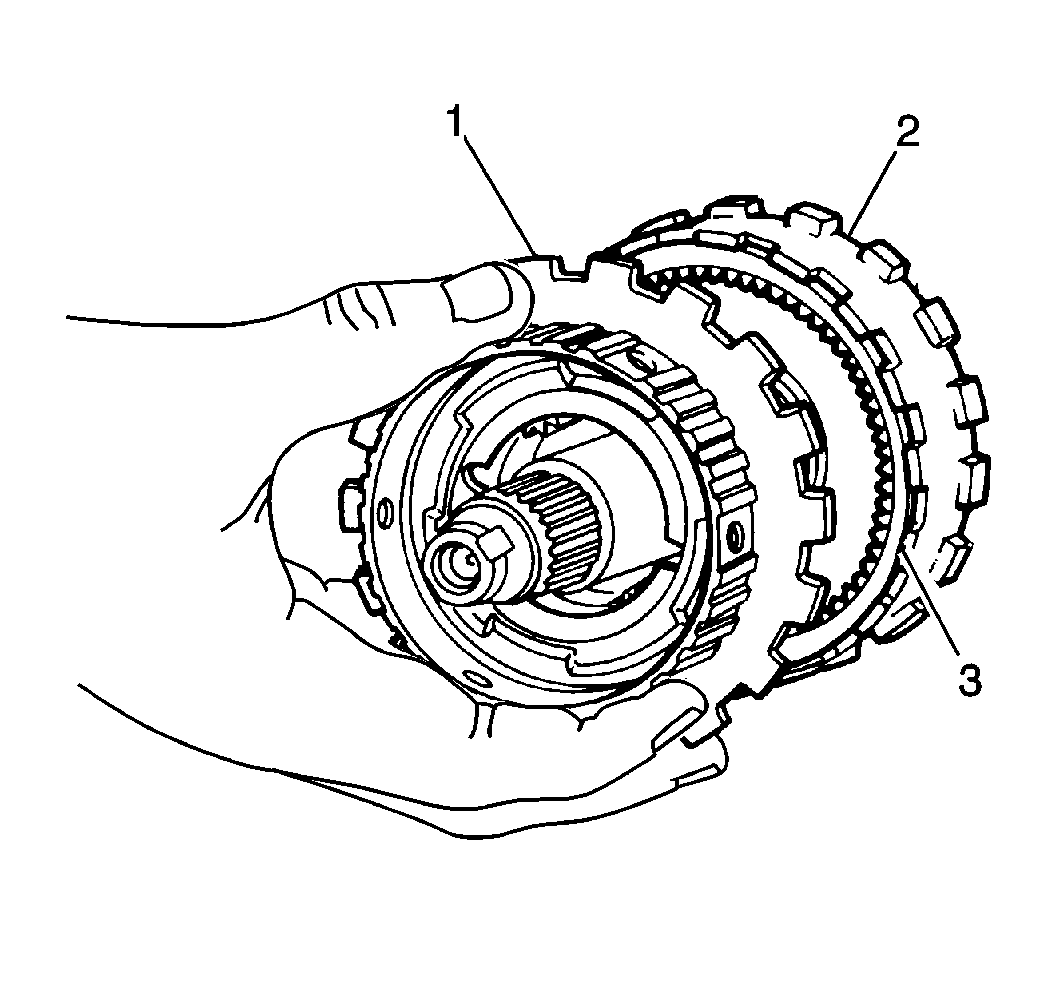
- Install the underdrive planetary carrier (1)
into the countershaft drive pinion.
- Install the underdrive planetary carrier snap ring into the countershaft
drive pinion (2).
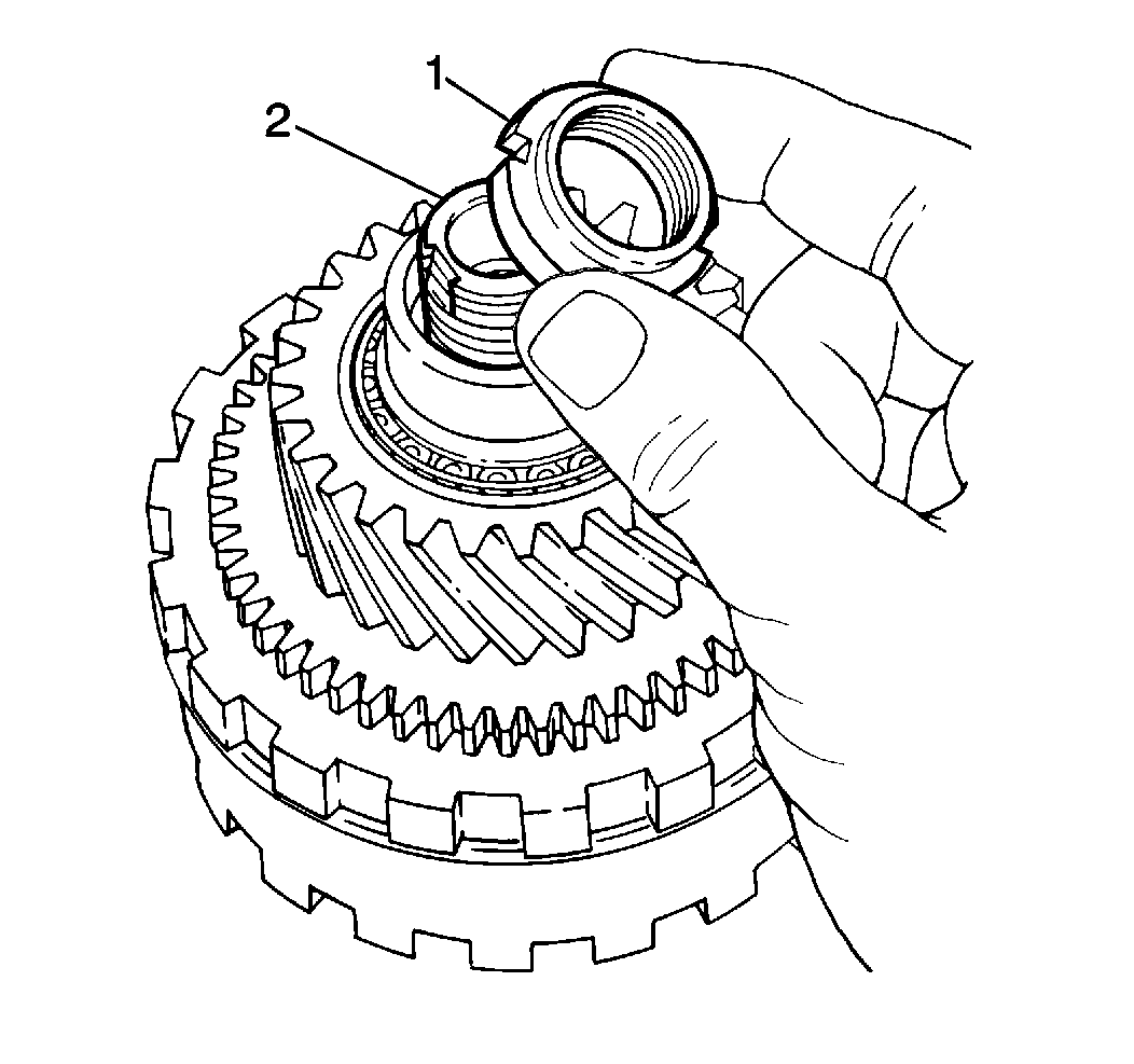
- Install the front countershaft locknut (1)
onto the countershaft. Do not tighten fully.
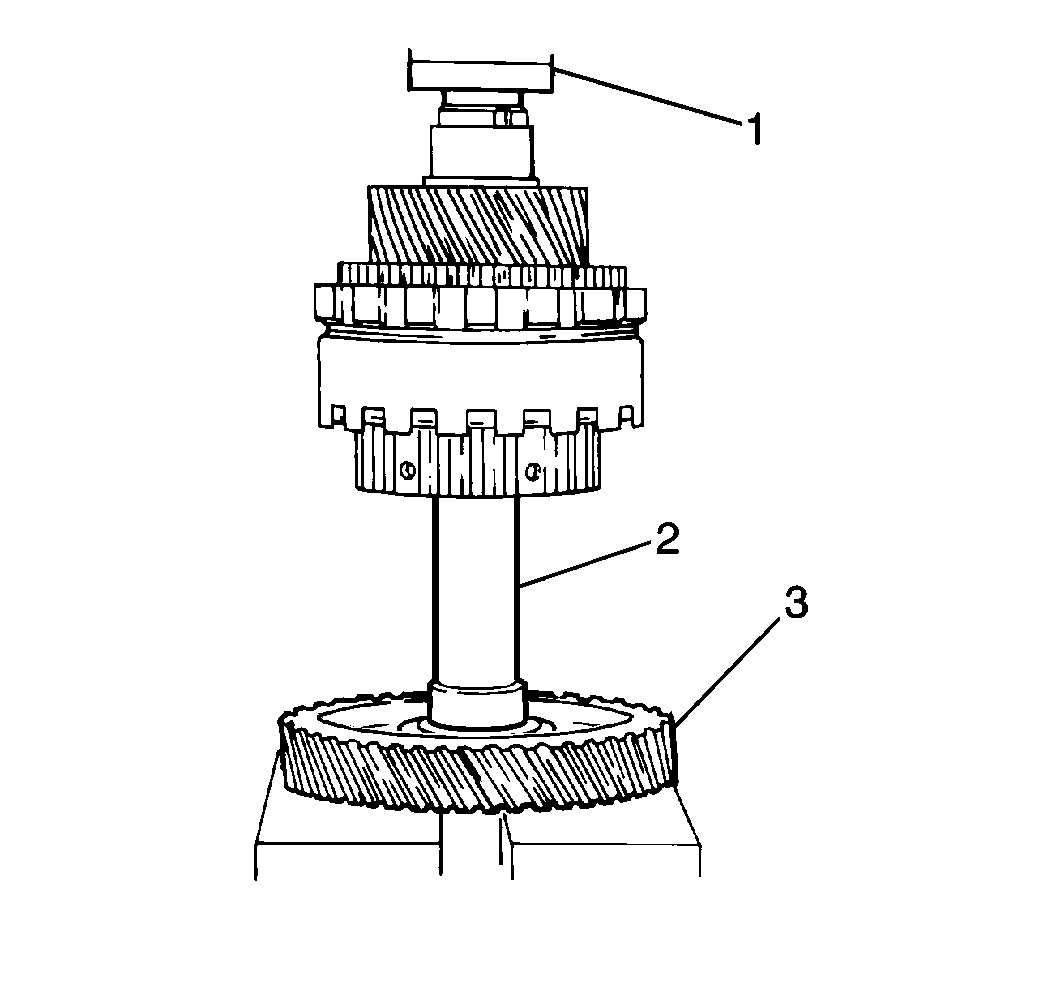
- Use a J 37271
and a torque wrench to adjust the countershaft drive pinion bearing
preload (countershaft starting torque).
| • | Temporarily install the countershaft driven gear (3) onto the
countershaft using a hydraulic press. |
| • | Use a J 34826
to
temporarily install the countershaft driven gear locknut onto the countershaft. |
| • | Place the countershaft assembly in a soft jaw vise, holding the countershaft
assembly by the countershaft driven gear locknut. |
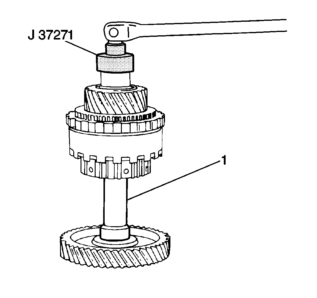
- Use a J 37271
to tighten the front countershaft locknut gradually in increments
of 5 N·m (44 lb in).
- Between each tightening increment, remove the countershaft assembly from
the soft vise and place the countershaft drive pinion in the soft jaw vise so that
the countershaft (1) is able to rotate.
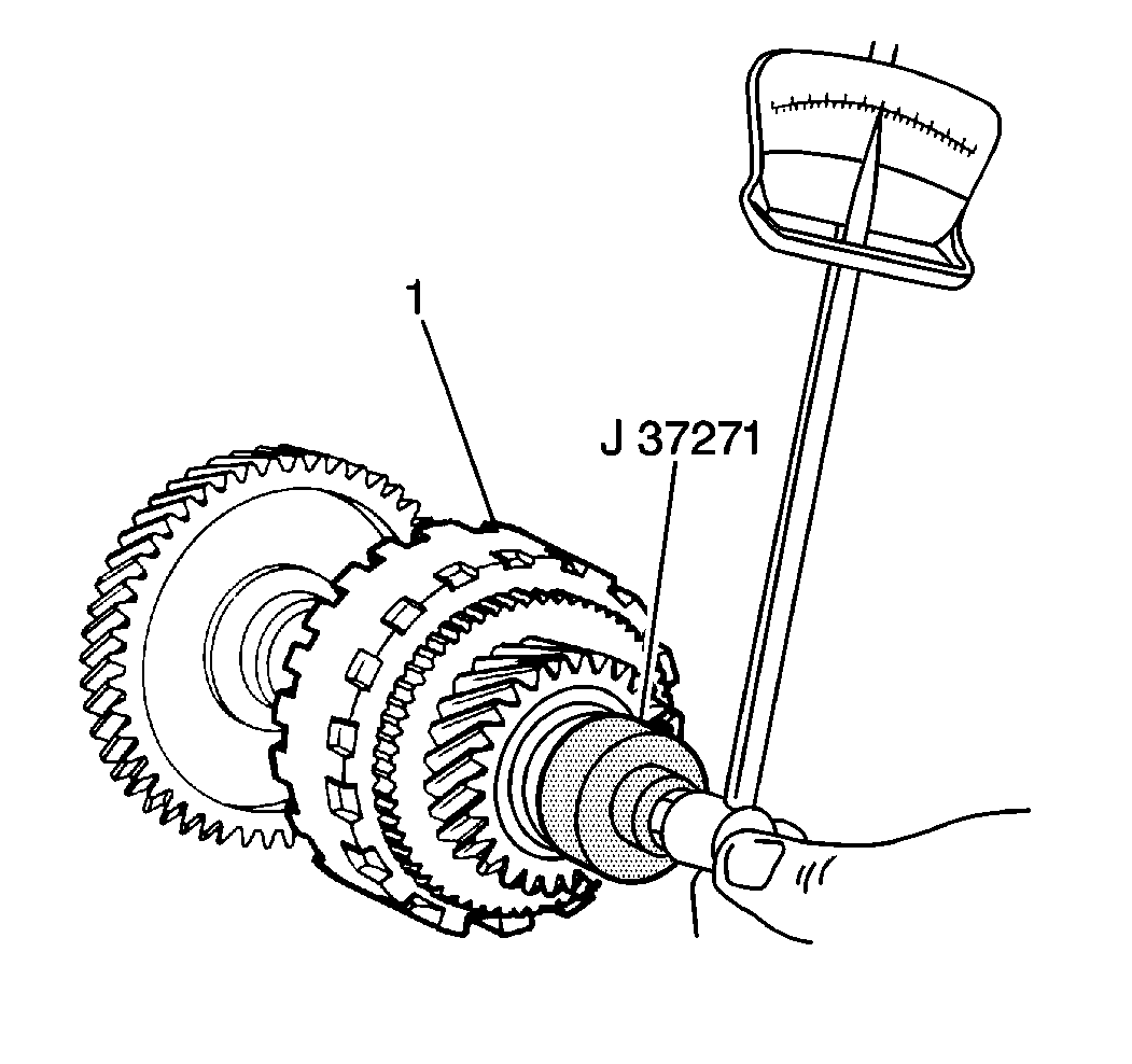
- Use the J 37271
and a torque wrench to measure the countershaft drive pinion bearing
preload (countershaft starting torque) between each increment of tightening.
The countershaft should require the following approximate specifications to
rotate:
| • | For new bearings: 0.6-1.0 N·m (5.30-8.80 lb in) |
| • | For reused bearings: 0.3-0.5 N·m (2.60-4.3 lb in) |
| • | If the countershaft drive pinion bearing preload does not fall within
specification, inspect the countershaft assembly components for excessive wear. |
- Remove the countershaft drive pinion from the soft jaw vise.
- Use a J 34826
to
remove the countershaft driven gear locknut.
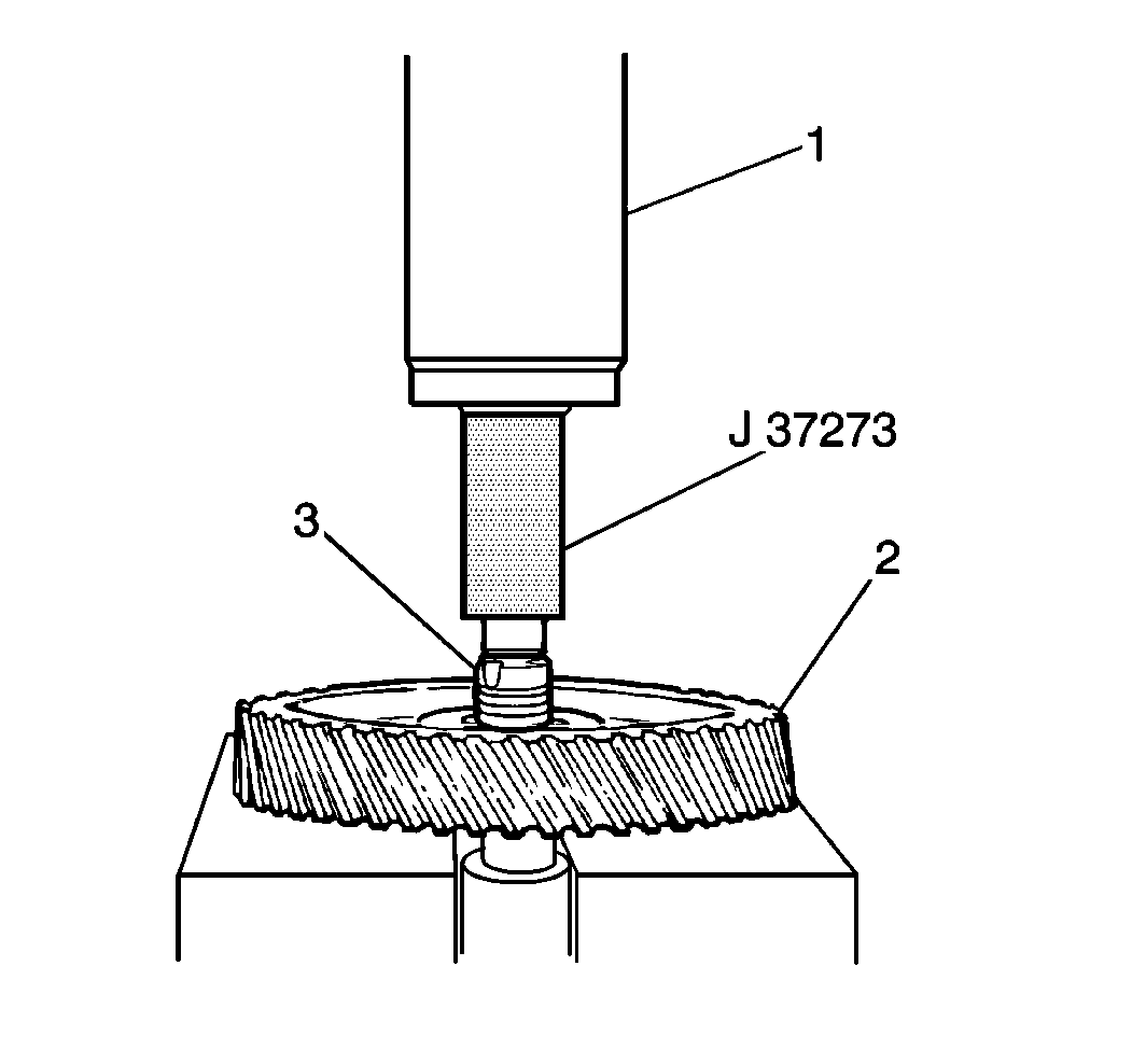
- Use a J 37273
and a hydraulic press (1) in order to remove the countershaft
driven gear (2) from the countershaft (3).
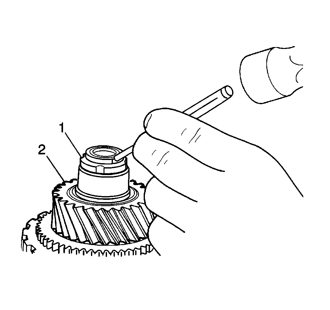
- Stake the front countershaft locknut (1).


