Tools Required
| • | J 36850 Transjel® Transmission Assembly Lubricant. |
| • | J 26900-6 Dial Caliper. |
Notice: If the 2nd coast brake band appears excessively worn or damaged and replacement is necessary, the new brake band should be soaked in Dexron®-III Automatic Transmission Fluid GM P/N 12346143, or equivalent, for two hours prior to installation. This causes the band material to permeate with fluid which will prevent the band overheating on first time application.
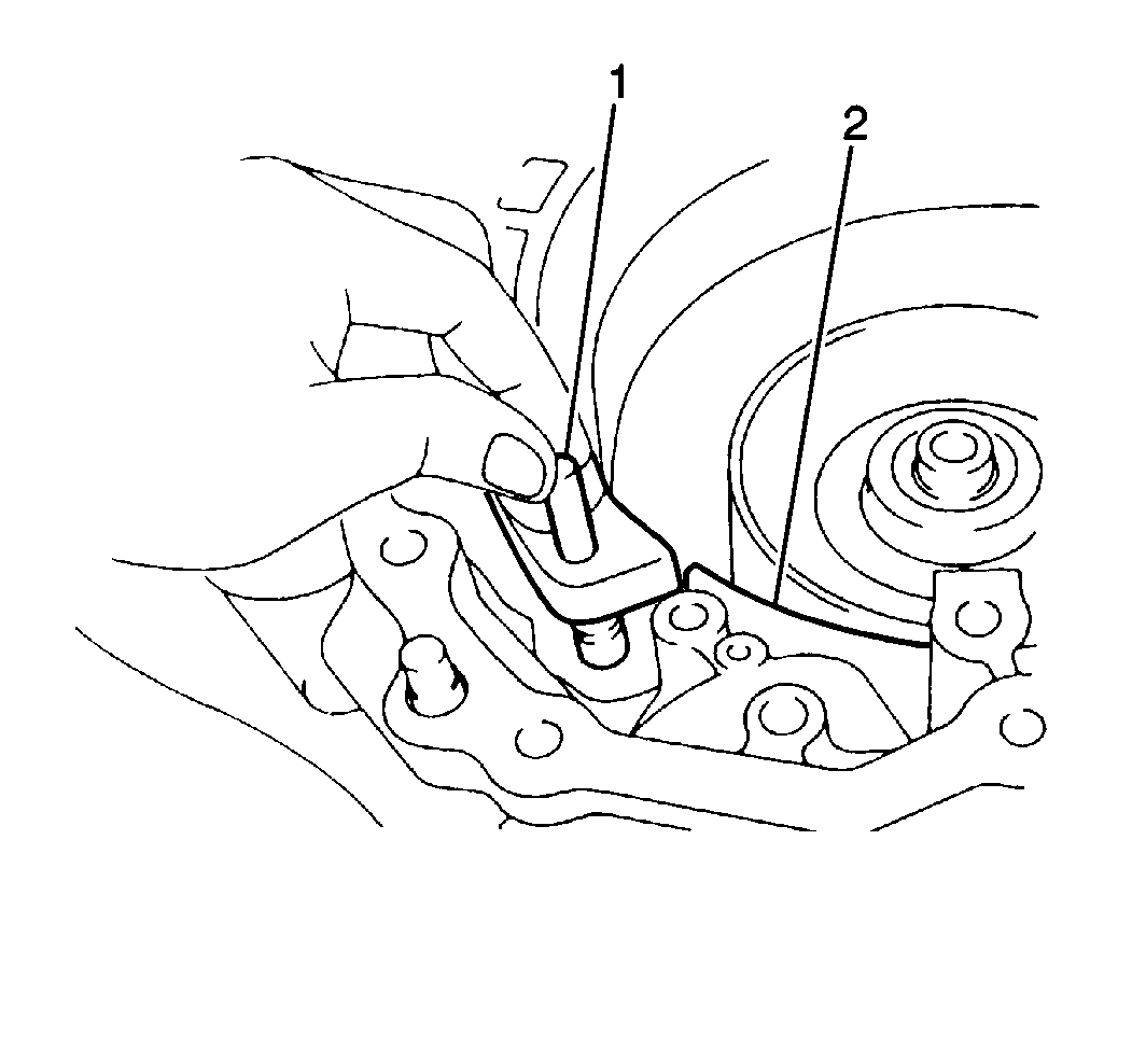
- Install the 2nd coast brake band (2) into the transaxle case. Secure the brake band with the 2nd coast brake band anchor pin (1).
- Apply J 36850 to the outer forward clutch thrust bearing.
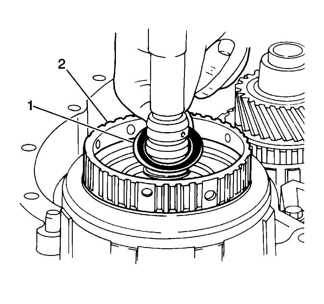
- Install the forward clutch outer thrust bearing (1) over the input shaft and into the forward clutch drum.
- Install the direct clutch thrust washer onto direct clutch drum.
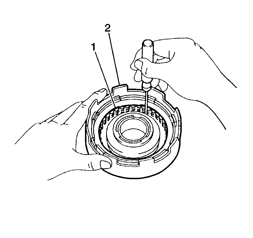
- Align the inner teeth of the direct clutch discs (1).
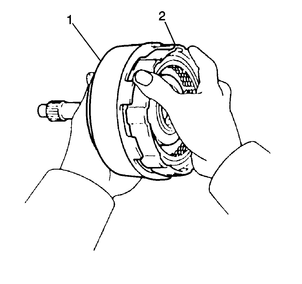
- Install the direct clutch assembly (1) onto the forward clutch assembly (2) by rotating the direct clutch drum back and forth until the direct clutch inner teeth of the direct clutch discs mesh with the forward clutch drum.
- Align the inner teeth of the forward clutch discs.
- Apply J 36850 to the forward clutch inner thrust bearing in order to hold it in place in the center of the forward clutch drum.
- Install the forward clutch inner thrust bearing into the center of the forward clutch drum.
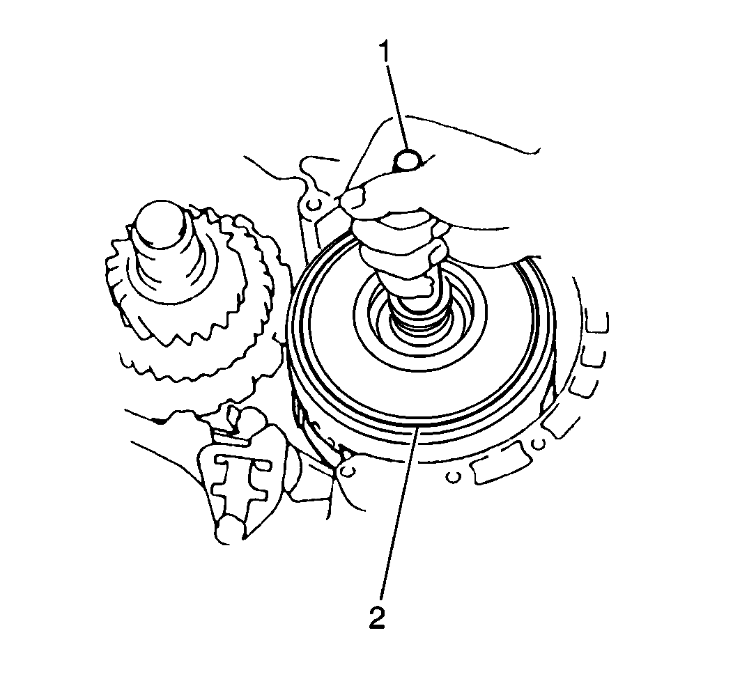
- Install the forward and direct clutch assemblies (2) onto the front planetary ring gear by rotating the input shaft (1) back and forth until the inner teeth of the forward clutch discs mesh with the front planetary ring gear.
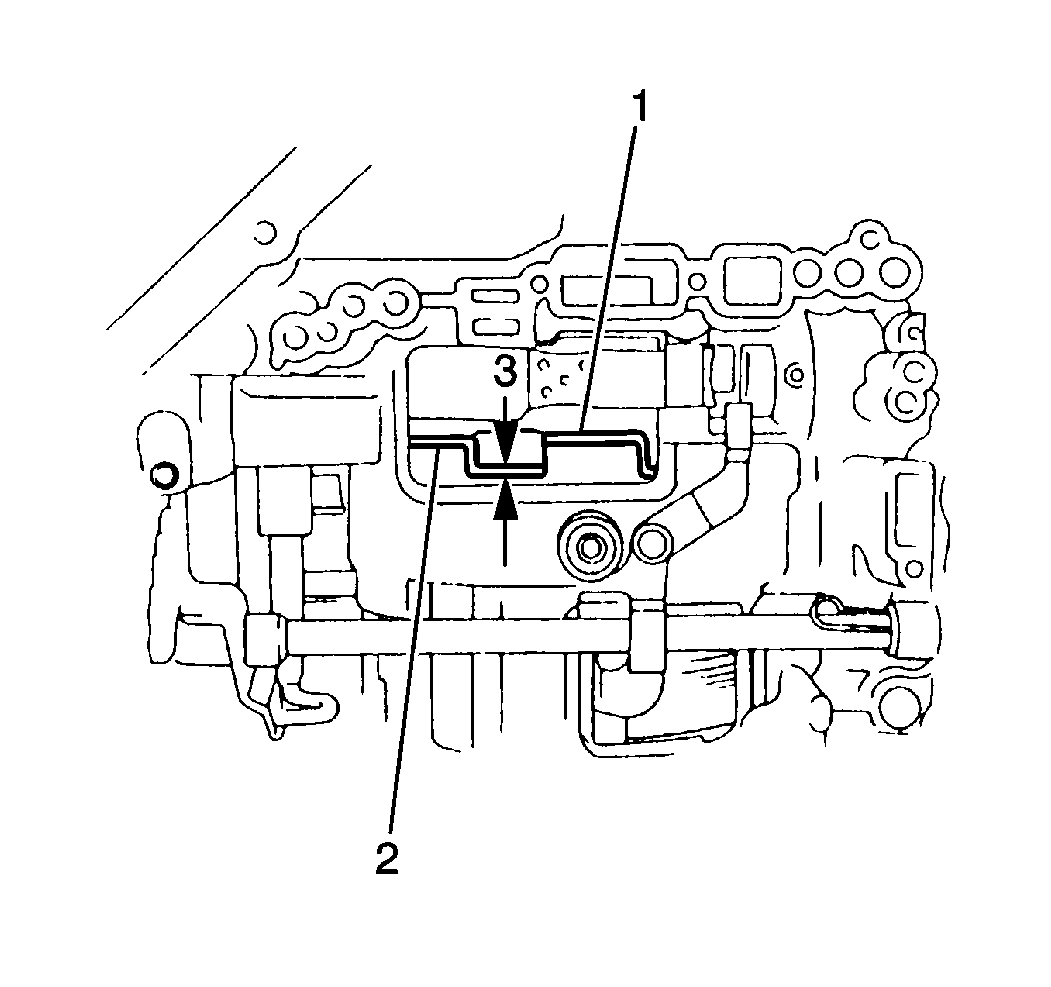
- Measure the installation depth of the forward and the direct clutch assemblies by measuring the gap between the direct clutch drum (1) and the sun gear input drum using a J 26900-6 .
- Verify that the gap between the direct clutch drum and the sun gear input drum (2) is approximately 3 mm (0.118 in) (3).
- If the gap between the direct clutch drum and the sun gear input drum is greater than specification, remove the forward and direct clutch assemblies and reinstall until the distance is within specification.
- Apply J 36850 to the 2nd coast brake servo piston and cover seals.
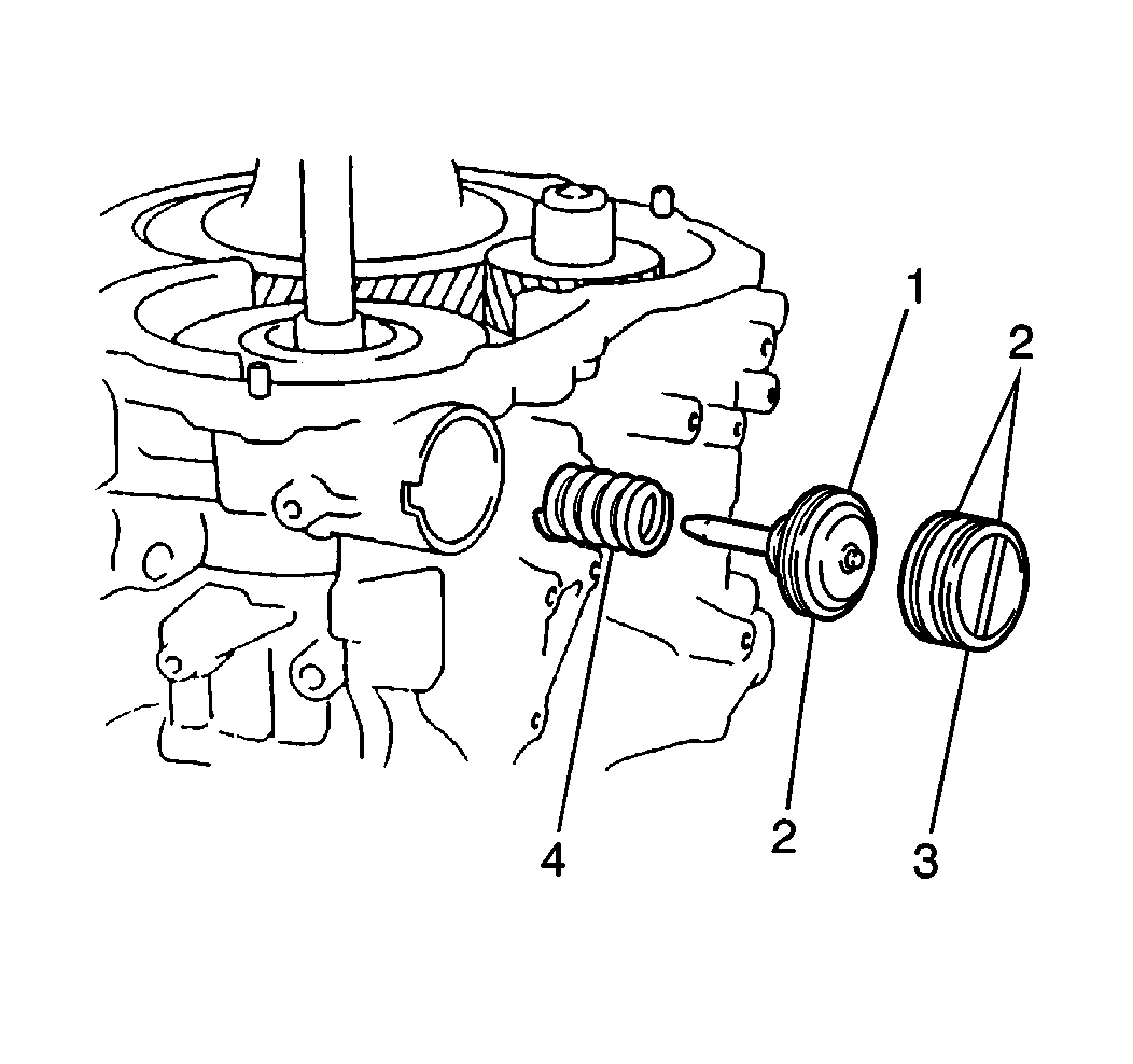
- Install the 2nd coast brake outer return spring (4), the 2nd coast brake piston (1) and the 2nd coast brake servo cover (3) into the transaxle case.
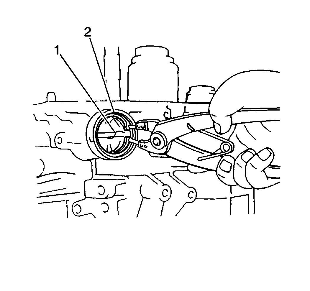
- Install the 2nd coast brake servo cover snap ring (2) into the transaxle case.
- Measure the 2nd coast brake servo piston stroke.
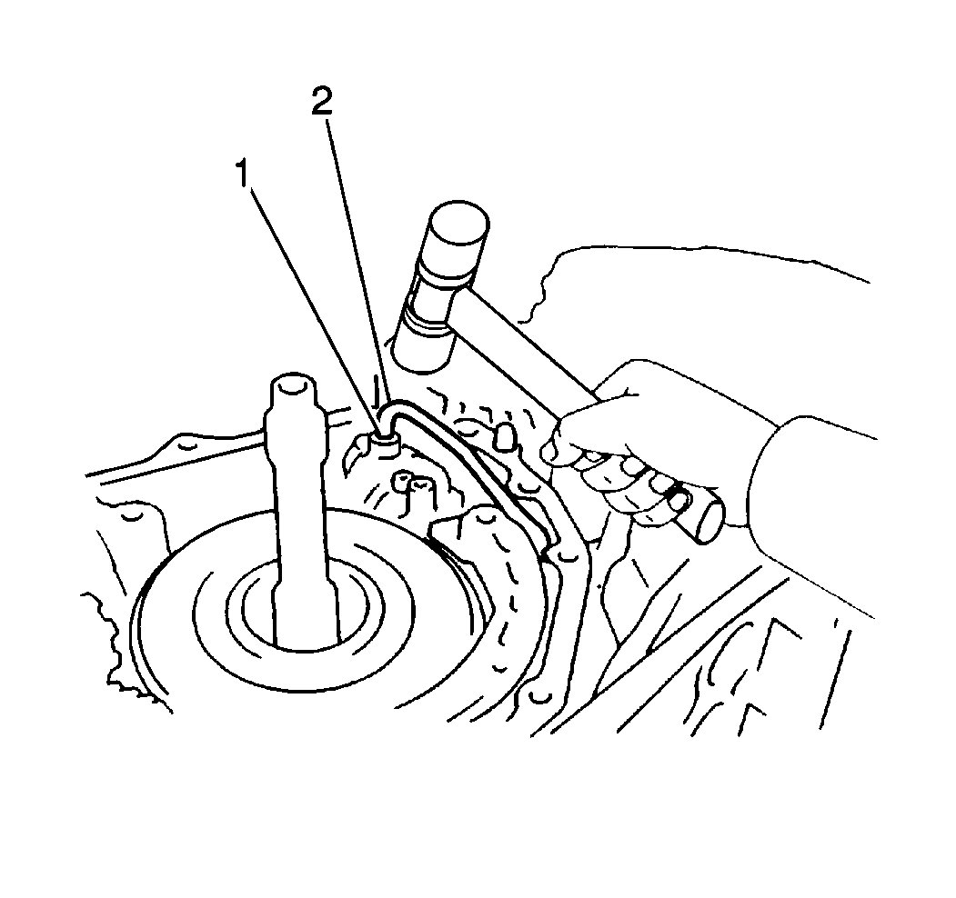
- Install the 2nd coast brake apply pipe (2) into the transaxle case.
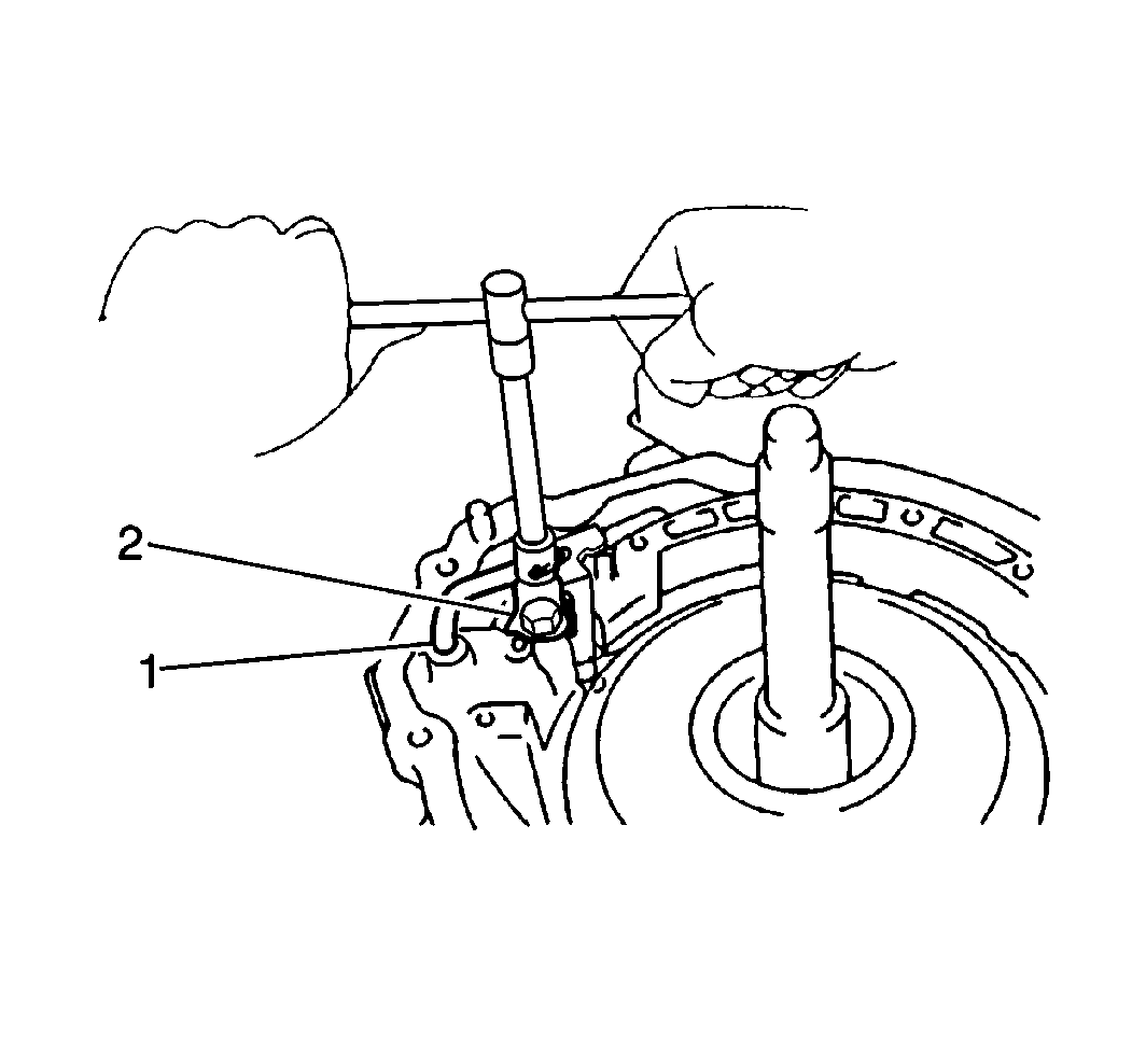
- Install the 2nd coast brake apply pipe bracket (2) into the transaxle case. Secure the pipe bracket with one bolt.
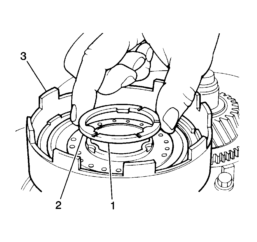
Important: During direct clutch thrust washer installation, verify that the oil grooves (brass surface) are facing toward the forward clutch.
Apply J 36850 (1) to the direct clutch thrust washer (2) in order to hold it in place on the direct clutch drum.
| • | Place a reference mark on the 2nd coast brake piston rod where the piston rod meets the transaxle case. |
| • | Apply 392 kPa to 785 kPa (57 psi to 114 psi) of compressed air into the 2nd coast brake apply passage. |
| • | Measure the distance between the reference mark and the transaxle case using a feeler gage to obtain the 2nd coast brake piston stroke. |
| • | Verify that the 2nd coast brake piston stroke falls within 1.5-3.5 mm (0.059-0.138 in). |
| • | If the 2nd coast brake piston stroke does not fall within specification, inspect the 2nd coast brake band for excessive wear or damage. |
Notice: Use the correct fastener in the correct location. Replacement fasteners must be the correct part number for that application. Fasteners requiring replacement or fasteners requiring the use of thread locking compound or sealant are identified in the service procedure. Do not use paints, lubricants, or corrosion inhibitors on fasteners or fastener joint surfaces unless specified. These coatings affect fastener torque and joint clamping force and may damage the fastener. Use the correct tightening sequence and specifications when installing fasteners in order to avoid damage to parts and systems.
Tighten
Tighten the 2nd coast brake apply pipe bracket bolt to 5 N·m
(44 lb in).
