Fuel Sender Assembly Replacement Rear Mounted - 15 Gal
Tools Required
J39765-A Fuel Sender Lock Ring Tool
Removal Procedure
- Remove the fuel tank. Refer to Fuel Tank Replacement .
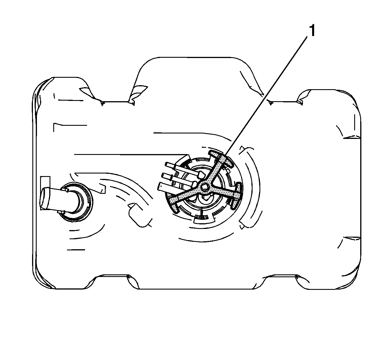
- Install the J39765-A (1), to the fuel sending unit lock ring.
- Using the J39765-A and a breaker bar, rotate the J39765-A counterclockwise disengaging the lock ring.
- Remove the J39765-A , and breaker bar.
- Remove the sending unit lock ring.
- Remove and discard the fuel sending unit O-ring seal.
- Slowly raise the sending unit until the fuel level sensor float arm is just visible.
- Tilt the module toward the fill tube on the fuel tank to allow the level sensor float arm to clear the tank opening. Remove the sending unit from the tank.
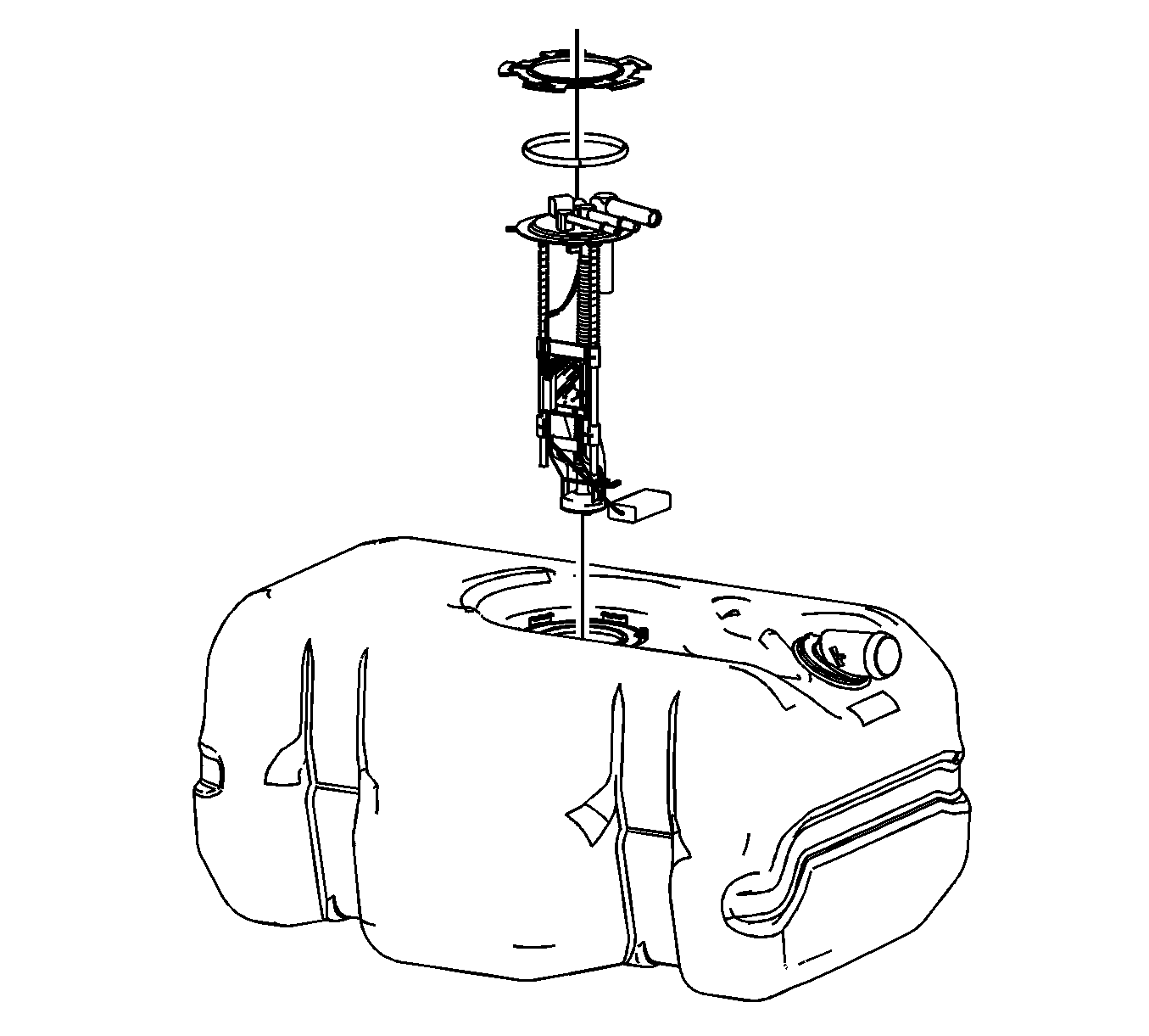
Notice: Do Not handle the fuel sender assembly by the fuel pipes. The amount of leverage generated by handling the fuel pipes could damage the joints.
Installation Procedure
- Tilt the module toward the fill tube on the fuel tank to allow the level sensor float arm to clear the tank opening. Install the sending unit into the tank.
- Lower sending unit assembly into the tank.
- Position a NEW fuel sending unit O-ring seal onto the sending unit.
- Position the sending unit lock ring onto the sending unit
- Install the J39765-A (1), to the fuel sending unit lock ring.
- Using the J39765-A and a breaker bar, rotate the J39765-A clockwise engaging the lock ring.
- Remove the J39765-A , and breaker bar.
- Install the fuel tank. Refer to Fuel Tank Replacement .


Fuel Sender Assembly Replacement Mid Mounted
Tools Required
J 44402 Fuel Tank Sending Unit Wrench
Removal Procedure
- Remove the fuel tank. Refer to Fuel Tank Replacement .
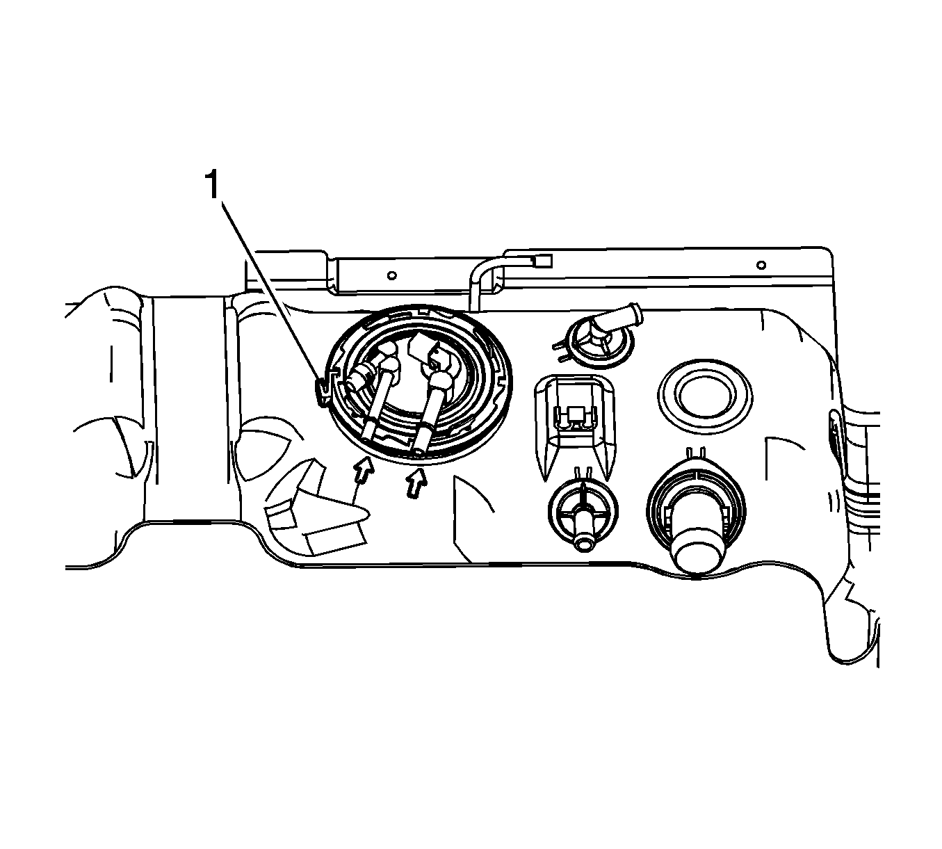
- Disengage the fuel tank lock ring retainer (1).
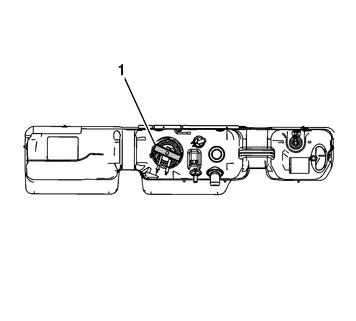
- Install the J 44402 (1), to the fuel sending unit lock ring.
- Using the J 44402 and a breaker bar, rotate the J 44402 counterclockwise disengaging the lock ring.
- Remove the J 44402 , and breaker bar.
- Remove the sending unit lock ring.
- Slowly raise the sending unit until the fuel level sensor float arm is just visible.
- Tilt the module toward the rear of the fuel tank to allow the level sensor float arm to clear the tank opening. Remove the sending unit from the tank.
- Remove and discard the fuel sending unit seal.
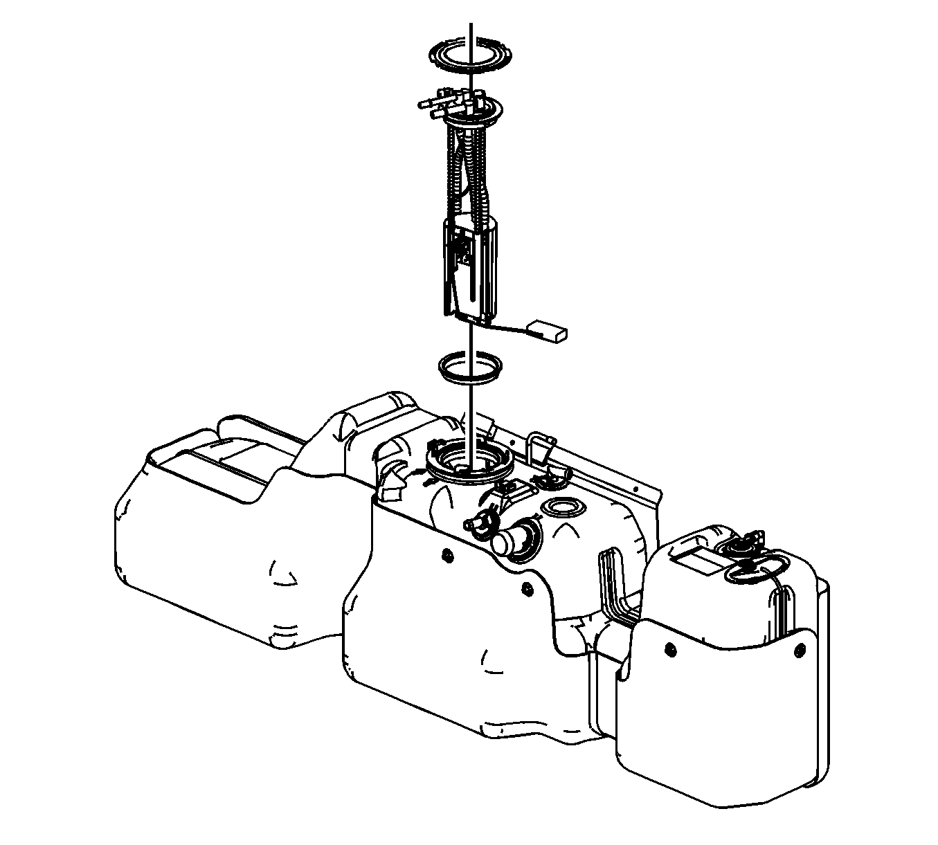
Notice: Do Not handle the fuel sender assembly by the fuel pipes. The amount of leverage generated by handling the fuel pipes could damage the joints.
Important: When removing the sending unit from the fuel tank, be aware that the module reservoir bucket is full of fuel. The module must be tipped slightly during removal to avoid bending the fuel level sensor float arm.
Installation Procedure
- Install a NEW fuel sending unit seal to the fuel tank.
- Tilt the module toward the rear of the fuel tank to allow the level sensor float arm to clear the tank opening. Install the sending unit to the tank.
- Lower the sending unit into the fuel tank.
- Position and install the sending unit lock ring.
- Install the J 44402 (1), to the fuel sending unit lock ring.
- Using the J 44402 and a breaker bar, rotate the J 44402 clockwise engaging the lock ring.
- Remove the J 44402 , and breaker bar.
- Ensure that the fuel tank lock ring retainer (1) is completely engaged to the lock ring.
- Install the fuel tank. Refer to Fuel Tank Replacement .

Important: The bucket must be tipped slightly during installation to avoid bending the fuel level sensor float arm.


Fuel Sender Assembly Replacement Rear Mounted
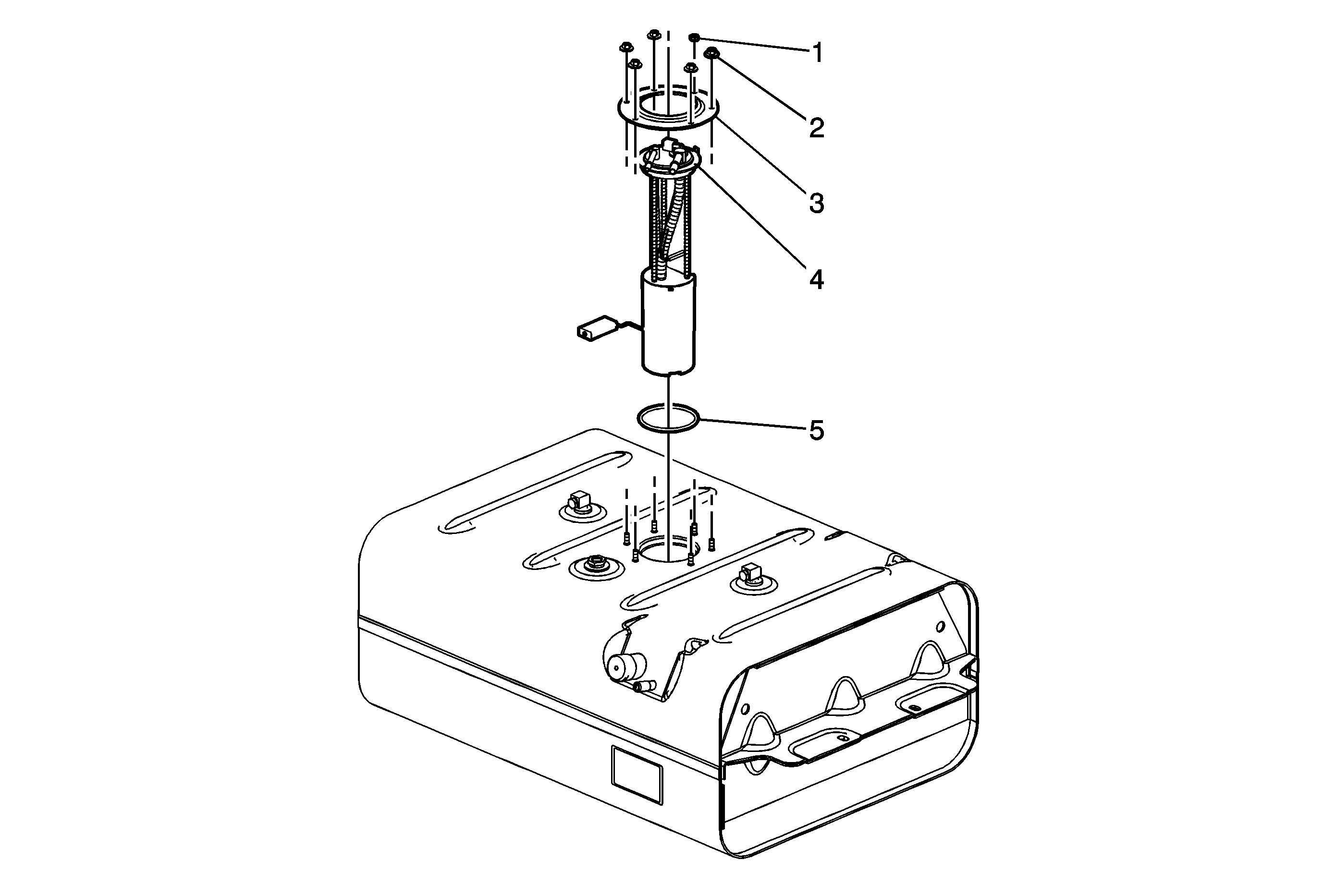
Callout | Component Name | ||||
|---|---|---|---|---|---|
Preliminary ProcedureRemove the fuel tank. Refer to Fuel Tank Replacement . | |||||
1 | Fuel Tank Ground Strap Nut (Qty: 1) Notice: Refer to Fastener Notice in the Preface section. Tighten | ||||
2 | Fuel Sender Ring Nut (Qty: 5) Tighten | ||||
3 | Fuel Sender Retaining Ring | ||||
4 | Fuel Tank Fuel Pump Module Notice: Do Not handle the fuel sender assembly by the fuel pipes. The amount of leverage generated by handling the fuel pipes could damage the joints. Tip
| ||||
5 | Fuel Sender Seal Tip | ||||
Fuel Sender Assembly Replacement Side Mounted
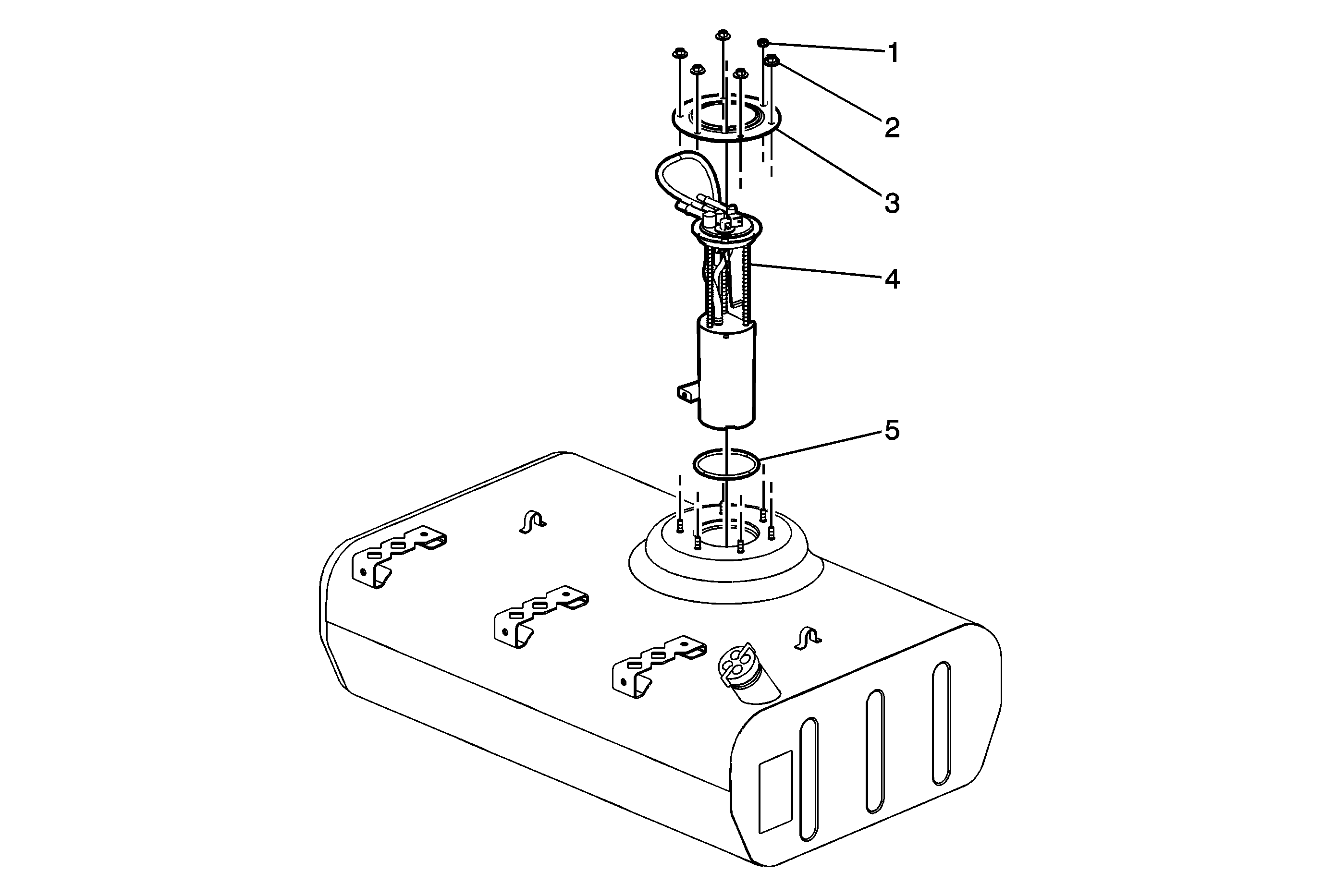
Callout | Component Name | ||||
|---|---|---|---|---|---|
Preliminary ProcedureRemove the fuel tank. Refer to Fuel Tank Replacement . | |||||
1 | Fuel Tank Ground Strap Nut (Qty: 1) Notice: Refer to Fastener Notice in the Preface section. Tighten | ||||
2 | Fuel Sender Ring Nut (Qty: 5) Tighten | ||||
3 | Fuel Sender Retaining Ring | ||||
4 | Fuel Tank Fuel Pump Module Notice: Do Not handle the fuel sender assembly by the fuel pipes. The amount of leverage generated by handling the fuel pipes could damage the joints. Tip
| ||||
5 | Fuel Sender Seal Tip | ||||
