Valve Rocker Arm Cover Replacement - Upper Left Side LBZ, LLY
Removal Procedure
- Remove the engine cover. Refer to Engine Cover Replacement .
- Remove the air cleaner. Refer to Air Cleaner Replacement .
- Drain the cooling system. Refer to Cooling System Draining and Filling .
- Disconnect the negative battery cable. Refer to Battery Negative Cable Disconnection and Connection .
- Remove the fuel injectors. Refer to Fuel Injector Replacement .
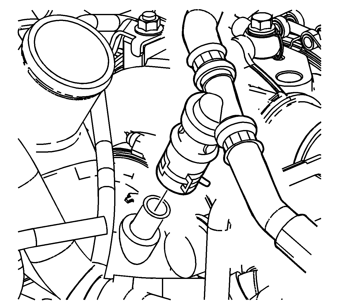
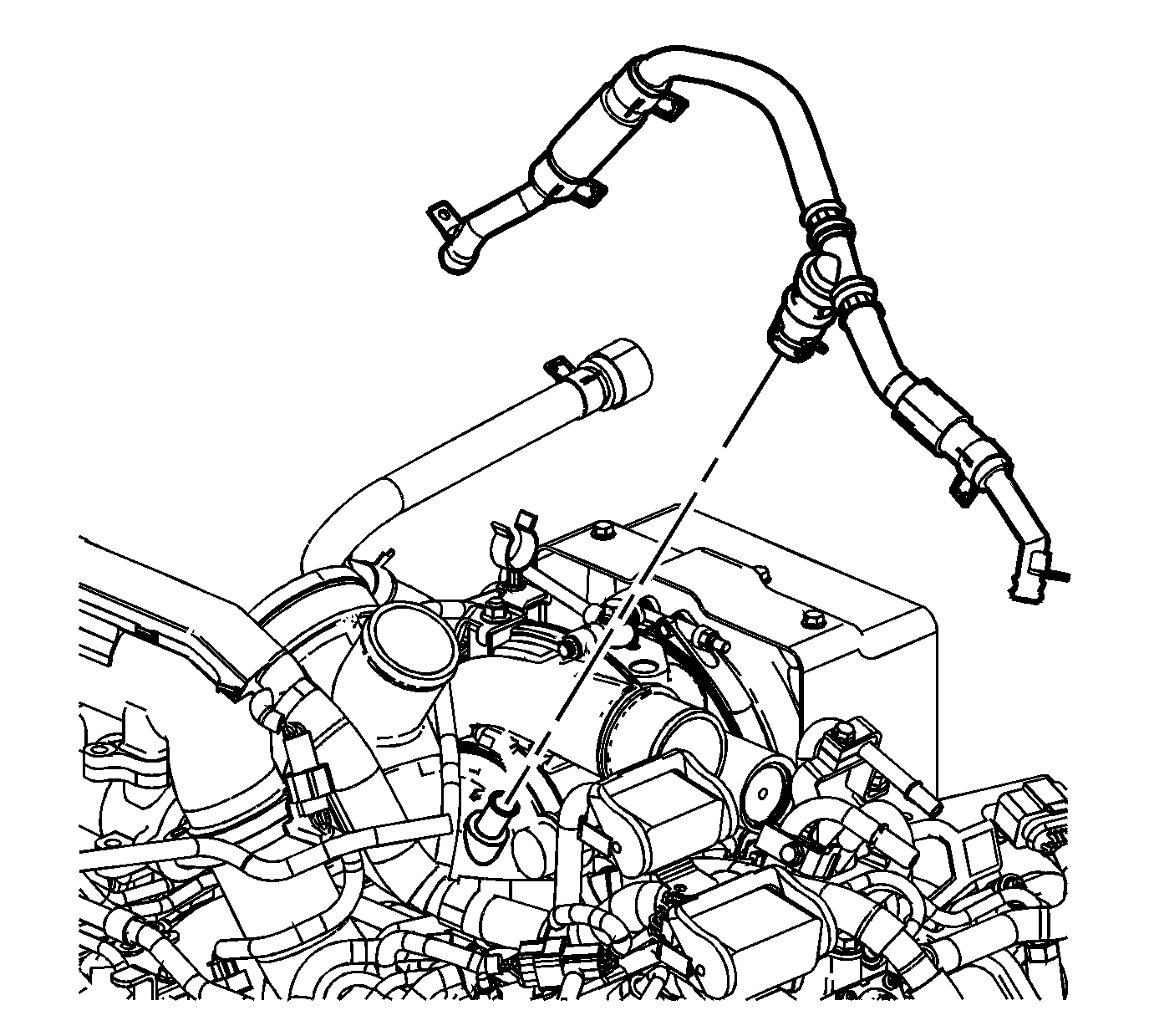
- Loosen the charged air cooler inlet duct connector to turbocharger clamp (1).
- Remove the charged air cooler inlet duct connector (4) from the turbocharger.
- Remove the battery cable to generator nut.
- If equipped, remove the auxiliary generator. Refer to Auxiliary Generator Replacement .
- Remove the battery cable harness clip from the bracket.
- Remove the battery cable junction block bolt from the power steering pump.
- Move and secure the battery cables out of the way.
- Disconnect the fuel lines. Refer to Metal Collar Quick Connect Fitting Service .
- Remove the fuel hose bracket nut.
- Remove the fuel filter/heater element housing. Refer to Fuel Filter Assembly Replacement .
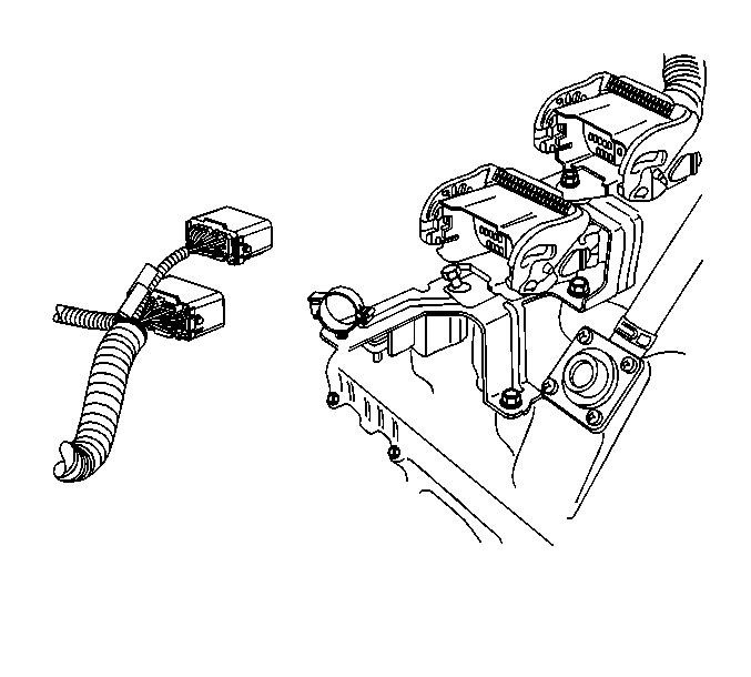
- Disconnect the main engine electrical harness connectors. Lift up on the latches in order to disconnect the connectors.
- Remove the main engine electrical harness from the clip on the bracket.
- Disconnect the barometric pressure sensor electrical connector.
- Remove the main engine electrical harness connector hold down bolts.
- Remove the main electrical connector harness bracket bolts.
- Remove the main electrical connector harness bracket.
- Remove the water outlet tube. Refer to Water Outlet Tube Replacement .
- Remove the auxiliary generator, if equipped. Refer to Auxiliary Generator Replacement .
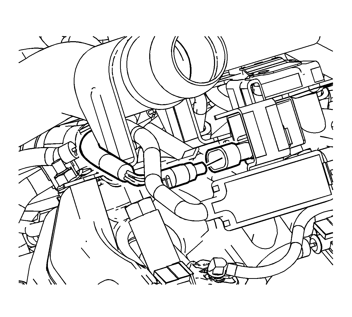
- Reposition the left positive crankcase ventilation (PCV) hose clamp at the resonator tee.
- Remove the left PCV hose from the tee.
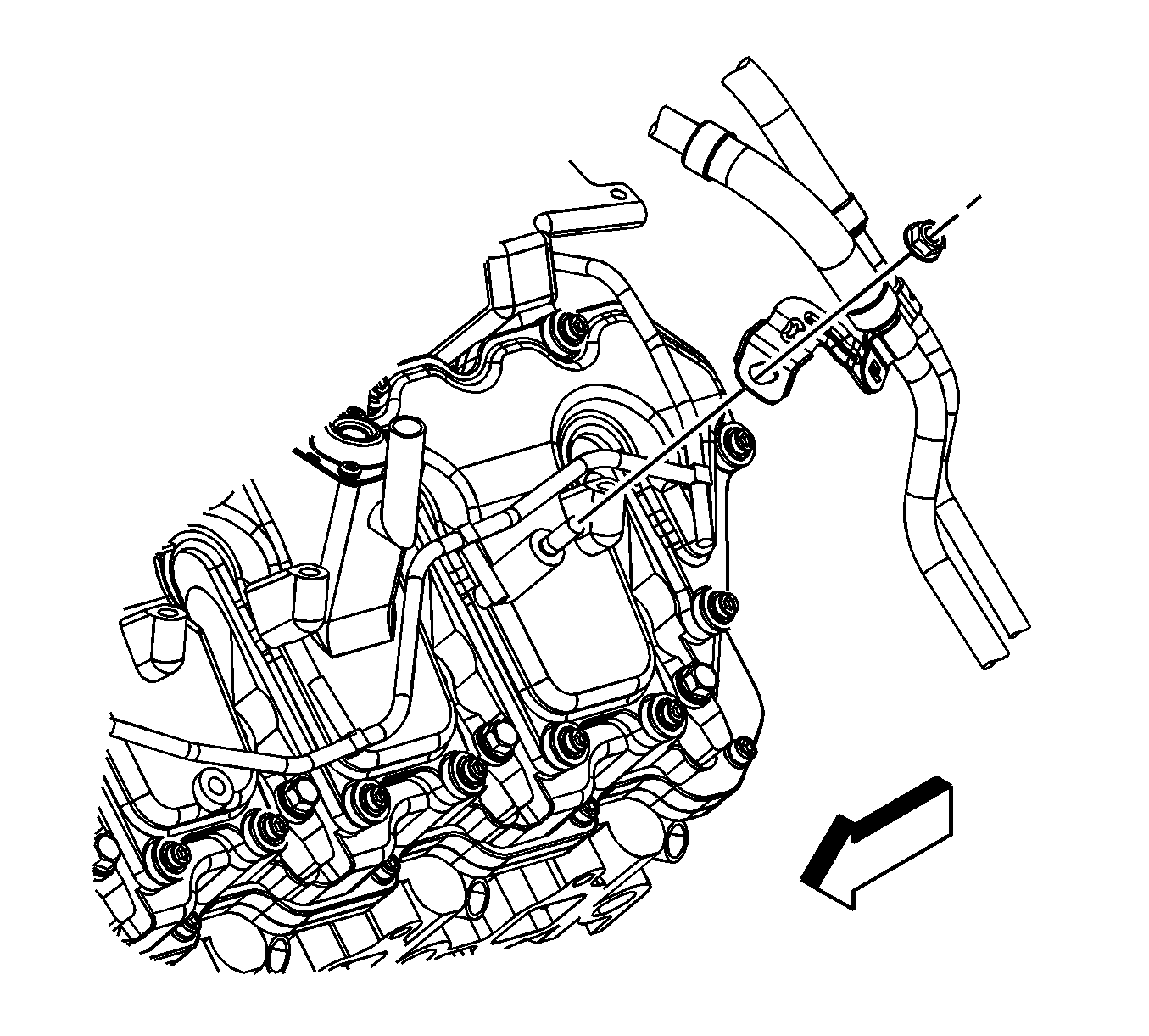
- Remove the left PCV pipe bolt.
- Remove the left PCV pipe.
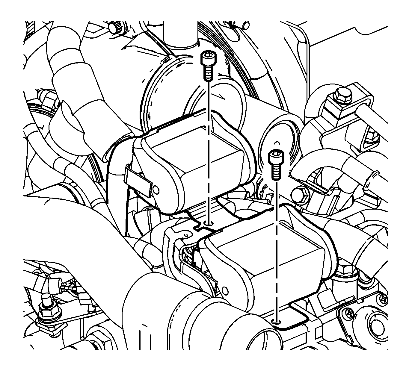
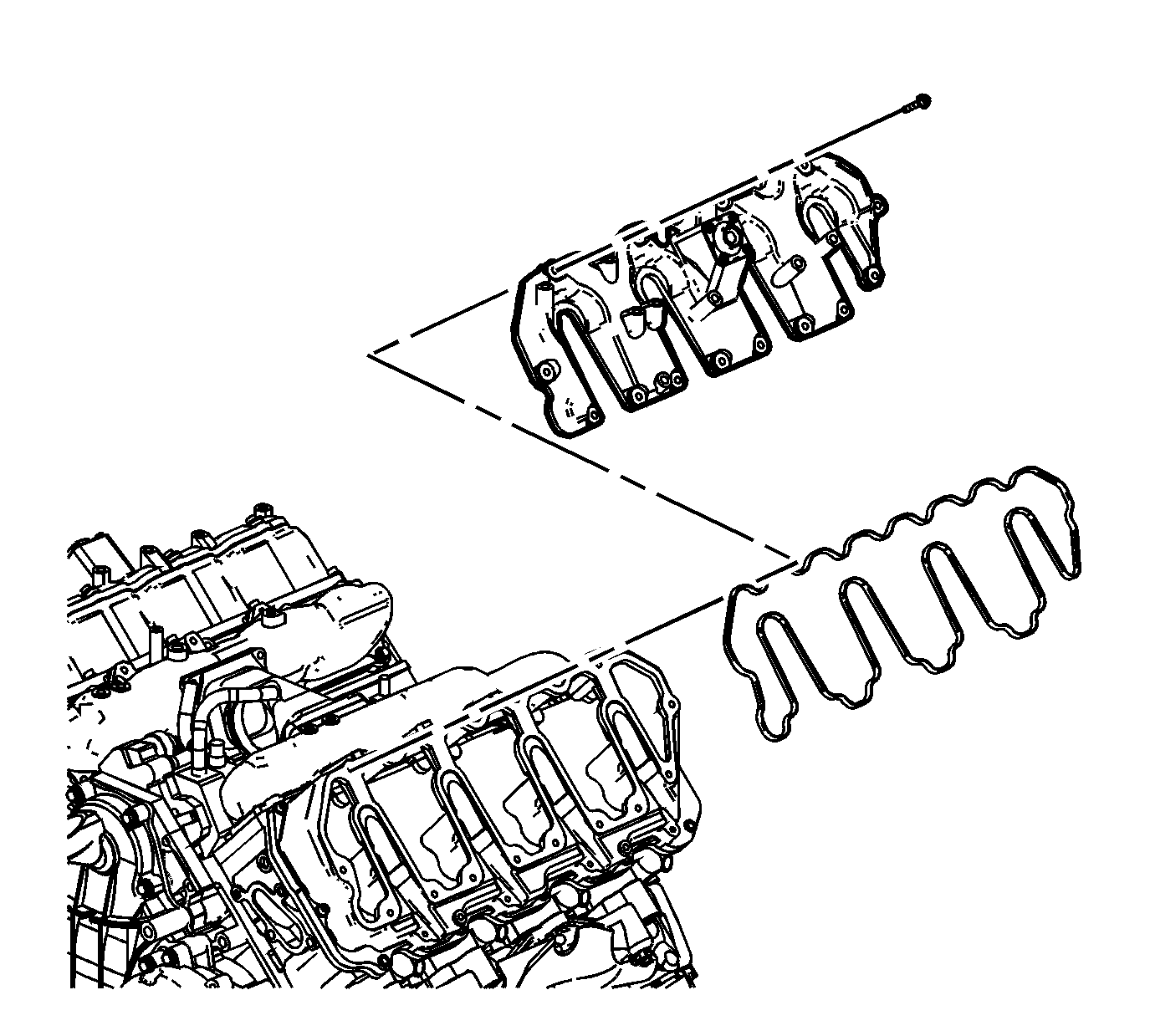
- Remove the upper valve rocker arm cover bolts.
- Remove the upper valve rocker arm cover.
- Remove and discard the upper valve rocker arm cover gasket.
- If required, clean and inspect the upper valve rocker arm cover. Refer to Valve Rocker Arm Cover Cleaning and Inspection - Upper .
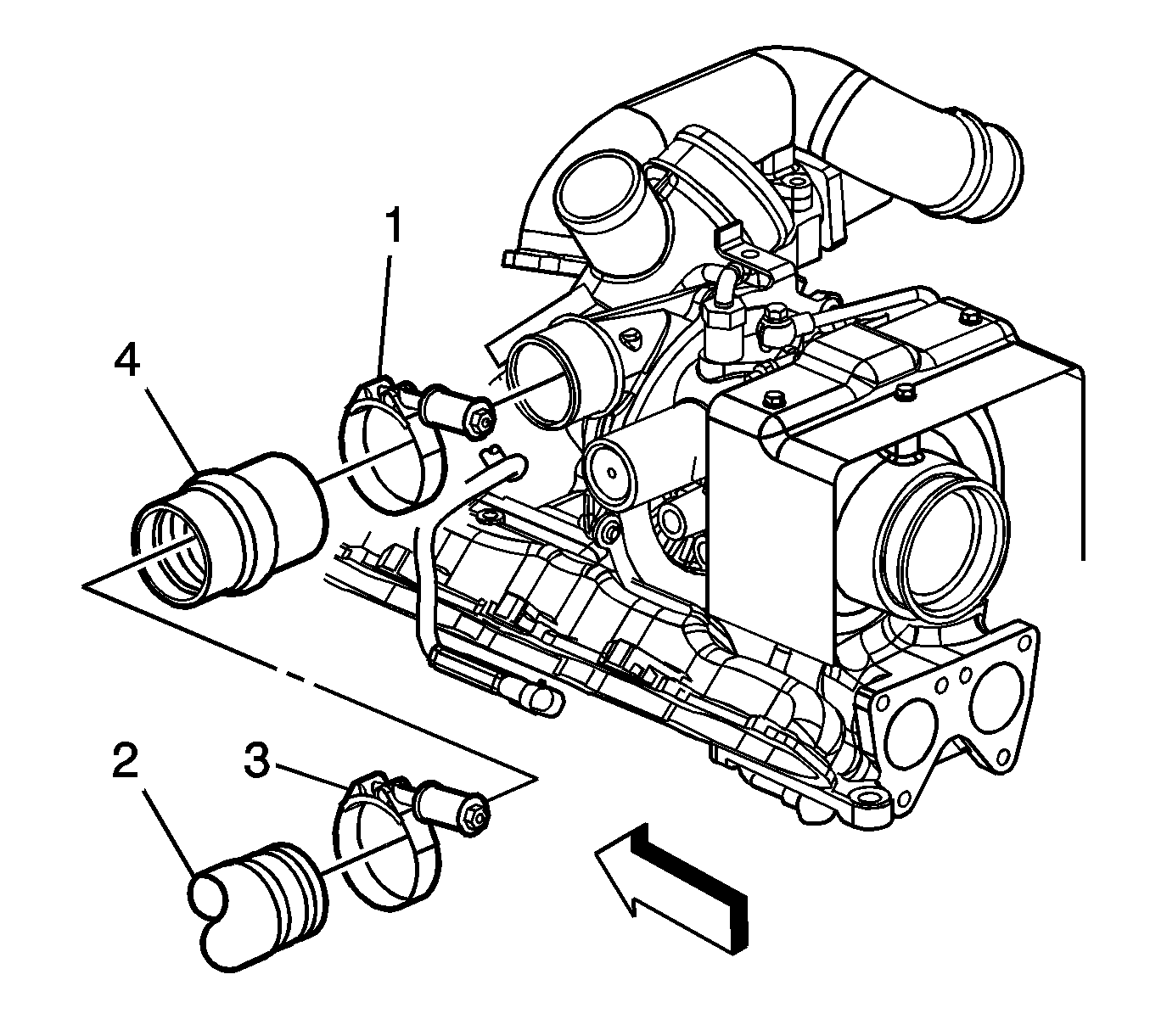
Important: After removing the charged air cooler duct, cover the turbocharger opening with tape in order to prevent entry of objects.
Important: Do not use a screwdriver or other tool to pry the hose loose. The hose can be torn or damaged. Loosen the hose by twisting.
Installation Procedure
- Inspect the valve rocker arm cover gasket for damage. If the valve rocker arm cover gasket is not damaged, reuse the gasket.
- Install the valve rocker arm cover gasket.
- Install the upper valve rocker arm cover.
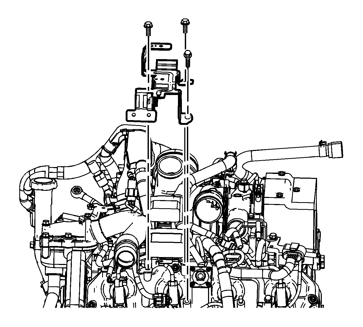
- Install the upper valve rocker arm cover bolts.
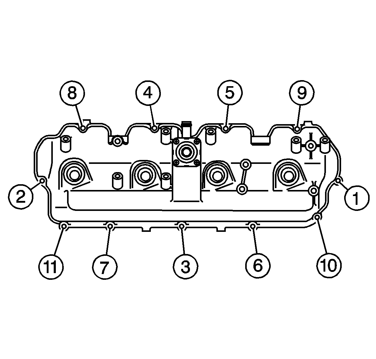
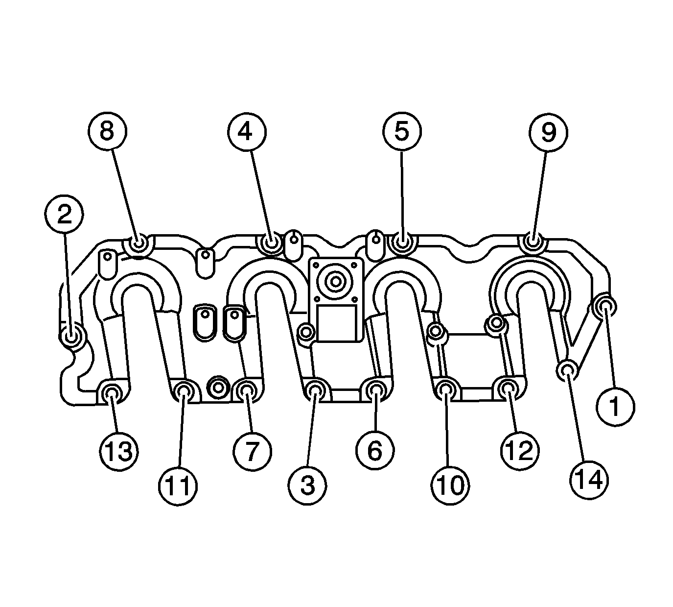
- Tighten the upper valve rocker arm cover bolts in the sequence shown.
- Install the fuel injectors. Refer to Fuel Injector Replacement .
- Install the left PCV pipe.
- Install the left PCV pipe bolt.
- Install the left PCV hose to the tee.
- Position the left PCV hose clamp at the resonator tee.
- Install the water outlet tube. Refer to Water Outlet Tube Replacement .
- Install the auxiliary generator, if equipped. Refer to Auxiliary Generator Replacement .
- Install the main electrical connector harness bracket.
- Install the main electrical connector harness bracket bolts.
- Install the main engine electrical harness connector hold down bolts.
- Connect the barometric pressure sensor electrical connector.
- Connect the main engine electrical harness connectors.
- Install the main engine electrical harness to the clip on the bracket.
- Connect the fuel lines. Refer to Metal Collar Quick Connect Fitting Service .
- Install the fuel hose bracket nut.
- Position the generator positive cable.
- Install the generator positive cable in the clip on the engine front cover.
- Install the generator positive cable and nut.
- Install the fuel filter/heater element housing. Refer to Fuel Filter Assembly Replacement .
- Remove the tape from the turbocharger openings.
- Install the charged air cooler inlet duct connector (4) to the turbocharger.
- Tighten the charged air cooler inlet duct connector to turbocharger clamp (1).
- Install the air cleaner. Refer to Air Cleaner Replacement .
- Install the engine cover. Refer to Engine Cover Replacement .
- Fill the cooling system. Refer to Cooling System Draining and Filling .
- Connect the negative battery cable. Refer to Battery Negative Cable Disconnection and Connection .
Notice: Refer to Fastener Notice in the Preface section.
Tighten
Tighten the bolts to 8 N·m (71 lb in).
Tighten
Tighten the bolt to 18 N·m (13 lb ft).
Tighten
Tighten the bolt to 21 N·m (15 lb ft).
Tighten
Tighten the bolt to 10 N·m (89 lb in).
Tighten
Tighten the nut to 21 N·m (15 lb ft).
Tighten
Tighten the nut to 9 N·m (80 lb in).
Important: Lubricate the end of the duct prior to installation.
Tighten
Tighten the clamp to 6 N·m (53 lb in).
Valve Rocker Arm Cover Replacement - Upper Left Side LMM
Tools Required
J-46594 Fuel Injector Puller
Removal Procedure
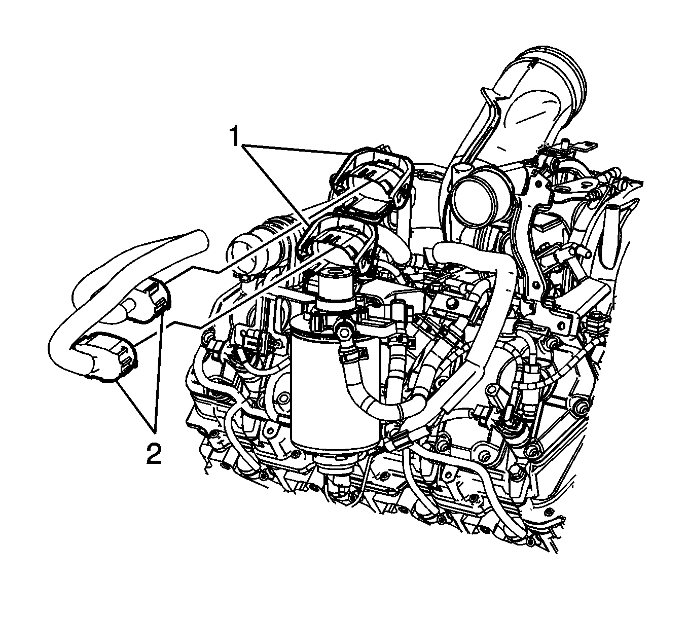
- Rotate the electrical connector lever locks (1) rearward.
- Disconnect the vehicle's engine wiring harness main electrical connectors (2) from the engine wiring harness main electrical connectors.
- Disconnect the negative battery cables. Refer to Battery Negative Cable Disconnection and Connection .
- Remove the fuel filter assembly. Refer to Fuel Filter Replacement
- Remove the fuel feed pipes. Refer to Fuel Feed Pipe Replacement
- Remove the injector pipes. Refer to Fuel Injection Fuel Return Pipe Replacement - Left Side
- Remove the water outlet tube. Refer to Water Outlet Tube Replacement
- Remove the positive crankcase ventilation (PCV) hose/pipe. Refer to Positive Crankcase Ventilation Hose/Pipe/Tube Replacement .
- Remove the auxiliary generator, if equipped. Refer to Auxiliary Generator Replacement .
- Remove the oil filler tube. Refer to Oil Filler Tube Replacement
- Remove the upper valve rocker arm cover bolts.
- Remove the upper valve rocker arm cover.
- Remove the upper valve rocker arm cover gasket.
- Inspect the upper valve rocker arm cover gasket for damage, replace if necessary. Otherwise reuse the old gasket.
Installation Procedure
- Install the valve rocker arm cover gasket.
- Install the upper valve rocker arm cover.
- Install the upper valve rocker arm cover bolts.
- Tighten the upper valve rocker arm cover bolts.
- Install the oil filler tube. Refer to Oil Filler Tube Replacement
- Install the auxiliary generator, if equipped. Refer to Auxiliary Generator Replacement .
- Install the positive crankcase ventilation (PCV) hose/pipe. Refer to Positive Crankcase Ventilation Hose/Pipe/Tube Replacement
- Install the water outlet tube. Refer to Water Outlet Tube Replacement
- Install the injector pipes. Refer to Fuel Injection Fuel Return Pipe Replacement - Left Side
- Install the fuel feed pipes. Refer to Fuel Feed Pipe Replacement
- Install the fuel filter assembly. Refer to Fuel Filter Replacement
- Connect the negative battery cables. Refer to Battery Negative Cable Disconnection and Connection .
- Rotate the electrical connector lever locks (1) rearward.
- Disconnect the vehicle's engine wiring harness main electrical connectors (2) from the engine wiring harness main electrical connectors.
Notice: Refer to Fastener Notice in the Preface section.
Tighten
Tighten the bolts in the sequence shown to 8 N·m (71 lb in).
