Tools Required
| • | J 44640 Valve Stem Seal Installer |
Removal Procedure

- Remove the valve rocker arm shaft, valve bridges,
and pushrods for the cylinder head being serviced. Refer to
Valve Rocker Arm, Shaft, and Push Rod Replacement
.
- Remove the glow plug for the cylinder requiring service. Refer to
Glow Plug Replacement - Bank 1
or
Glow Plug Replacement - Bank 2
.
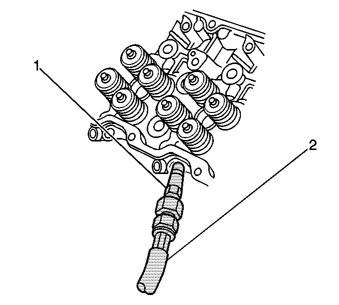
- In order to apply shop air to the cylinders use the following procedures
to modify J 26999-20
(1) and J 26999
(2):
| 3.1. | Remove the valve core from J 26999-20
to allow air to flow. |
| 3.2. | Remove the quick connect fitting from J 26999
. |
| 3.3. | Adapt the quick connect fitting in order to use for shop air. |
| 3.4. | Connect the quick connect fitting to J 26999-20
. |
Important: Rotate the cylinder to be serviced to the bottom of the stroke. This is to
ensure that the engine does not rotate when the compressed air is applied to the cylinder
being serviced.
- Install J 26999-20
into the glow plug hole
for the cylinder being serviced.
- Apply compressed air to hold the valves in place. If the compressed air
is released, the valves can drop into the cylinder.

Caution: Compressed valve springs have high tension against the valve spring
compressor. Valve springs that are not properly compressed by or released
from the valve spring compressor can be ejected from the valve spring compressor
with intense force. Use care when compressing or releasing the valve spring
with the valve spring compressor and when removing or installing the valve
stem keys. Failing to use care may cause personal injury.
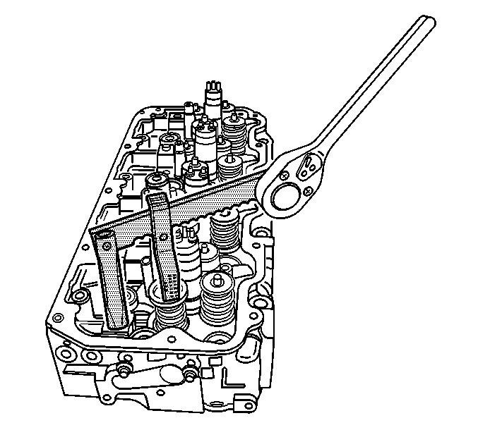
- Install J 44646
to the rocker arm bosses on the cylinder head.
J 44646 should be installed in the rocker
arm boss next to the cylinder being serviced. The pivot pin can be removed from the
stand to allow the stand to be installed. The lever has different locating holes for
the pivot pin depending on available clearance. The lever is also notched for different
locations of the compressor.
- Using J 44646
compress the valve
spring.

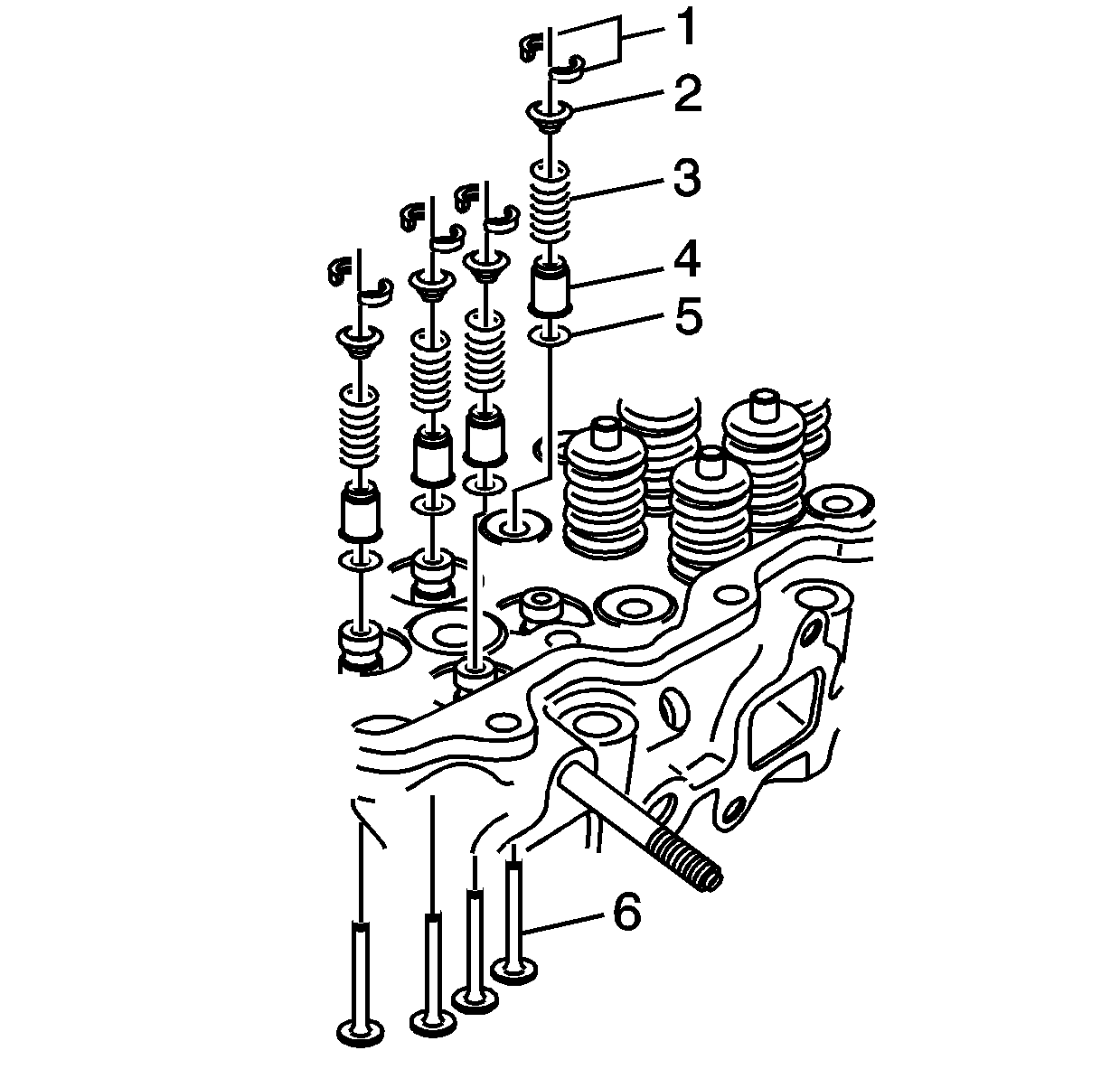
- Remove the valve keys (1) from the valve stem.
- Carefully release the valve spring tension.
- Remove the valve spring upper seat (2) and the valve spring (3).
- Remove the valve stem oil seal (4).
- Remove the valve spring lower seat (5).
- Continue removing the remaining valve stem seals for the cylinder using
the above procedure.
Installation Procedure

Notice: Air pressure should remain applied to the cylinder for installation.
- Install the valve
spring lower seat.
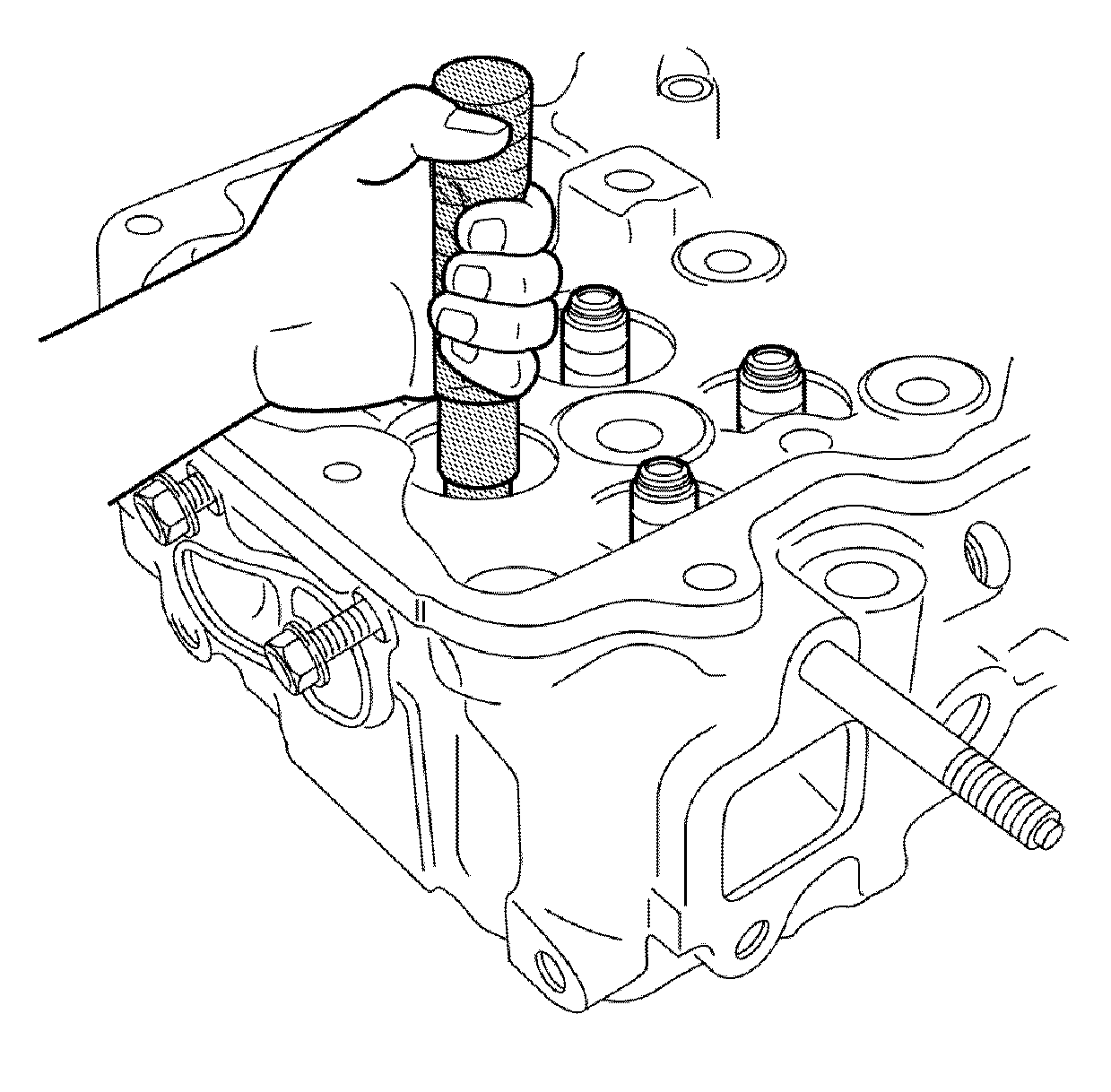
- Install the valve stem seal using J 44640
.

- Install the valve spring (3), the painted
end of the valve spring goes toward the cylinder head.
- Install the valve spring upper seat (2).

Caution: Compressed valve springs have high tension against the valve spring
compressor. Valve springs that are not properly compressed by or released
from the valve spring compressor can be ejected from the valve spring compressor
with intense force. Use care when compressing or releasing the valve spring
with the valve spring compressor and when removing or installing the valve
stem keys. Failing to use care may cause personal injury.
- Using J 44646
compress the valve spring.
- Install the valve keys to the valve stem.
Notice: The valve stem keys must correctly seat in the valve spring cap. Engine
damage may occur by not installing properly.
- Carefully release the valve spring pressure.
Make sure the valve keys stay in place.
- Continue to install the 3 remaining valve stem seals for the cylinder.

- Release the compressed air holding the valves
in place.
- Remove J 26999-20
(1) from
the glow plug hole.
- Continue to replace the valve stem seals on the remaining cylinders using
the above procedures.
- Install the glow plug. Refer to
Glow Plug Replacement - Bank 1
or
Glow Plug Replacement - Bank 2
.
- Install the valve rocker arm shaft, the valve bridges, and the push rods.
Refer to
Valve Rocker Arm, Shaft, and Push Rod Replacement
.


