Fuel Injector Replacement Left
Special Tools
| • | EN-47909 Injector Bore and Sleeve Cleaning Kit |
| • | J-46594 Fuel Injector Puller |
Removal Procedure
- Remove the left side fuel injection fuel feed pipes. Refer to Fuel Injection Fuel Feed Pipe Replacement - Left Side .
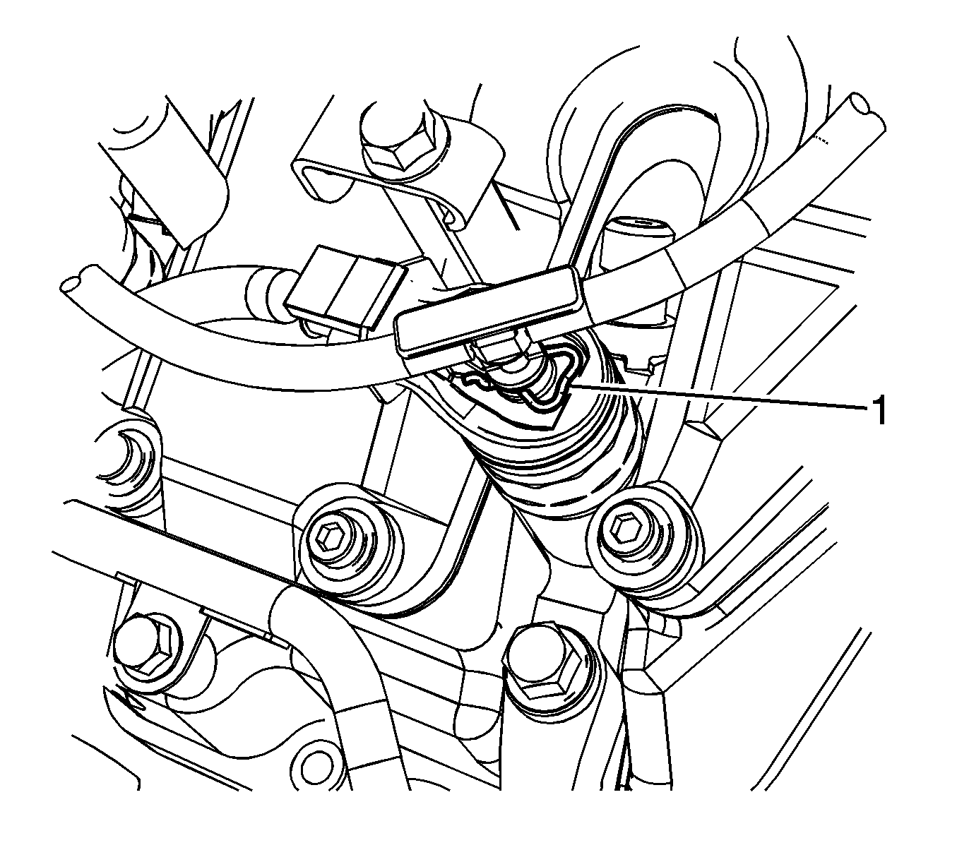
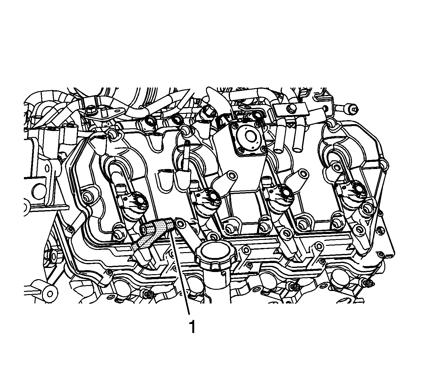
- Remove the fuel return hose clips (1).
- Disconnect the fuel return hose from the fuel injectors.
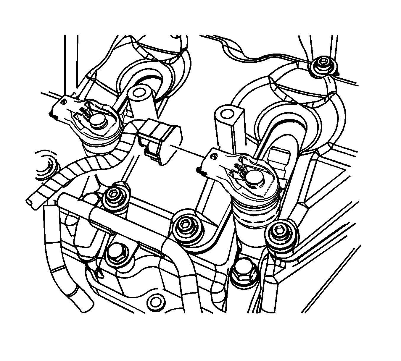
- Disconnect the engine wiring harness electrical connectors from the fuel injector(s).
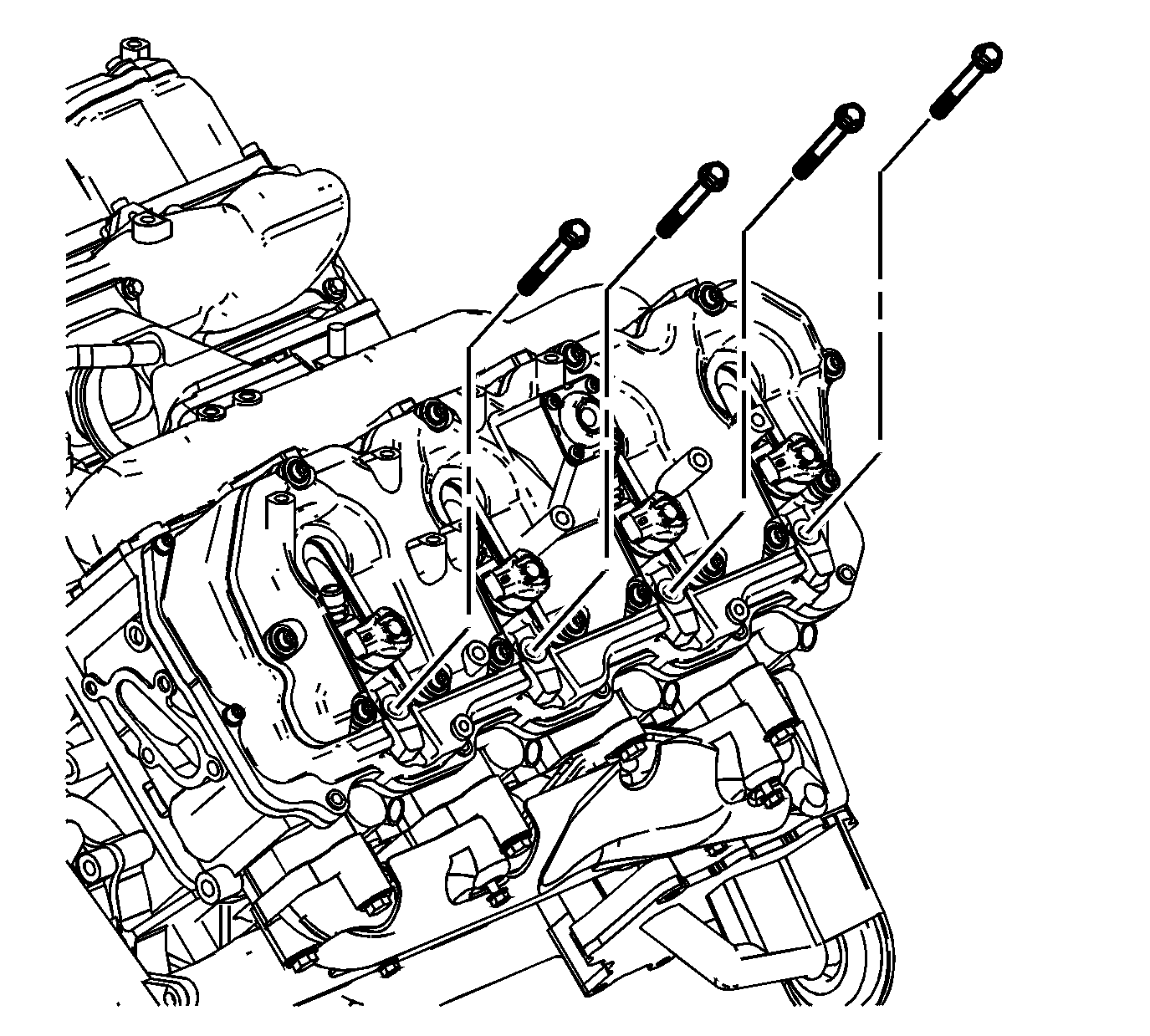
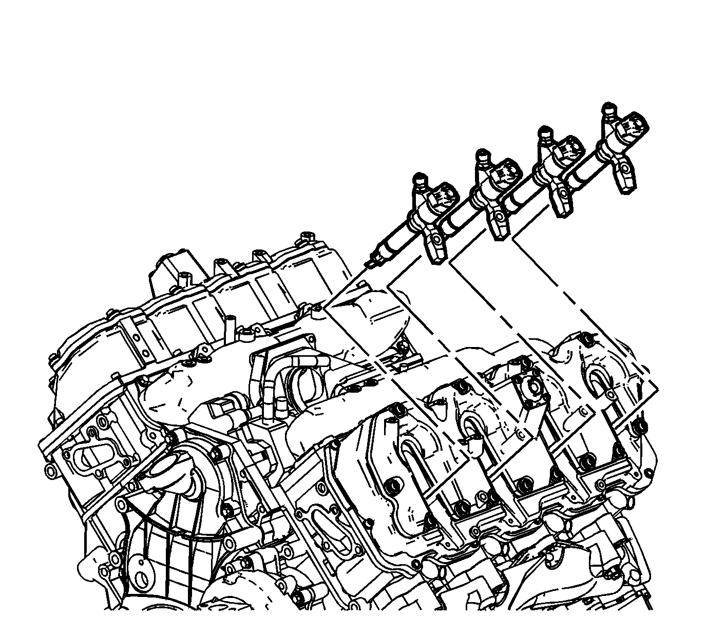
- Remove the fuel injector bracket bolts.
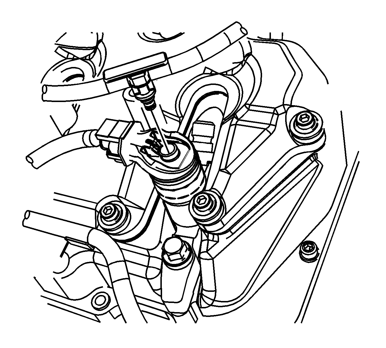
- Install the J-46594 (1) into the bolt hole in the fuel injector bracket.
- Install a flare nut wrench onto the J-46594 and pull back away from the fuel injector, until the injector releases from its seat.
- Remove the J-46594 .
- Remove the fuel injectors and brackets.
- If necessary, remove the fuel injector bracket pins.
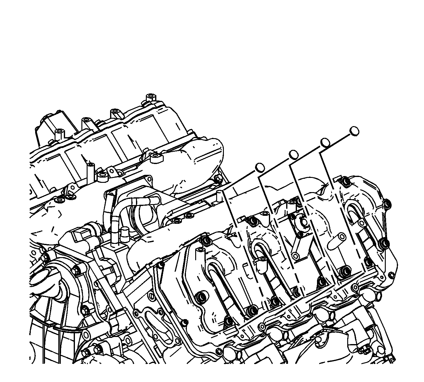
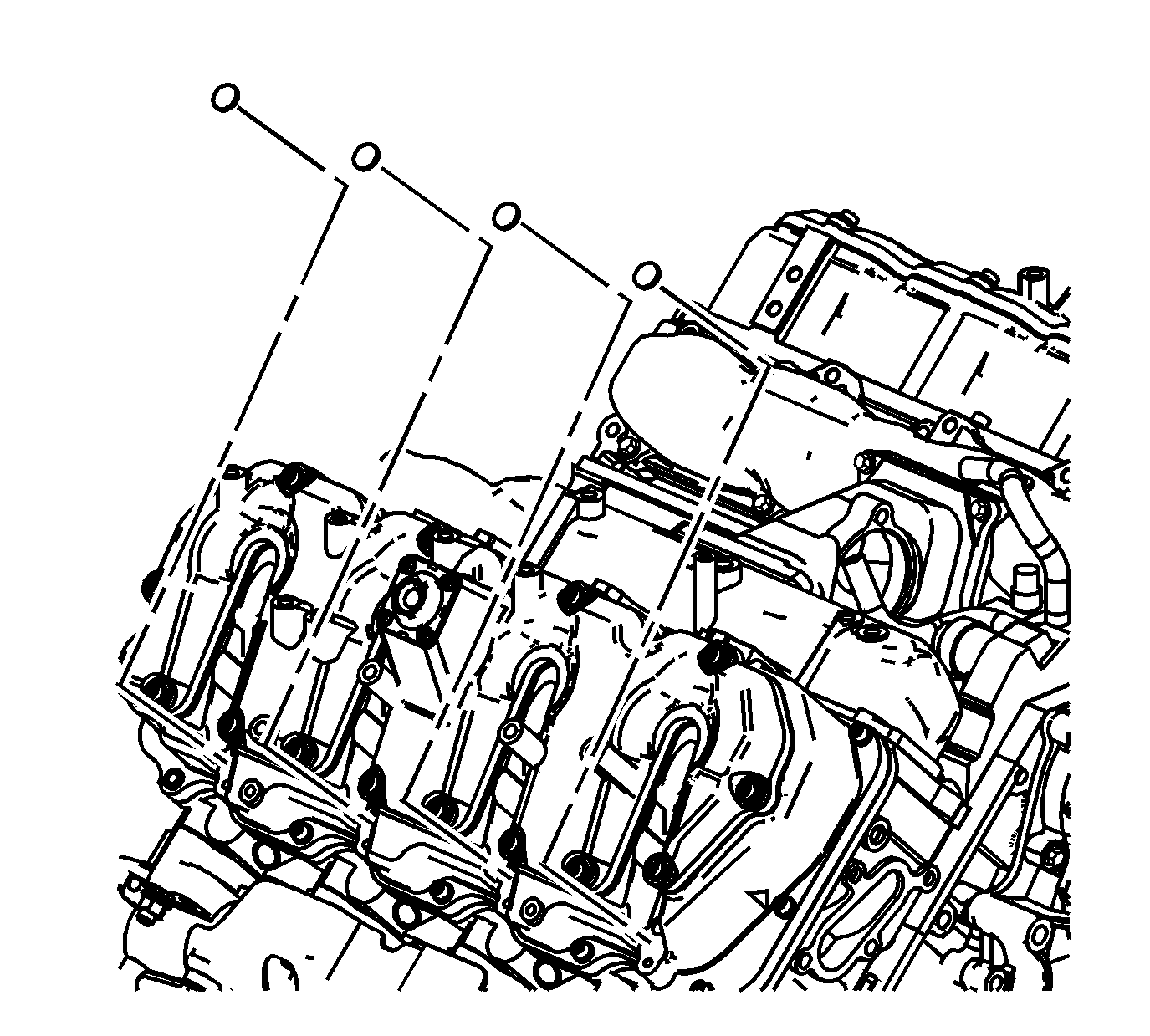
- Remove and discard the copper washer from the fuel injector bore.
- Remove and discard the O-ring from the fuel injector.
Fuel Injector Cleaning and Inspection
Important: If reusing the old injectors perform the following:
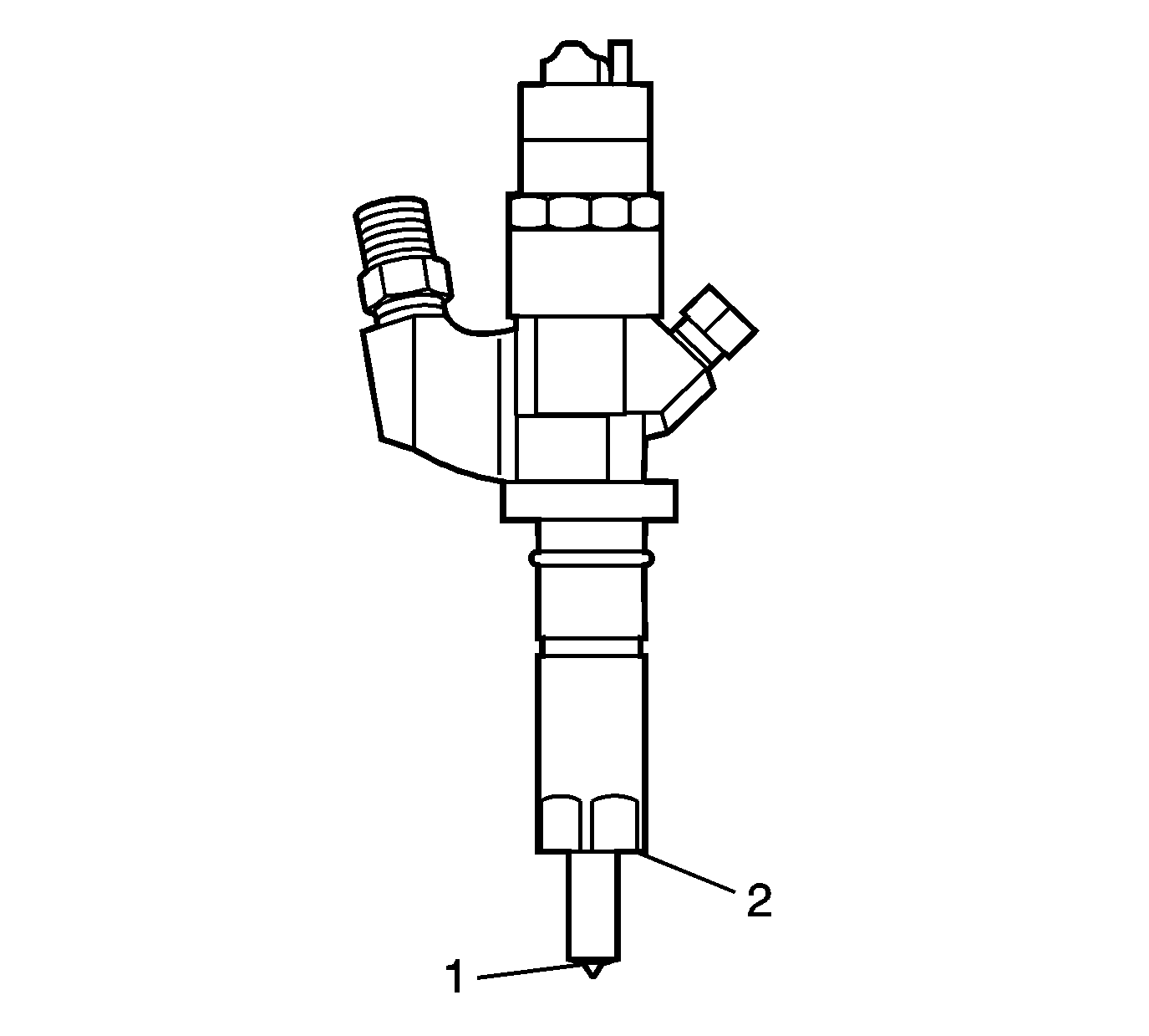
- Use a soft bristle non-metallic brush and Top Engine Cleaner, GM P/N 1052626 or equivalent, to remove any deposits from the nozzle tip (1) and the copper washer sealing area (2) before re-installation.
- Inspect the fuel injector nozzle tip (1) for any signs of discoloration (dark yellow, tan or blue) due to excessive heat.
- Replace the injector if any damage is found.
- Clean the fuel injector high pressure line.
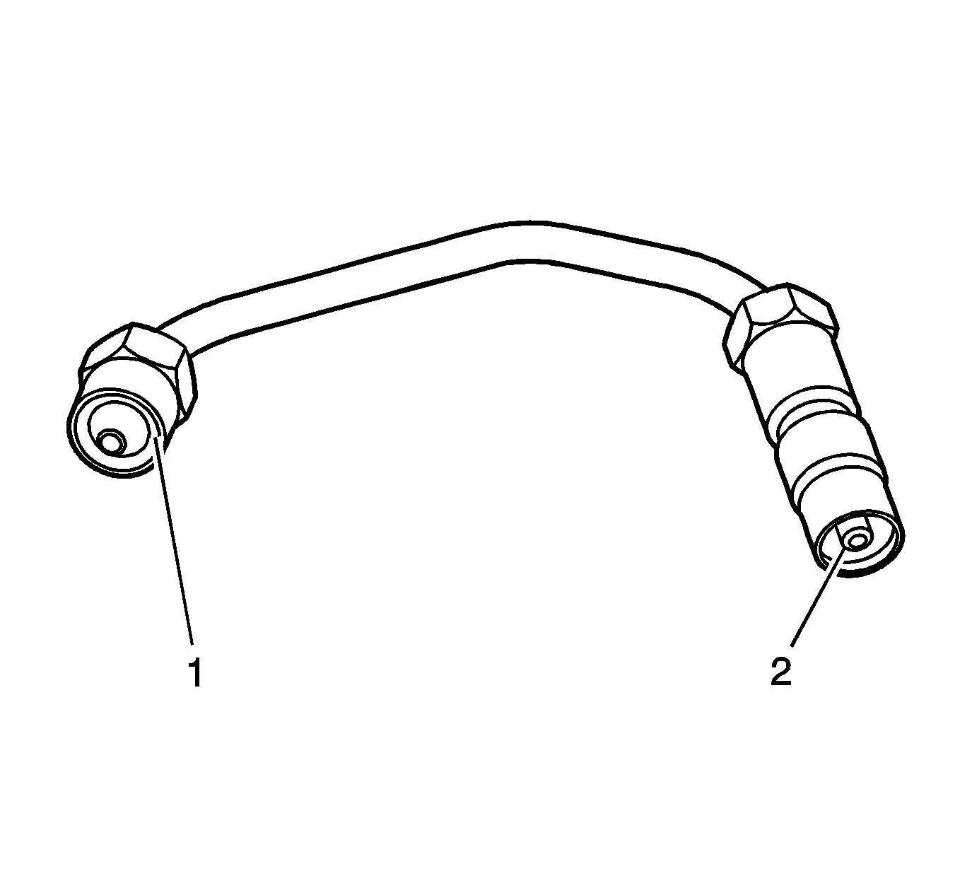
- Inspect the fuel injector line for excessive corrosion or damage to the sealing surfaces (1, 2). Replace the line if any damage is found.
Injector Bore Cleaning
Important: The procedure below will aid in the cleaning of carbon deposits from the injector sleeve during an injector replacement
- Install the EN-47909-2 Radial Brush (brass), to the EN-47909-1 Handle Assembly.
- Insert the brush into the injector bore and rotate the handle in order to break loose any carbon deposits from the injector bore walls and the combustion deck hole.
- Using compressed air, evacuate any debris from the injector bore.
- Remove the radial brush from the handle assembly.
- Install the EN-47909-3 Axial Brush (nylon), to the EN-47909-1.
- Insert the axial brush into the injector bore and rotate the handle while also applying a slight downward pressure, in order to force the brush ends into the bottom corners of the injector bore.
- Using compressed air, evacuate any debris from the injector bore.
- Lightly dampen EN-47909-20 Cotton Swab with Top Engine Cleaner, GM P/N 1052626 (Canadian P/N 993026) or equivalent, and wipe away any deposits from the injector bore.
- Inspect the injector bore for any deposits and repeat brushing if necessary.
- If necessary, crank the engine in order to expel any solvent before starting the engine.
Caution: Wear safety glasses in order to avoid eye damage.
Caution: Wear safety glasses in order to avoid eye damage.
Notice: Do not allow excessive amounts of solvent to go into the cylinder during cleaning. Failure to do so may cause engine damage upon startup.
Caution: Keep hands and face clear of glow plug holes while cranking. Hot liquid or gases may be expelled during cranking.
Caution: Wear safety glasses in order to avoid eye damage.
| 10.1. | Remove the glow plugs. Refer to Glow Plug Replacement - Bank 1 and/or Glow Plug Replacement - Bank 2 . |
| 10.2. | Disable the fuel system. |
| 10.3. | Disconnect the engine wiring harness electrical connector from the crankshaft position (CKP) sensor. |
| 10.4. | Crank the engine in order to expel any excessive solvent. |
| 10.5. | Using the cotton swabs supplied with the kit, wipe the injector bore clean of any solvent and/or debris. |
| 10.6. | Connect the engine wiring harness electrical connector to the CKP sensor. |
| 10.7. | Enable the fuel system. |
| 10.8. | Reinstall the glow plugs. Refer to Glow Plug Replacement - Bank 1 and/or Glow Plug Replacement - Bank 2 . |
Installation Procedure
- Install a NEW copper washer(s) to the fuel injector bore(s).
- Install a NEW O-ring onto the fuel injector(s).
- If necessary, install the fuel injector bracket pins.
- Install the fuel injectors and brackets.
- Install the fuel injector bracket bolts.
- Connect the engine wiring harness electrical connectors to the fuel injector(s).
- Connect the fuel return hose to the fuel injectors.
- Install the fuel return hose clips (1).
- Install the left side fuel injection fuel feed pipes. Refer to Fuel Injection Fuel Feed Pipe Replacement - Left Side .
- If the fuel injectors were replaced, Refer to Fuel Injector Flow Rate Programming .
- Prime the fuel system. Refer to Fuel System Priming .
- Start the engine. If the engine stalls, repeat the above step.
- Once the engine starts, inspect for fuel leaks.

Notice: Refer to Fastener Notice in the Preface section.

Tighten
Tighten the bolts to 30 N·m (22 lb ft).


Fuel Injector Replacement Right
Special Tools
| • | EN-47909 Injector Bore and Sleeve Cleaning Kit |
| • | J-46594 Fuel Injector Puller |
Removal Procedure
- Remove the engine cover. Refer to Engine Cover Replacement .
- Remove the air cleaner . Refer to Air Cleaner Assembly Replacement .
- Drain the engine cooling system. Refer to Cooling System Draining and Filling .
- Remove the glow plug control module. Refer to Glow Plug Control Module Replacement .
- Remove the right side fuel injection fuel feed pipes. Refer to Fuel Injection Fuel Feed Pipe Replacement - Right Side .
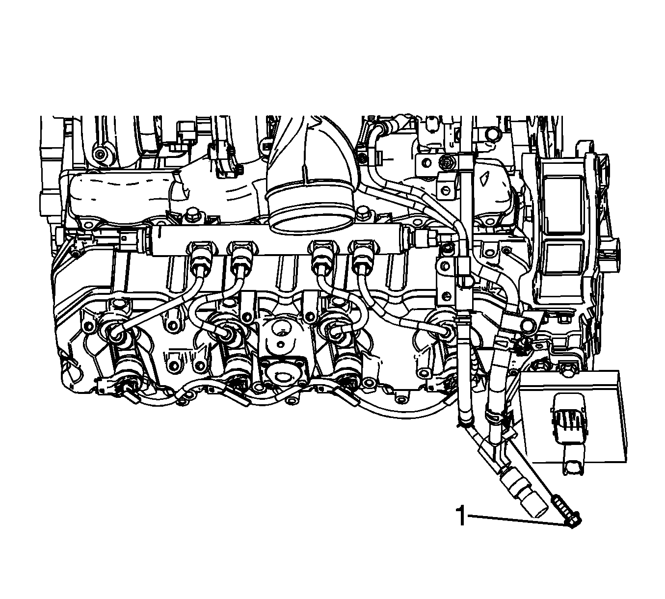
- Remove the fuel injection fuel feed manifold side bolt (1).
- Reposition the fuel injection fuel feed manifold up out of the way.
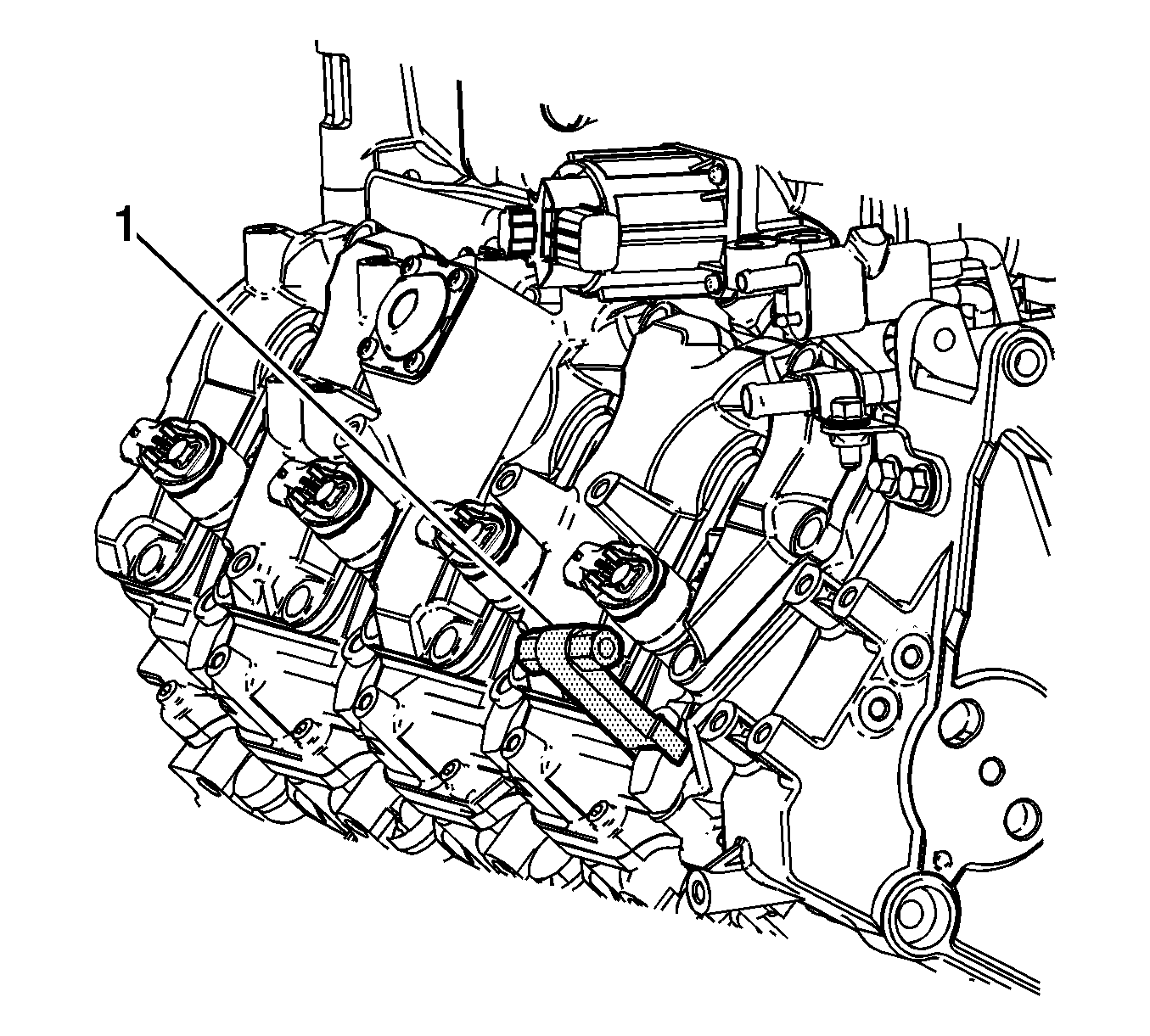
- Remove the fuel return hose clips (1).
- Remove the fuel return hose from the injectors.
- Disconnect the engine wiring harness electrical connectors from the fuel injector(s).
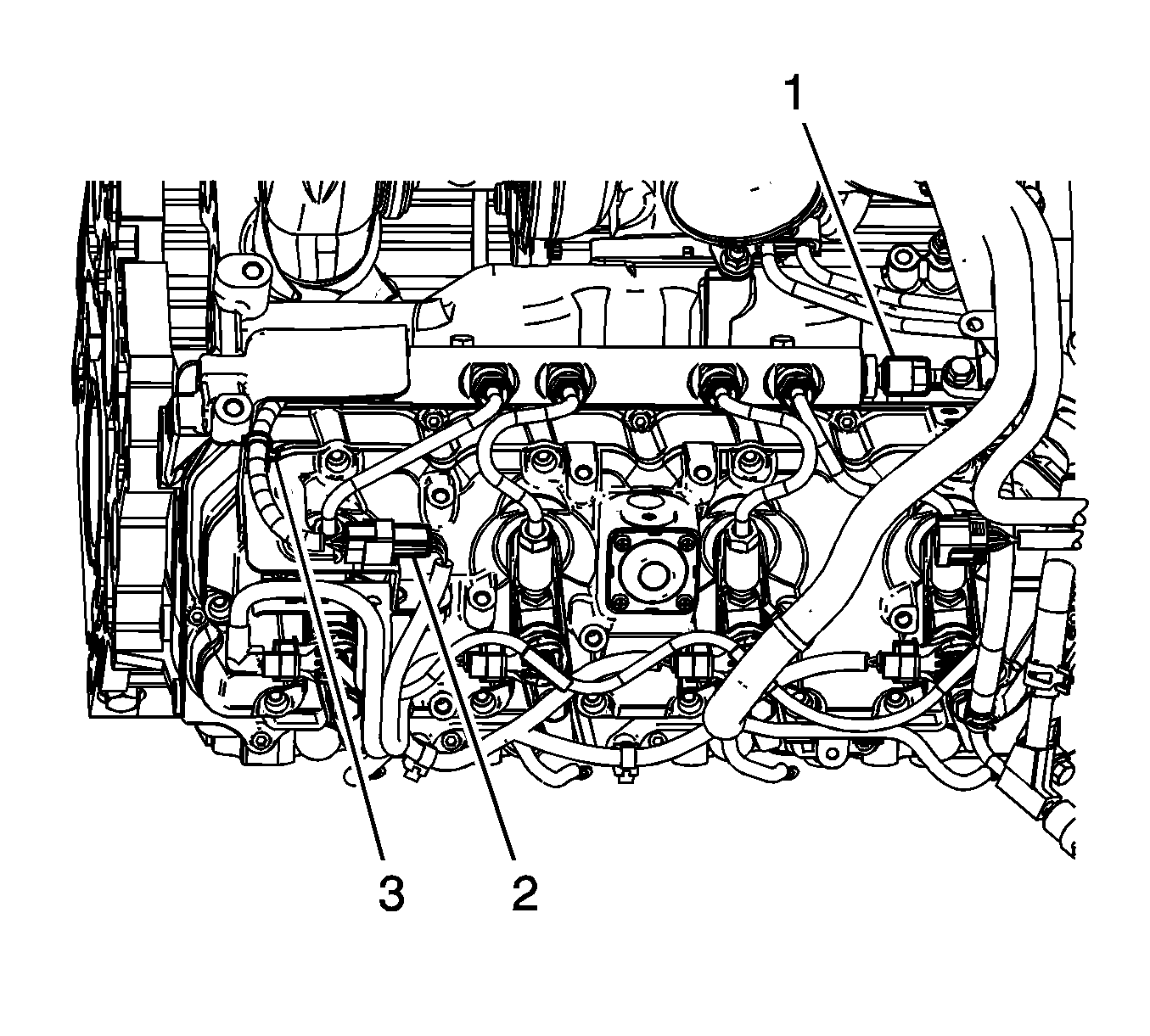
- Disconnect the engine wiring harness electrical connector (2) from the fuel rail fuel pressure sensor wiring harness electrical connector.
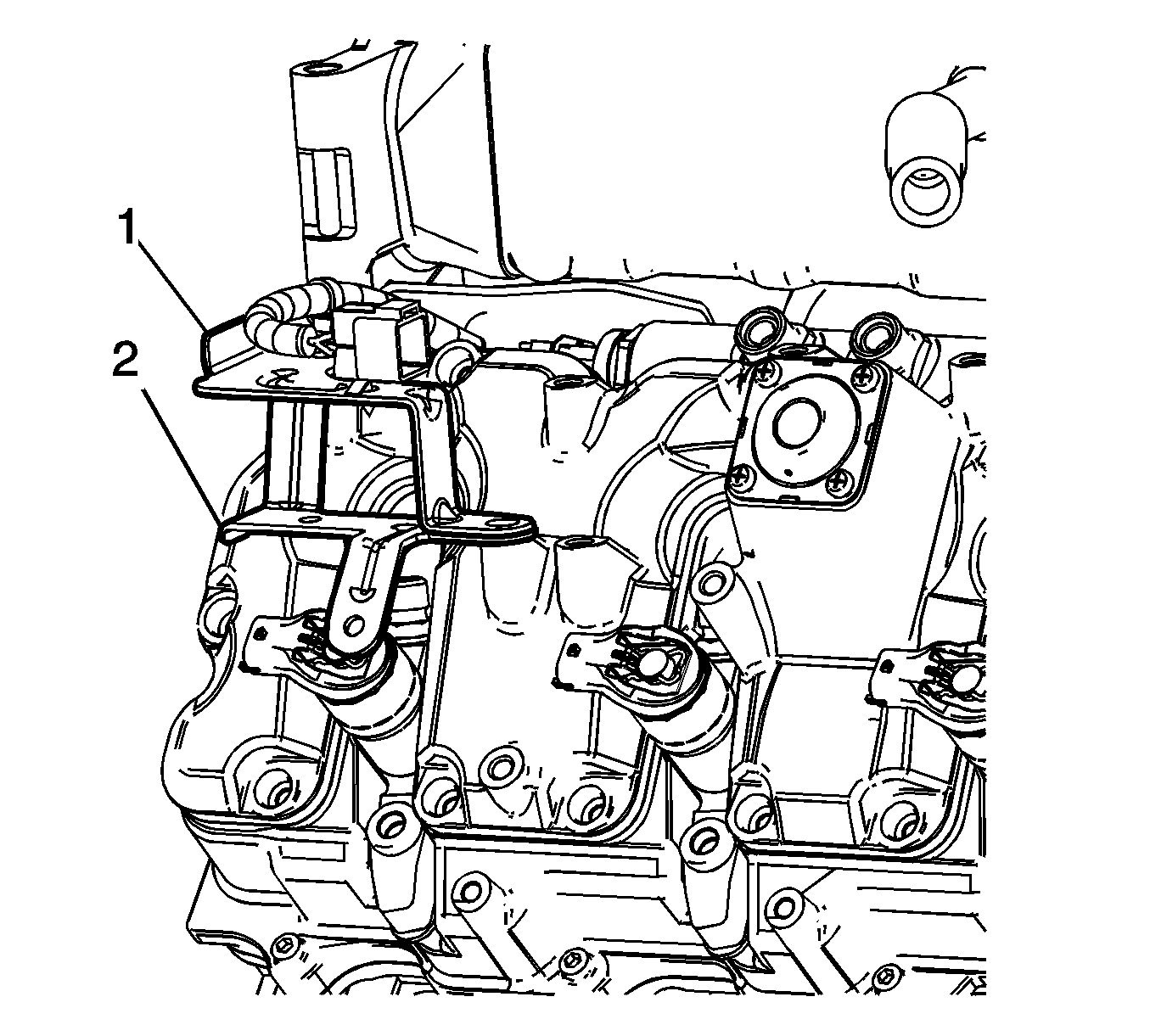
- Unbolt and reposition the rear wiring harness brackets (1 and 2).
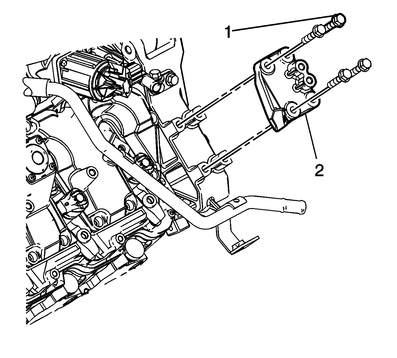
- Remove the fuel pipe bracket bolts (1) and bracket (2).
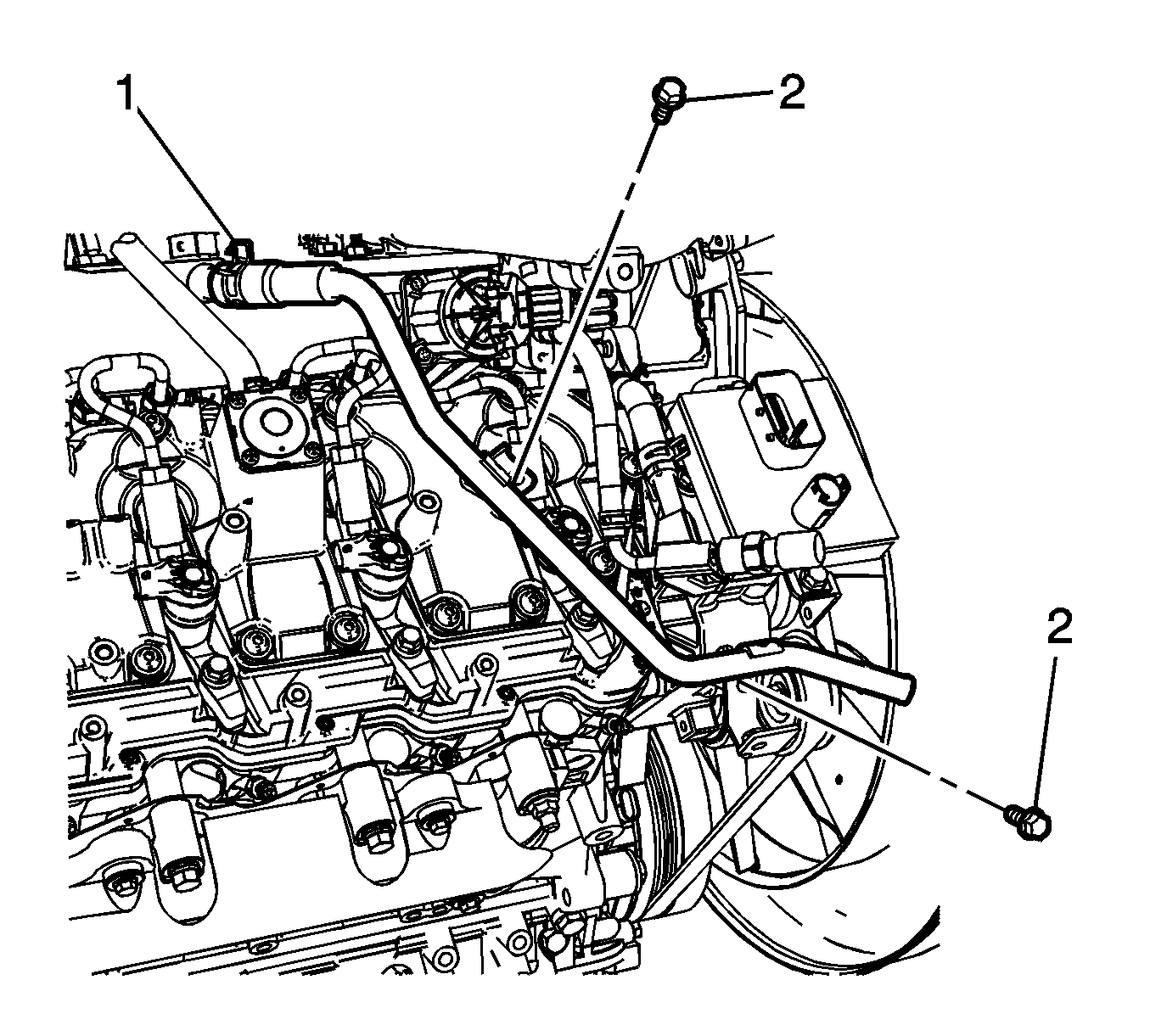
- Reposition the heater pipe to exhaust gas recirculation (EGR) valve cooler hose clamp (1).
- Remove the heater pipe bolts (2).
- Disconnect the heater pipe from the EGR cooler valve hose, and reposition the heater pipe out of the way.
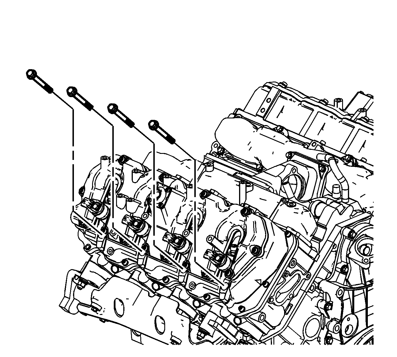
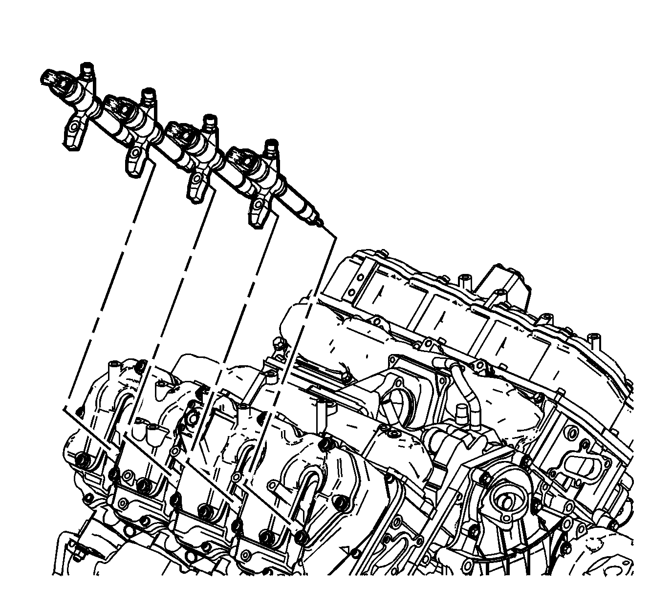
- Remove the fuel injector bracket bolts.
- Install the J-46594 (1) into the bolt hole in the fuel injector bracket.
- Install a flare nut wrench onto the J-46594 and pull back away from the fuel injector, until the injector releases from its seat.
- Remove the J-46594 .
- Remove the fuel injectors with brackets.
- If necessary, remove the fuel injector bracket pins.
- Remove and discard the copper washer from the fuel injector bore.
- Remove and discard the O-ring from the fuel injector.



Fuel Injector Cleaning and Inspection
Important: If reusing the old injectors perform the following:
- Use a soft bristle non-metallic brush and Top Engine Cleaner, GM P/N 1052626 or equivalent, to remove any deposits from the nozzle tip (1) and the copper washer sealing area (2) before re-installation.
- Inspect the fuel injector nozzle tip (1) for any signs of discoloration (dark yellow, tan or blue) due to excessive heat.
- Replace the injector if any damage is found.
- Clean the fuel injector high pressure line.
- Inspect the fuel injector line for excessive corrosion or damage to the sealing surfaces (1, 2). Replace the line if any damage is found.


Injector Bore Cleaning
Important: The procedure below will aid in the cleaning of carbon deposits from the injector sleeve during an injector replacement
- Install the EN-47909-2 Radial Brush (brass), to the EN-47909-1 Handle Assembly.
- Insert the brush into the injector bore and rotate the handle in order to break loose any carbon deposits from the injector bore walls and the combustion deck hole.
- Using compressed air, evacuate any debris from the injector bore.
- Remove the radial brush from the handle assembly.
- Install the EN-47909-3 Axial Brush (nylon), to the EN-47909-1.
- Insert the axial brush into the injector bore and rotate the handle while also applying a slight downward pressure, in order to force the brush ends into the bottom corners of the injector bore.
- Using compressed air, evacuate any debris from the injector bore.
- Lightly dampen EN-47909-20 Cotton Swab with Top Engine Cleaner, GM P/N 1052626 (Canadian P/N 993026) or equivalent, and wipe away any deposits from the injector bore.
- Inspect the injector bore for any deposits and repeat brushing if necessary.
- If necessary, crank the engine in order to expel any solvent before starting the engine.

Caution: Wear safety glasses in order to avoid eye damage.
Caution: Wear safety glasses in order to avoid eye damage.
Notice: Do not allow excessive amounts of solvent to go into the cylinder during cleaning. Failure to do so may cause engine damage upon startup.
Caution: Keep hands and face clear of glow plug holes while cranking. Hot liquid or gases may be expelled during cranking.
Caution: Wear safety glasses in order to avoid eye damage.
| 10.1. | Remove the glow plugs. Refer to Glow Plug Replacement - Bank 1 and/or Glow Plug Replacement - Bank 2 . |
| 10.2. | Disable the fuel system. |
| 10.3. | Disconnect the engine wiring harness electrical connector from the crankshaft position (CKP) sensor. |
| 10.4. | Crank the engine in order to expel any excessive solvent. |
| 10.5. | Using the cotton swabs supplied with the kit, wipe the injector bore clean of any solvent and/or debris. |
| 10.6. | Connect the engine wiring harness electrical connector to the CKP sensor. |
| 10.7. | Enable the fuel system. |
| 10.8. | Reinstall the glow plugs. Refer to Glow Plug Replacement - Bank 1 and/or Glow Plug Replacement - Bank 2 . |
Installation Procedure
- Install a NEW copper washer(s) to the fuel injector bore(s).
- Install a NEW O-ring onto the fuel injector(s).
- If necessary, install the fuel injector bracket pins.
- Install the fuel injectors with brackets.
- Install the fuel injector bracket bolts.
- Position the heater pipe and connect the heater pipe to the EGR cooler valve hose.
- Install the heater pipe bolts (2).
- Position the heater pipe to EGR valve cooler hose clamp (1).
- Position the fuel pipe bracket (2) and install the bolts (1).
- Position the rear wiring harness brackets (1 and 2) and install the bolts.
- Connect the engine wiring harness electrical connector (2) to the fuel rail fuel pressure sensor wiring harness electrical connector.
- Connect the engine wiring harness electrical connectors to the fuel injector(s).
- Install the fuel return hose to the injectors.
- Install the fuel return hose clips (1).
- Position the fuel injection fuel feed manifold to the fuel pipe bracket.
- Install the fuel injection fuel feed manifold side bolt (1).
- Install the right side fuel injection fuel feed pipes. Refer to Fuel Injection Fuel Feed Pipe Replacement - Right Side .
- Install the glow plug control module. Refer to Glow Plug Control Module Replacement .
- Install the air cleaner . Refer to Air Cleaner Assembly Replacement .
- Install the engine cover. Refer to Engine Cover Replacement .
- Fill the engine cooling system. Refer to Cooling System Draining and Filling .
- If the fuel injectors were replaced, Refer to Fuel Injector Flow Rate Programming
- Prime the fuel system. Refer to Fuel System Priming .
- Start the engine. If the engine stalls, repeat the above step.
- Once the engine starts, inspect for fuel leaks.

Notice: Refer to Fastener Notice in the Preface section.

Tighten
Tighten the bolts to 30 N·m (22 lb ft).

Tighten
Tighten the bolts to 24 N·m (18 lb ft).

Tighten
Tighten the bolts to 25 N·m (18 lb ft).

Tighten
Tighten the bolts to 25 N·m (18 lb ft).


Tighten
Tighten the bolt to 25 N·m (18 lb ft).
