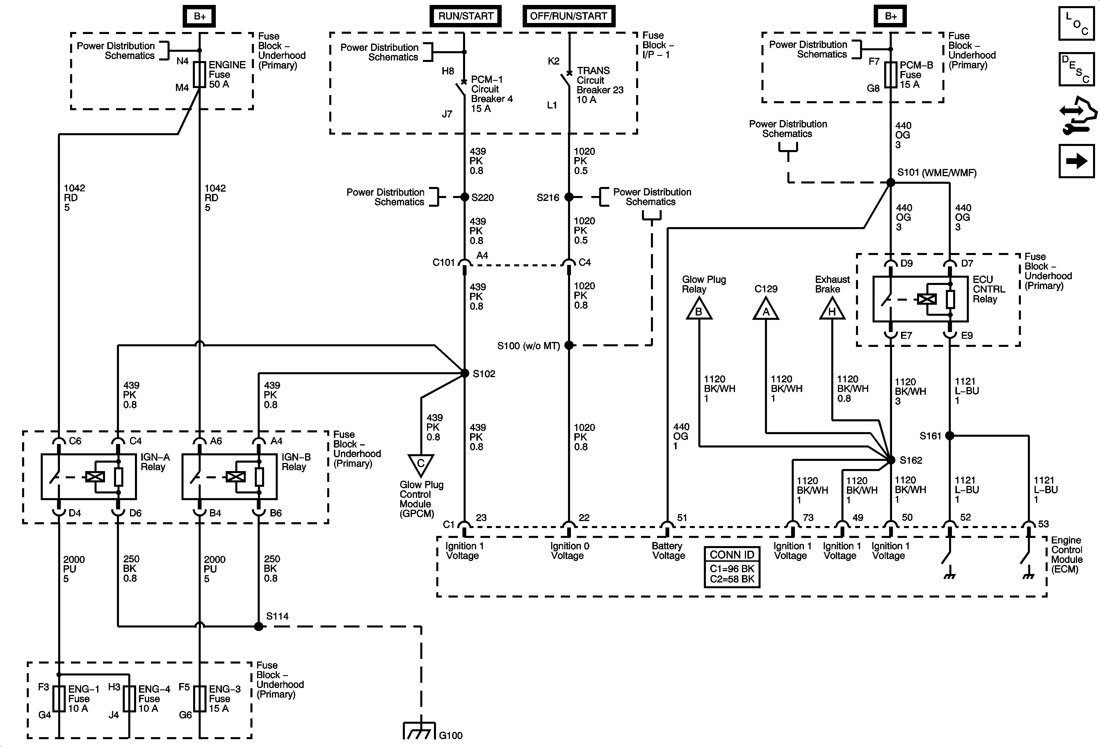
| Figure 1: |
Module Power
|
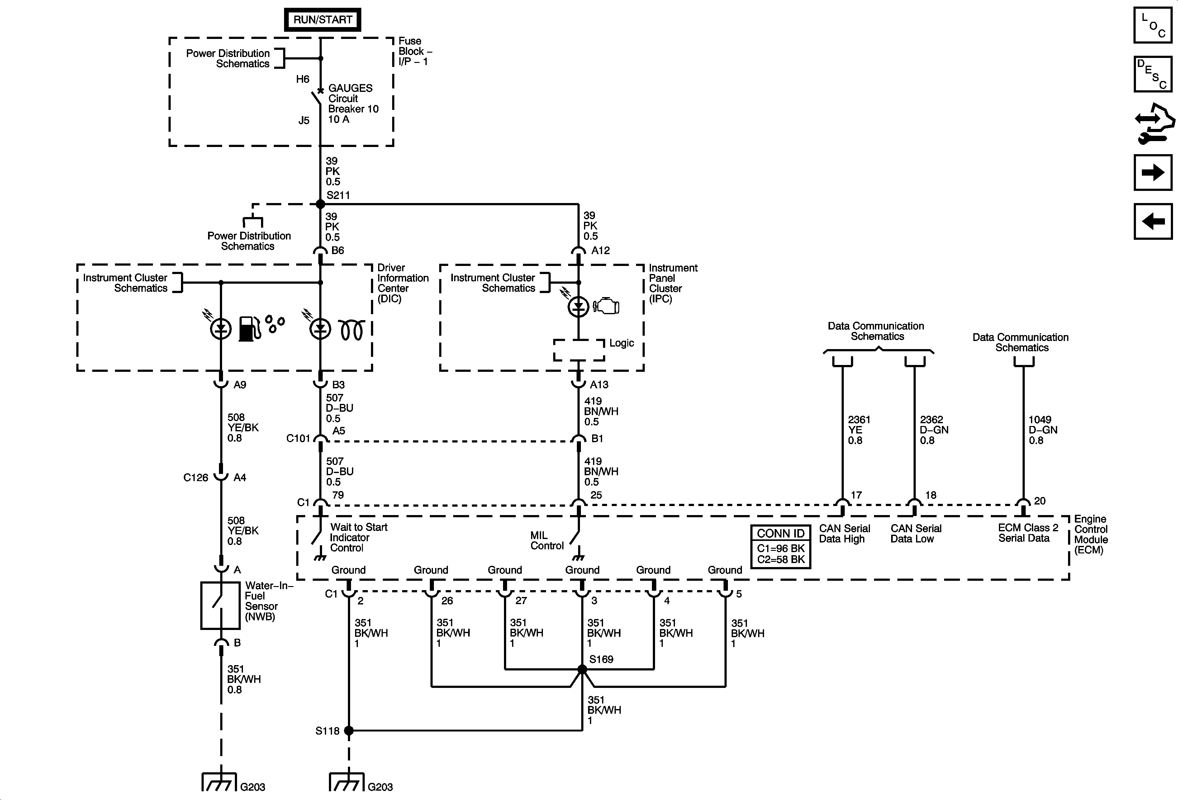
| Figure 2: |
Module Ground, Serial Data, and MIL, Wait to Start, Water in Fuel Indicators
|
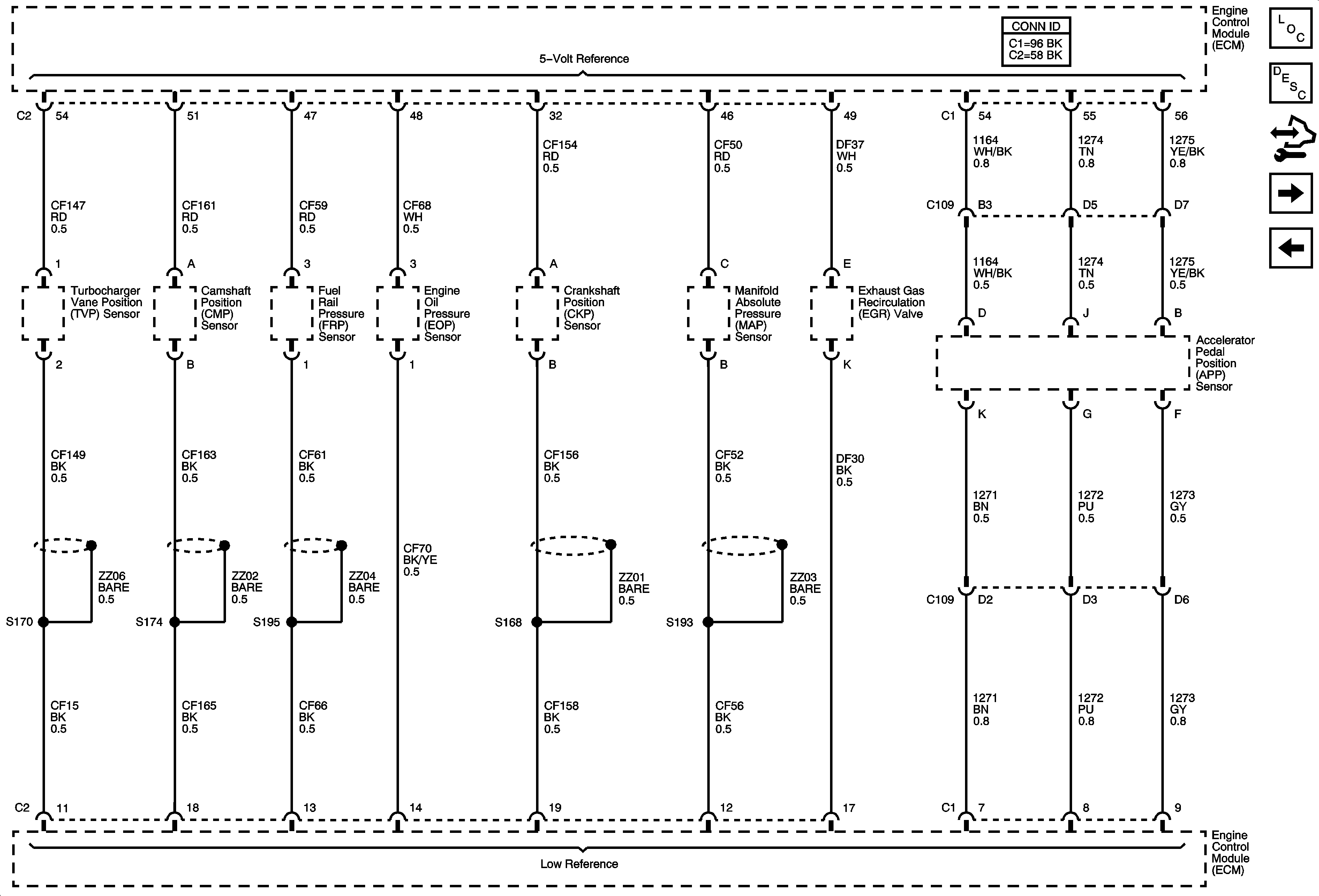
| Figure 3: |
Engine Data Sensors - 5-Volt and Low Reference
|
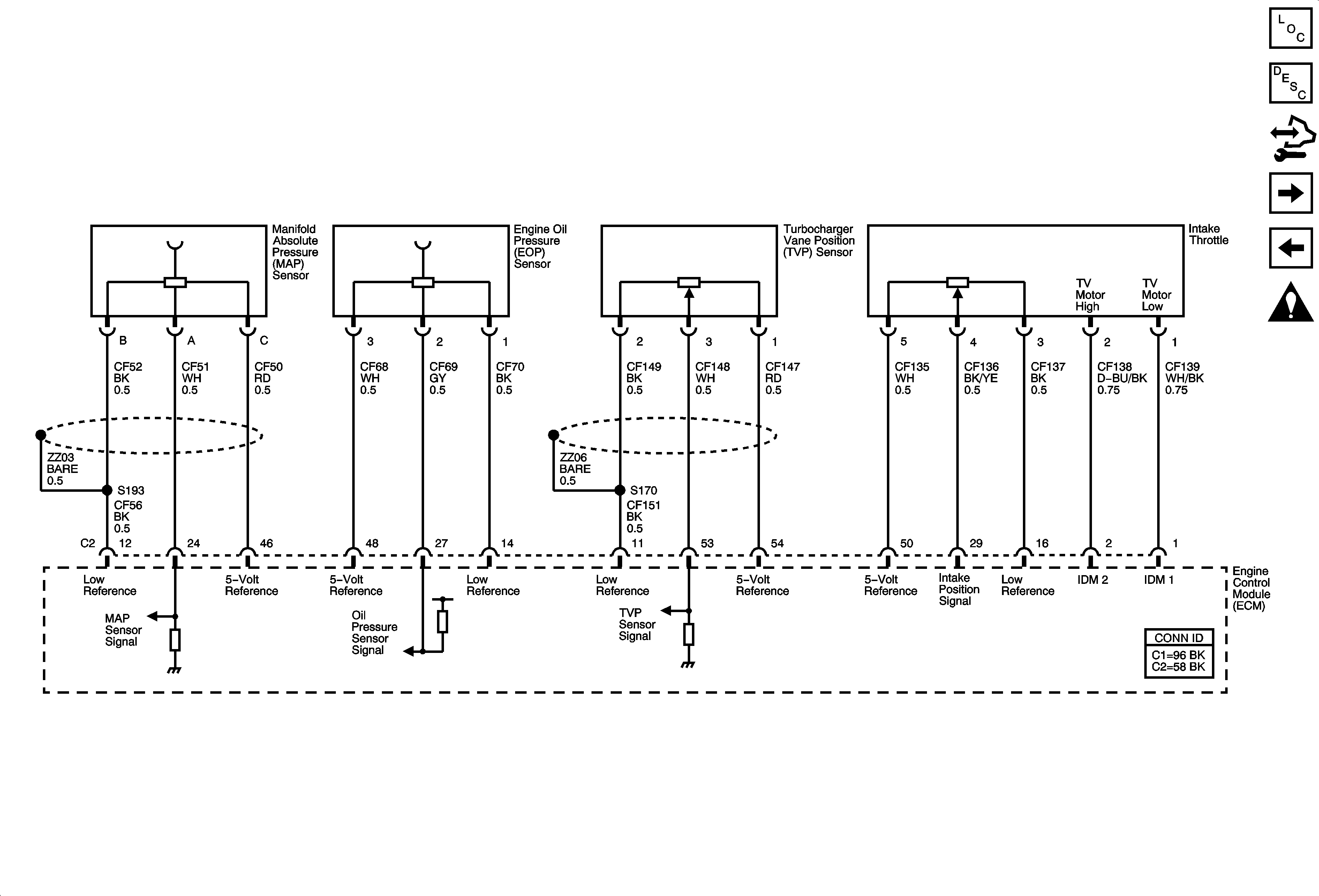
| Figure 4: |
Engine Data Sensors - Manifold, and Engine Oil Pressure, Turbocharger Vane Position, and Intake Throttle
|
| Figure 5: |
Engine Data Sensors - Mass Air Flow, Temperature, and Turbocharger Vane Position Control

|
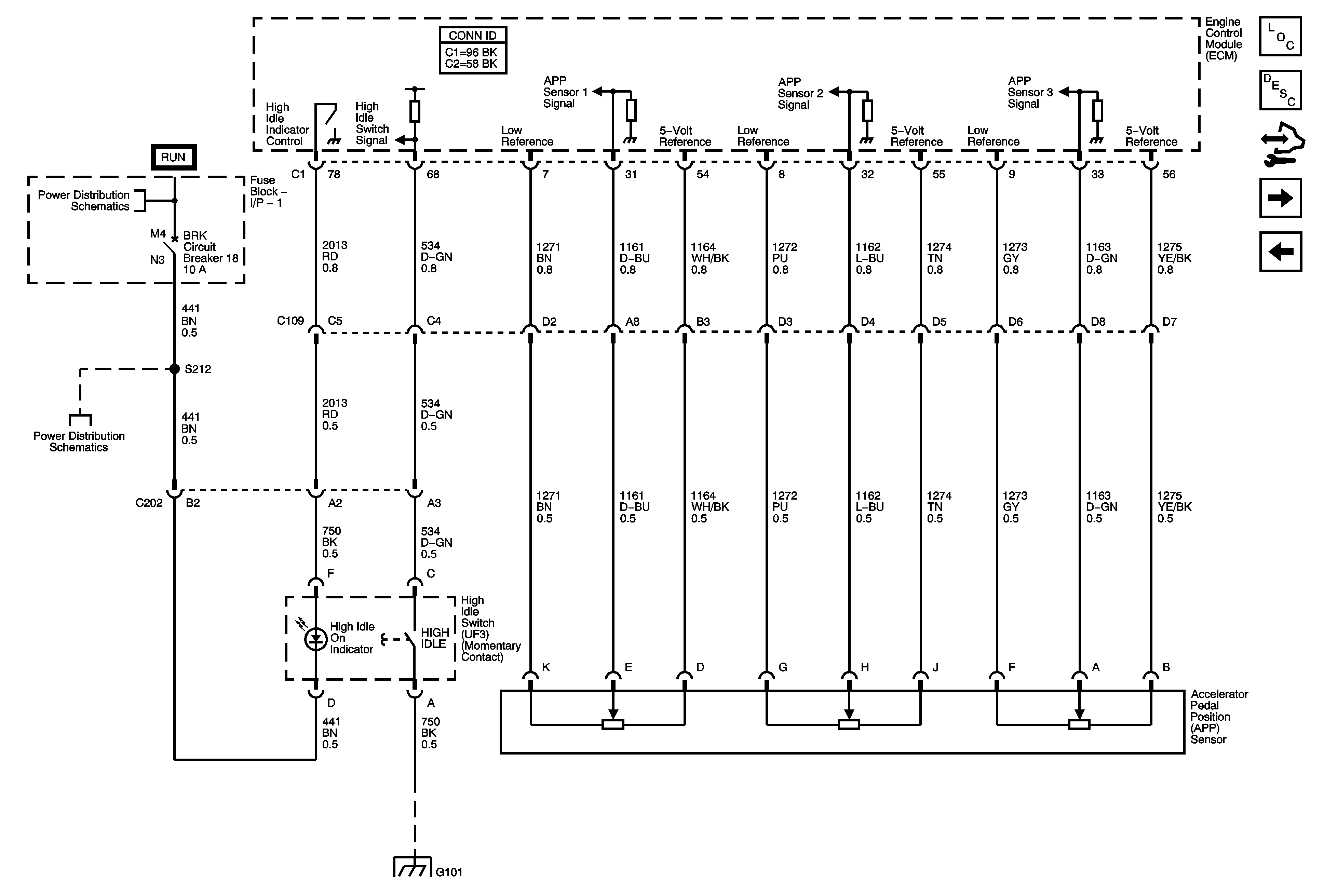
| Figure 6: |
Engine Data Sensors - APP Sensor and High Idle Switch - UF3
|
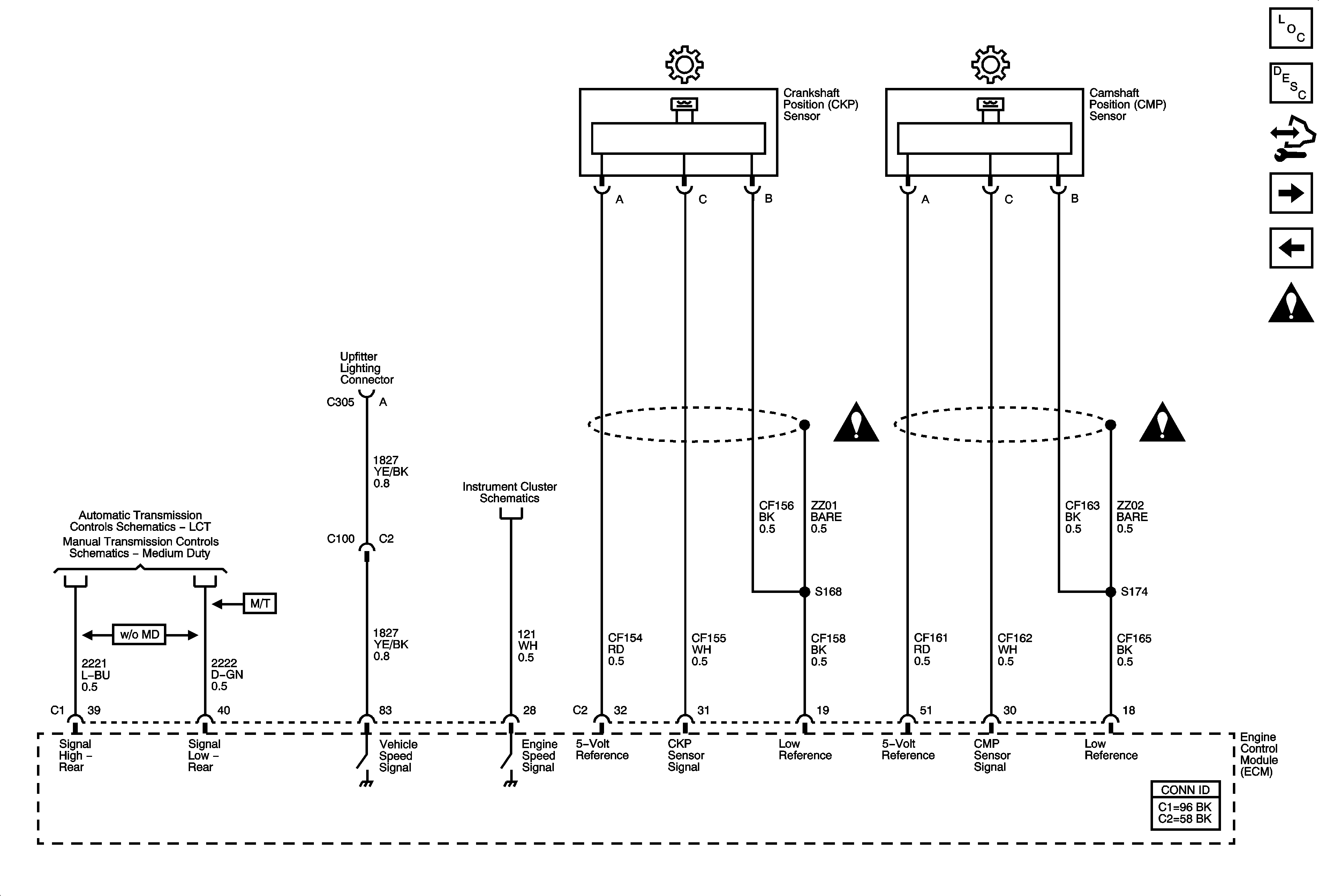
| Figure 7: |
Engine Data Sensors - VSS and Injector Timing Controls
|
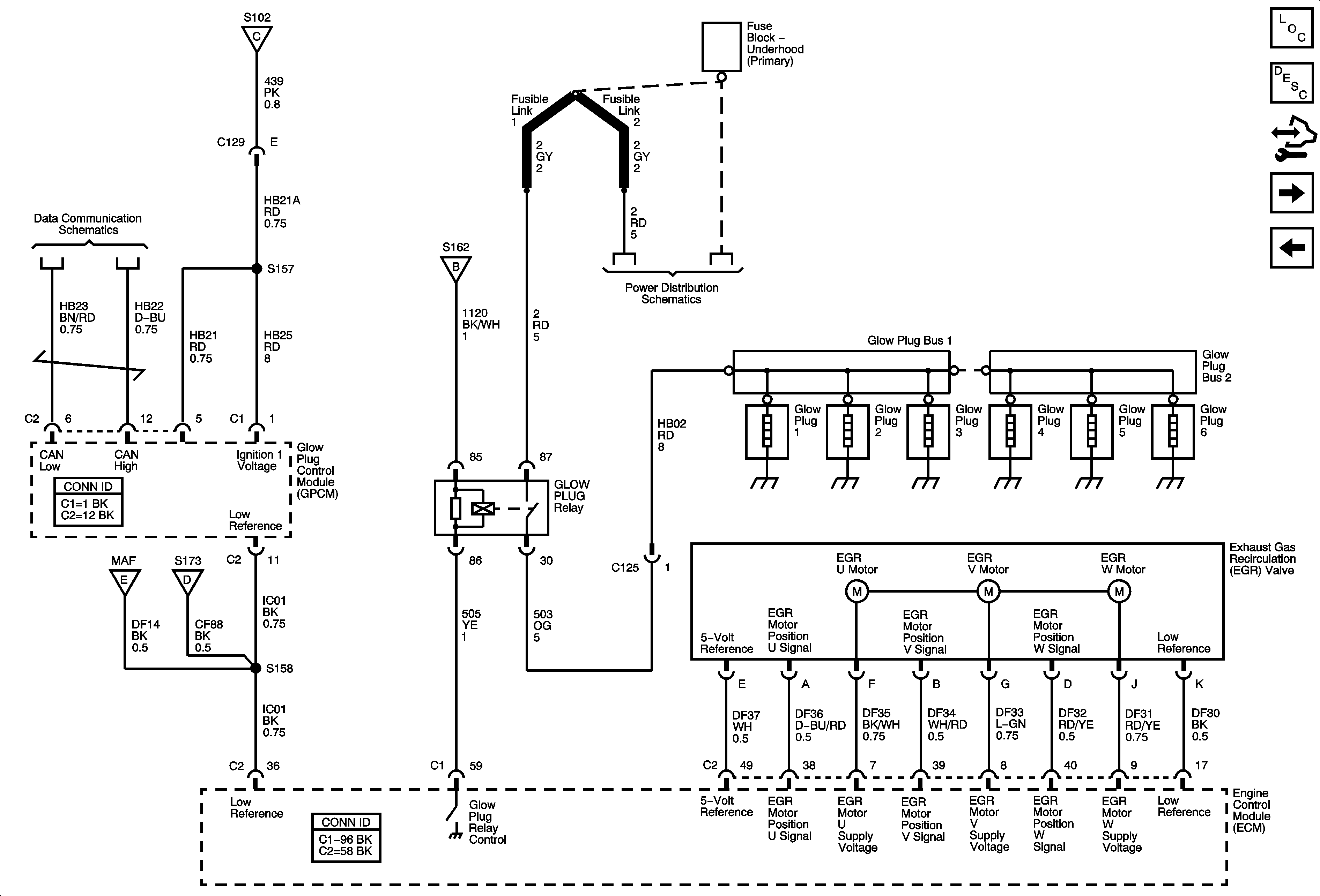
| Figure 8: |
Engine Data Sensors - EGR Valve and Glow Plug Controls
|
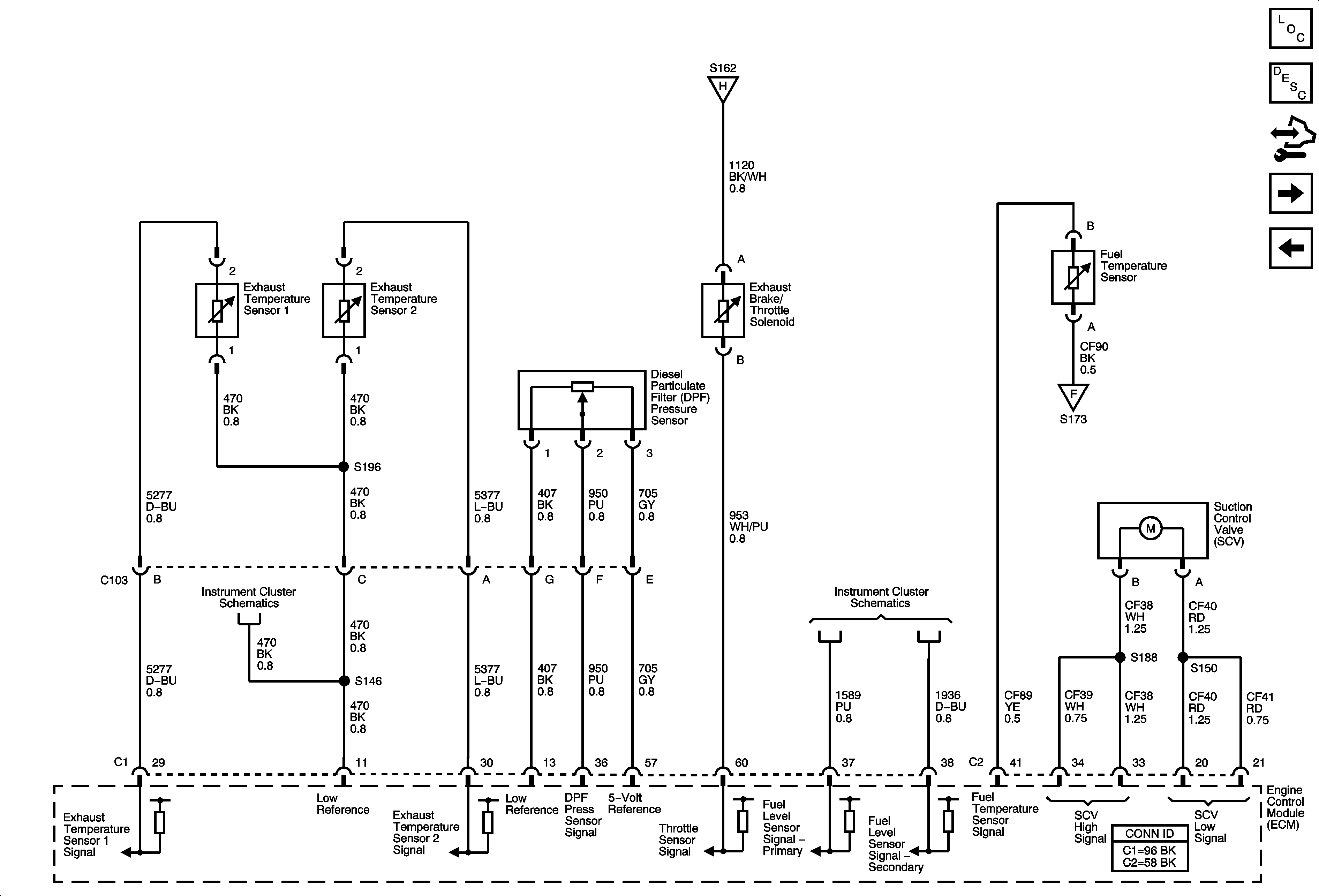
| Figure 9: |
Fuel Controls - Fuel Sensors, Suction Control Valve (SCV), Exhaust Temperature, DPF Pressure Sensor, and Exhaust Brake Solenoid
|
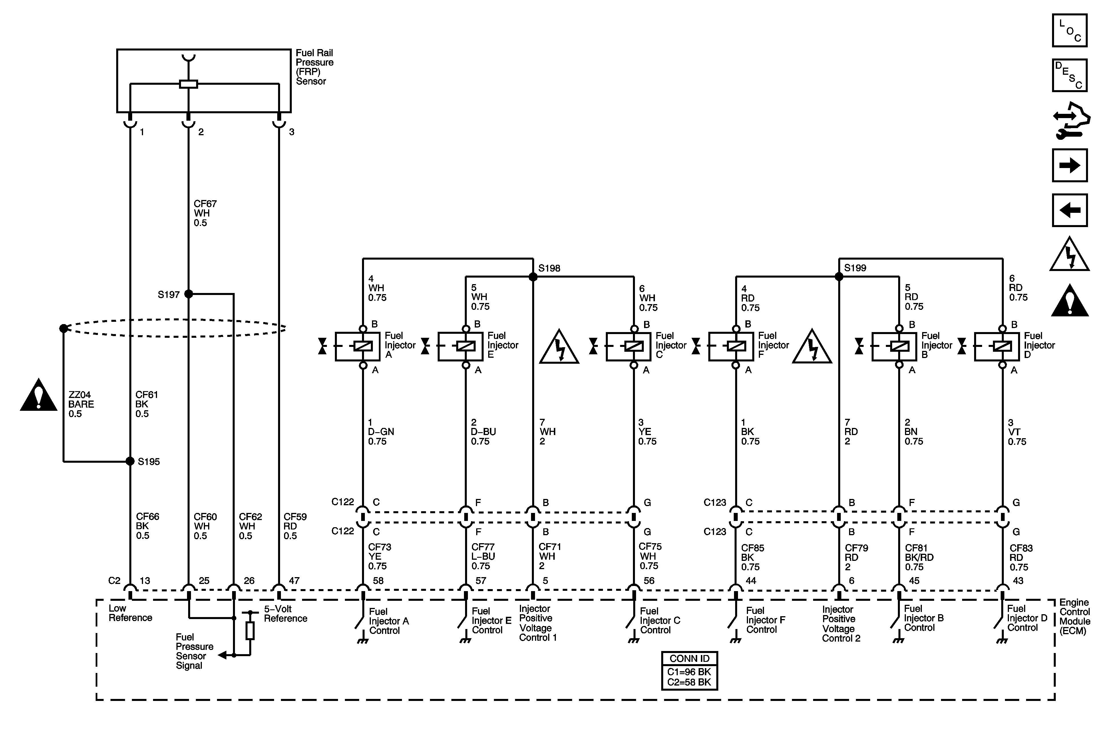
| Figure 10: |
Fuel Controls - Fuel Injectors, Fuel Rail Pressure Sensor
|
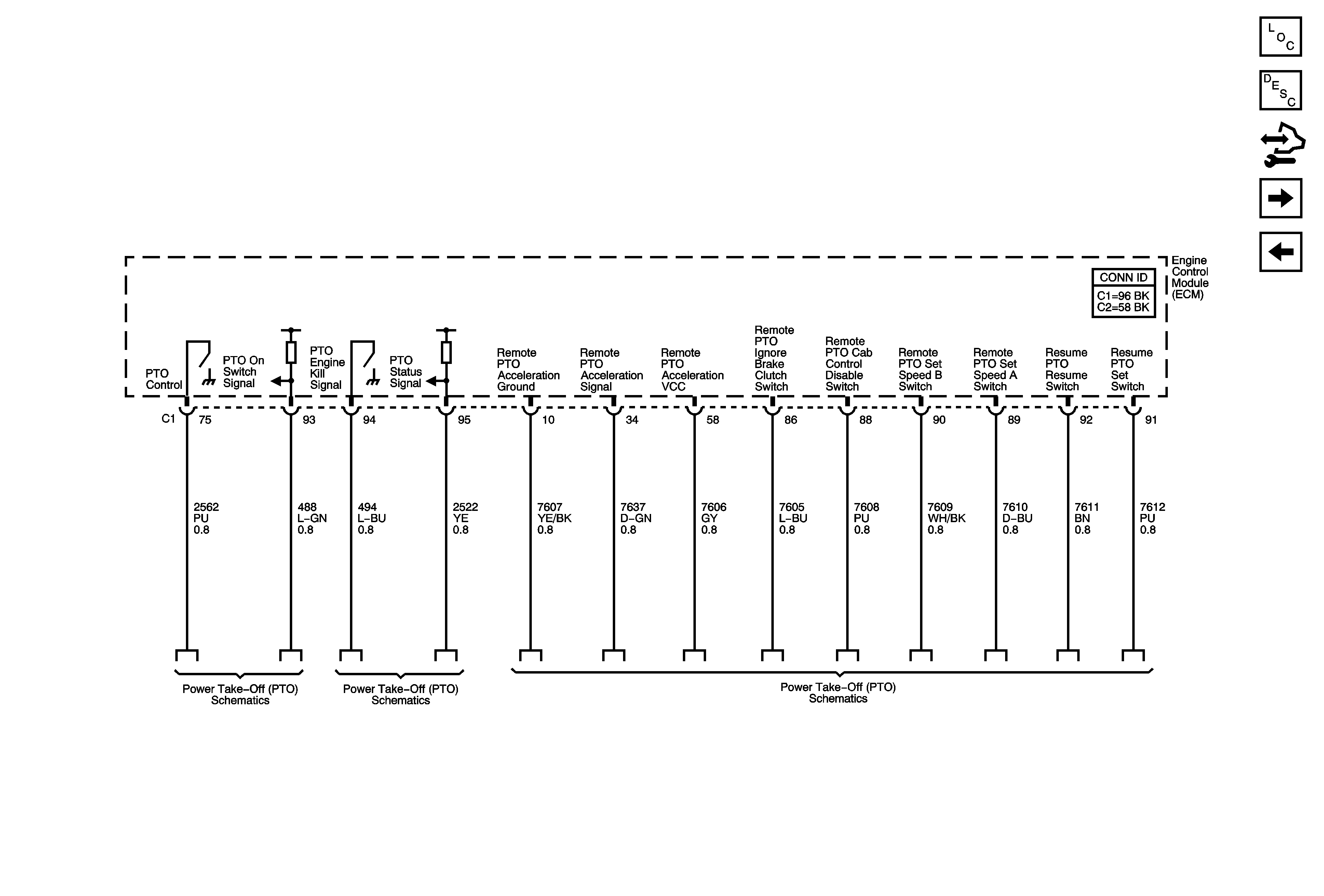
| Figure 11: |
Power Take Off (PTO) System References
|
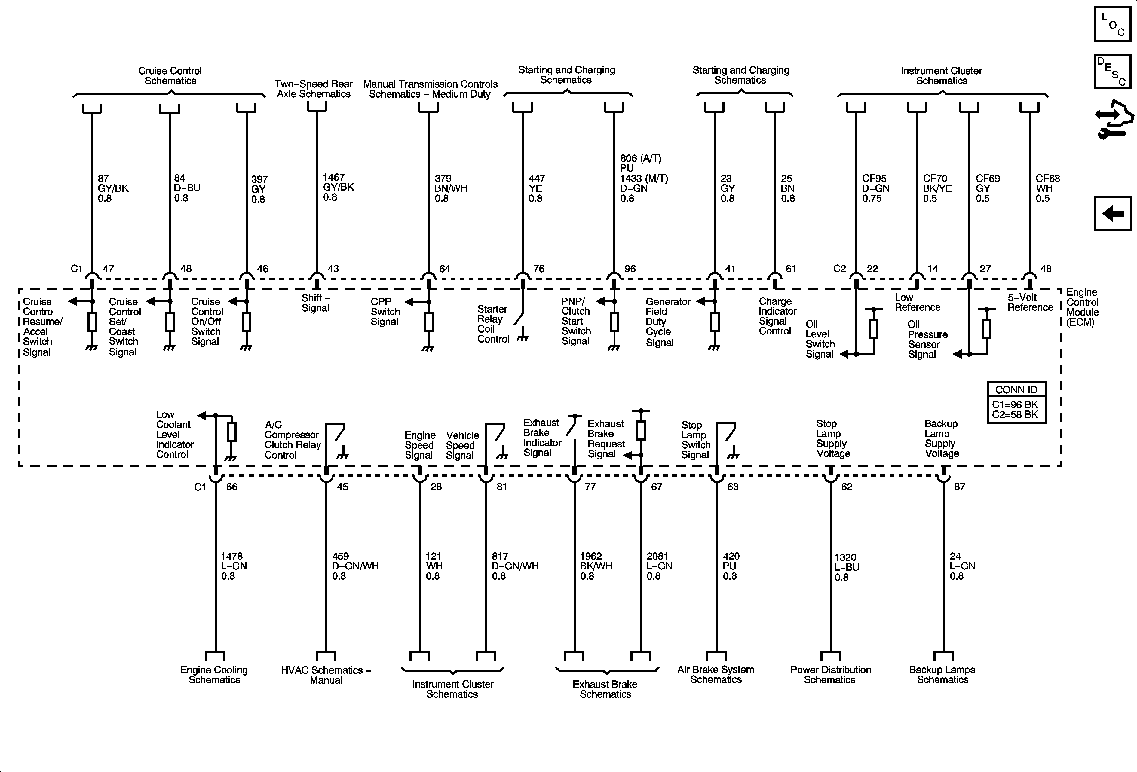
| Figure 12: |
Controlled/Monitored Subsystem References
|
