For 1990-2009 cars only
Removal Procedure
- Remove the engine control module (ECM).
- Remove the transmission control module (TCM), if equipped. Refer to Transmission Control Module Replacement.
- Remove the air cleaner. Refer to Air Cleaner Assembly Replacement.
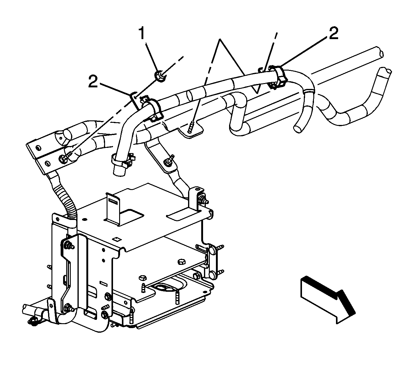
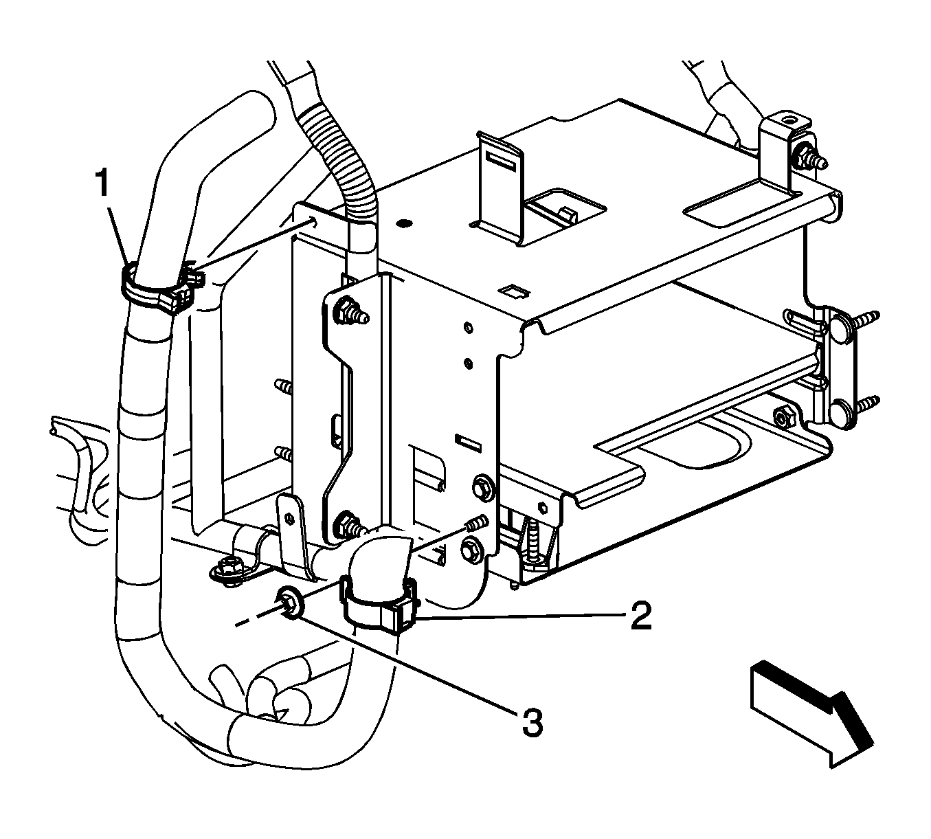
- Remove the 2 engine wiring harness clip nuts (1).
- Remove the 2 engine wiring harness clips (2) from the air cleaner support.
- Remove the air cleaner support stud (2).
- Remove the 4 air cleaner support nuts (2).
- Remove the air cleaner support (1).
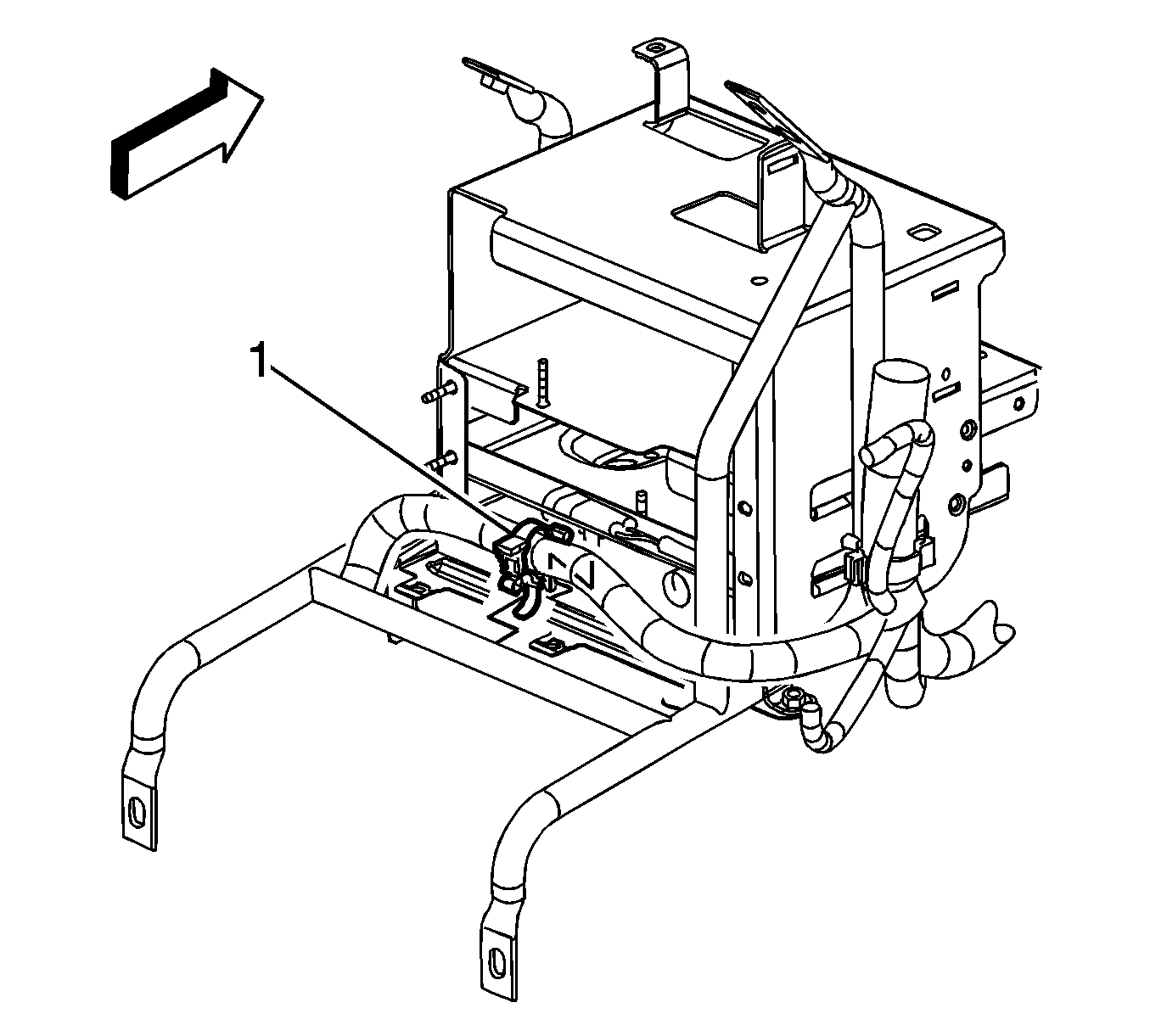
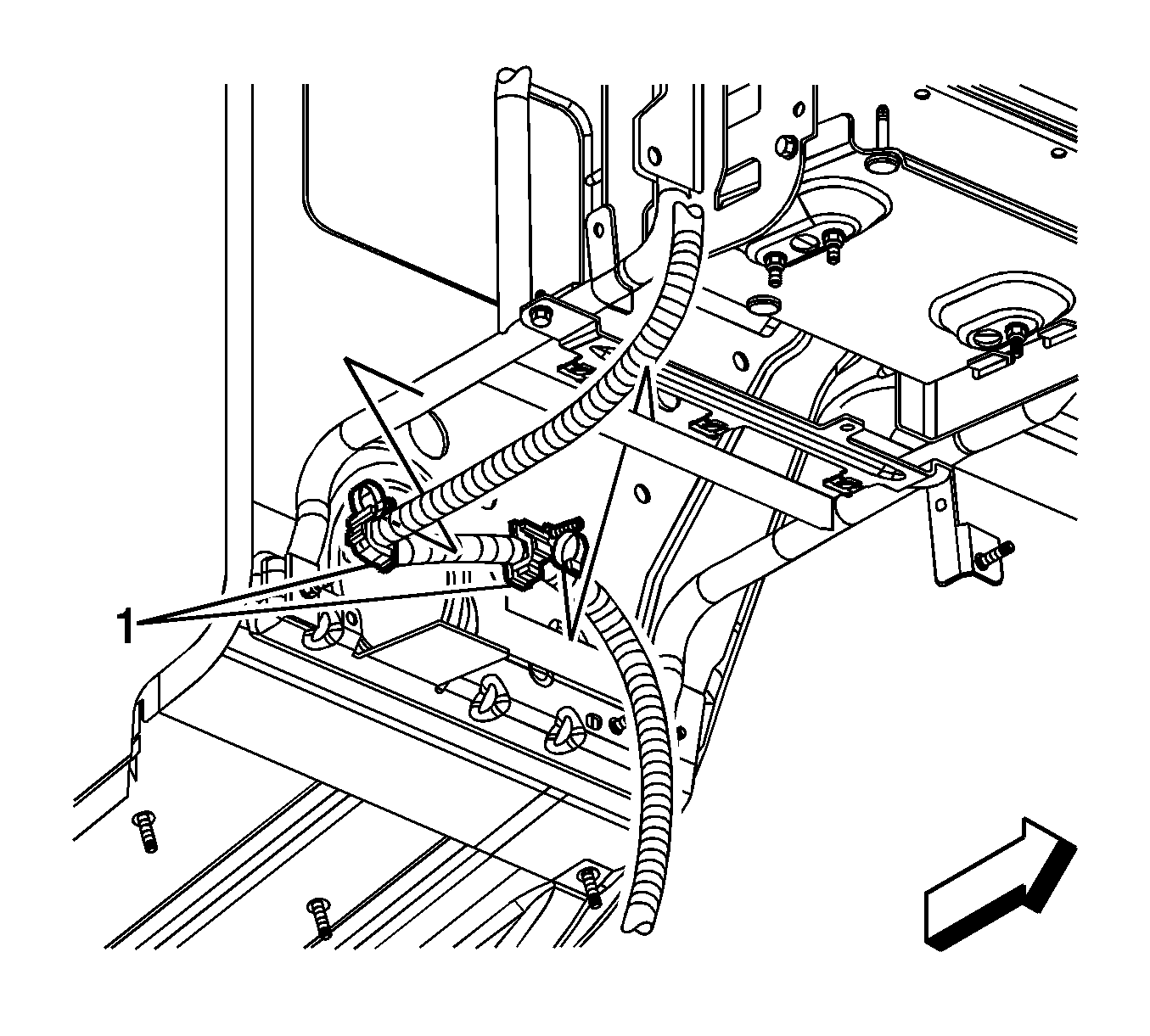
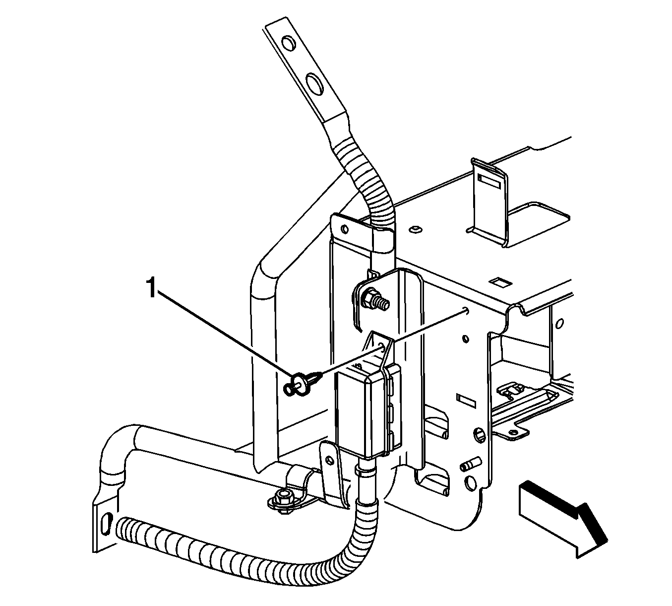
- Remove the engine wiring harness clip (1) from the multi-use module bracket.
- Remove the engine wiring harness electrical connector clip (1) from the multi-use module bracket.
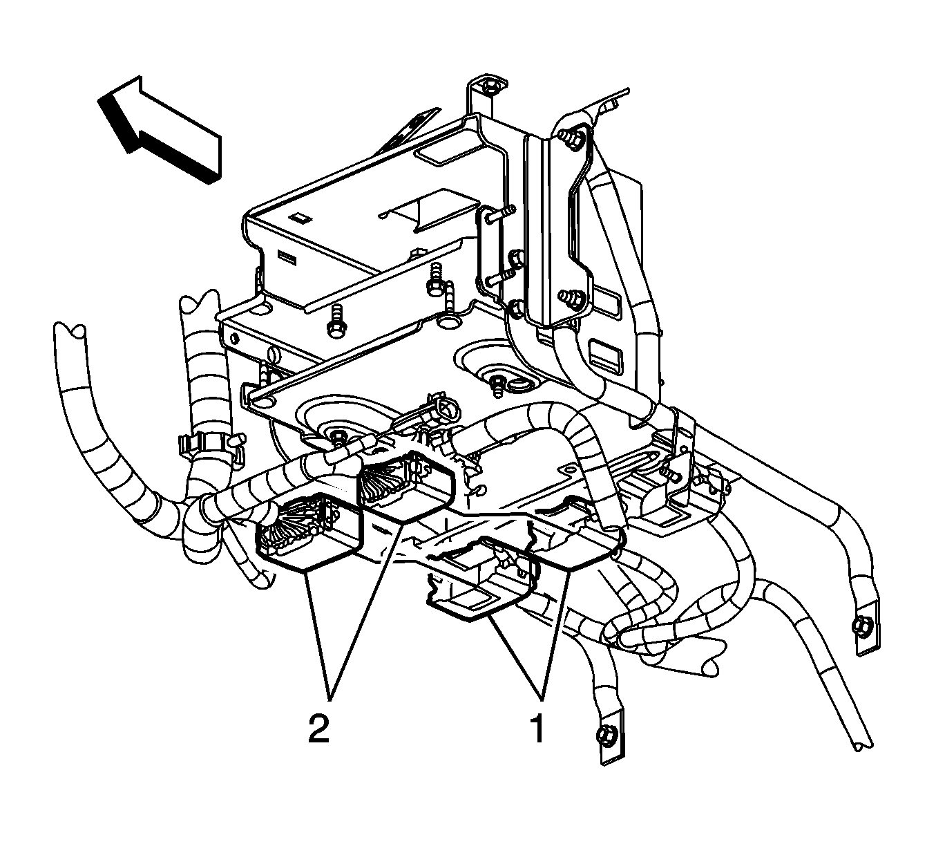
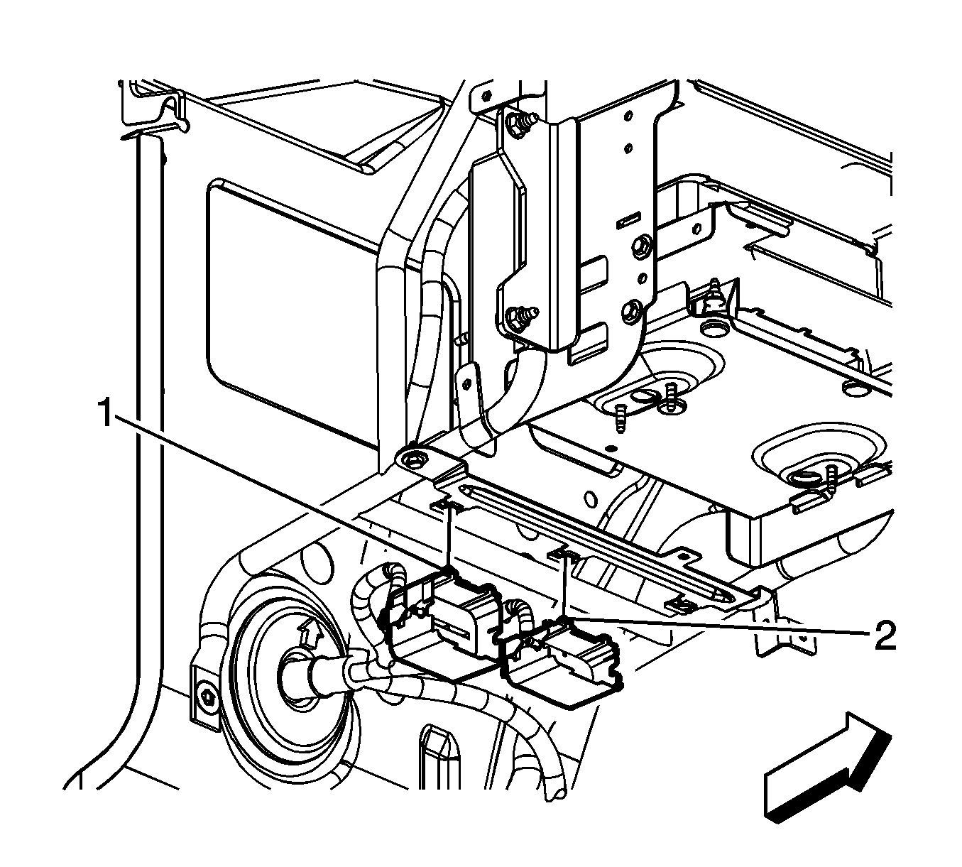
- Disconnect the engine wiring harness electrical connectors (2) from the instrument panel (I/P) wiring harness electrical connectors (1).
- From the rear of the I/P wiring harness electrical connectors, disengage the multi-use module bracket retainers from the electrical connector clips (1, 2).
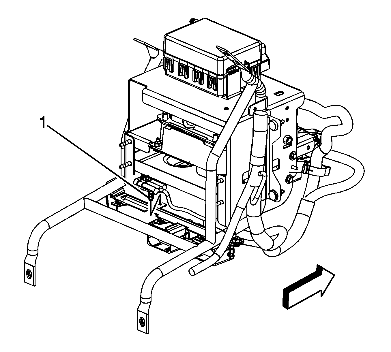
- Remove the battery cable clips (1) from the multi-use module bracket.
- Remove the engine wiring harness clip (1) from the multi-use module bracket clip.
- Remove the engine wiring harness clip nut (3) from the multi-use module bracket stud.
- Remove the engine wiring harness clip (2) from the multi-use module bracket stud.
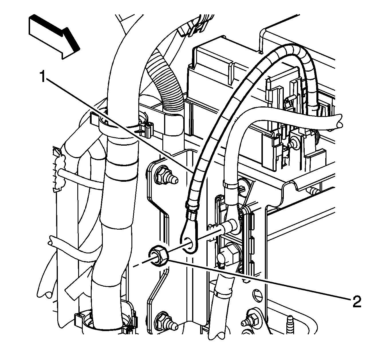
- Open the battery cable junction block cover, and remove the I/P wiring harness lead nut (2) and lead (1) from the junction block.
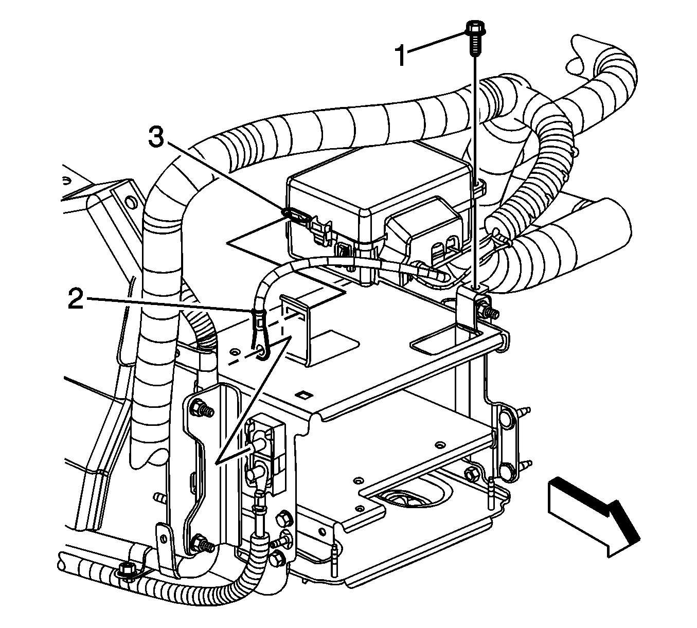
- Remove the engine wiring harness underhood electrical center bolt (1).
- Remove the engine wiring harness lead (2) from the junction block.
- Tilt the underhood electrical center toward the passenger side in order to remove the electrical center tab (3) from the multi-use module bracket.
- Remove the I/P wiring harness maxi-fuse connector bolt (1).
- Remove the I/P wiring harness maxi-fuse connector from the multi-use module bracket.
- Remove the battery cable junction block retainer (1) from the multi-use module bracket.
- Tilt the top of the junction block outward and lift the bottom of the junction block up in order to remove the junction block clip from the multi-use module bracket.
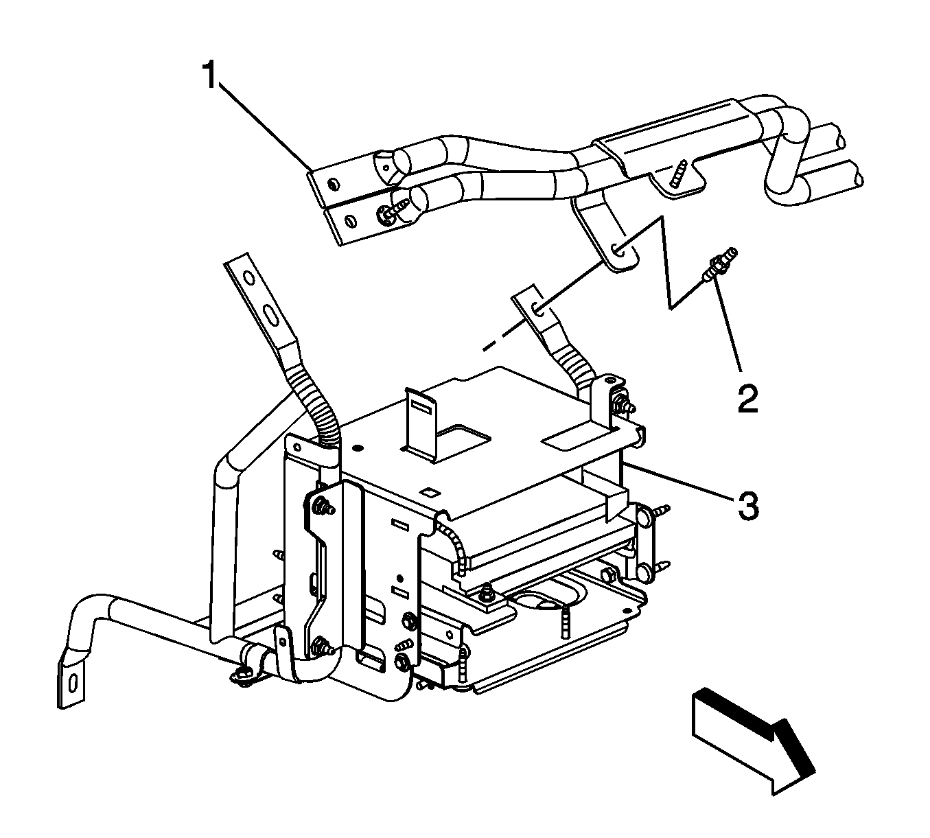
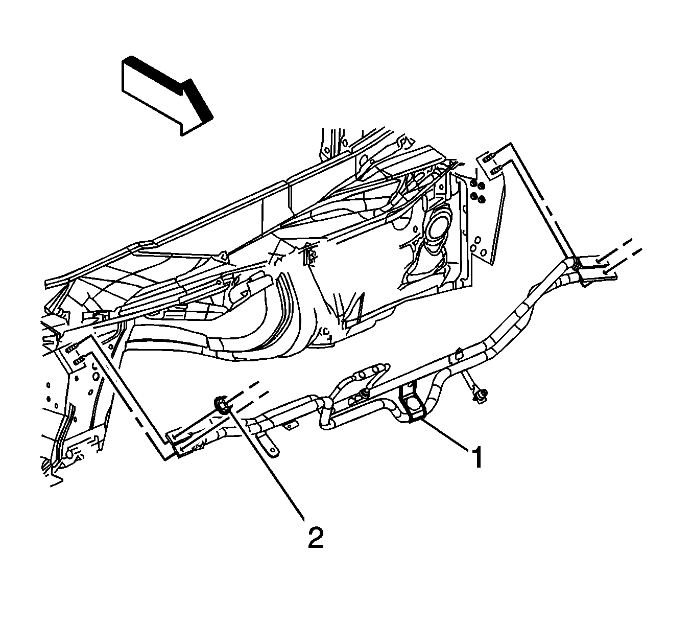
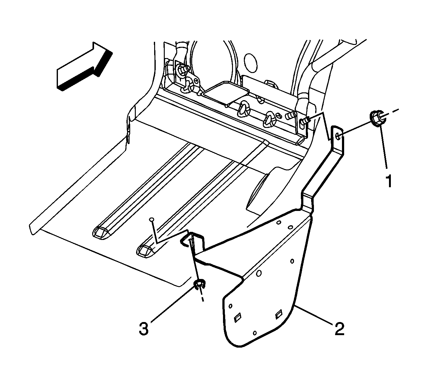
- Remove the chassis harness bracket nuts (1, 3).
- Remove the chassis harness bracket (2) from the dash panel stud and reposition out of the way.
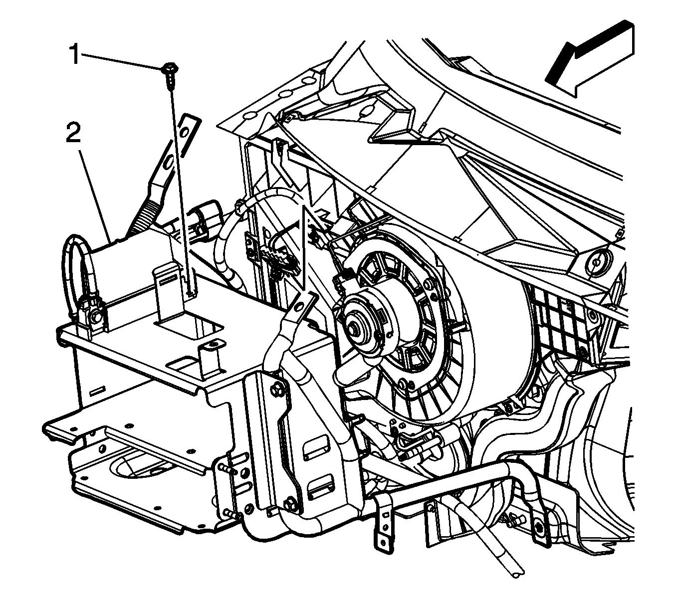
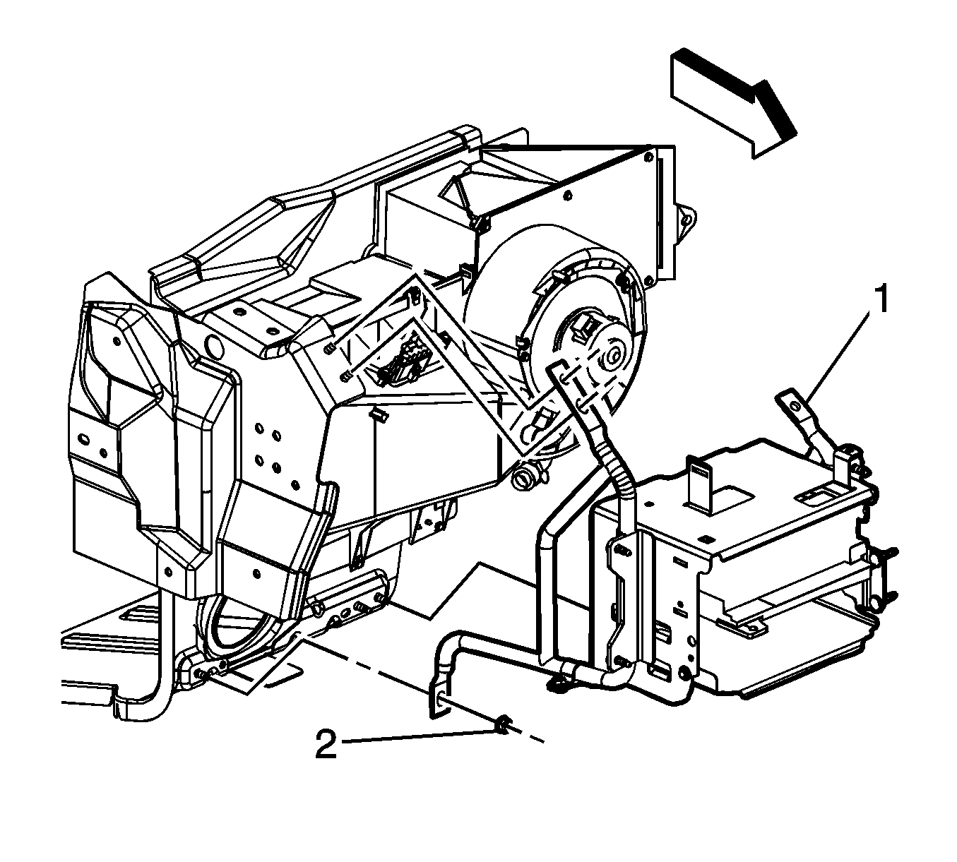
- Remove the multi-use module bracket nut (2).
- Remove the multi-use module bracket assembly (1) from the vehicle.
Installation Procedure
- Install the multi-use module bracket assembly (1) to the vehicle.
- Install the multi-use module bracket nut (2).
- Position the chassis harness bracket (2) and install the bracket to the dash panel stud.
- Install the chassis harness bracket nuts (1, 3).
- Install the junction block clip into the opening in the multi-use module bracket and set the junction block against the multi-use module bracket.
- Install the battery cable junction block retainer (1) the multi-use module bracket.
- Install the I/P wiring harness maxi-fuse connector to the multi-use module bracket.
- Install the I/P wiring harness maxi-fuse connector bolt (1).
- Tilt the underhood electrical center toward the passenger side in order to install the electrical center tab (3) to the multi-use module bracket. Set the electrical center into place.
- Install the engine wiring harness lead (2) to the junction block.
- Install the engine wiring harness underhood electrical center bolt (1).
- Install the I/P wiring harness lead (1) and nut (2) to the junction block.
- Close the battery cable junction block cover.
- Install the engine wiring harness clip (2) to the multi-use module bracket stud.
- Install the engine wiring harness clip nut (3) to the multi-use module bracket stud.
- Install the engine wiring harness clip (1) to the multi-use module bracket clip.
- Install the battery cable clips (1) to the multi-use module bracket.
- Install the I/P wiring harness electrical connectors to the multi-use module bracket retainers, ensure that the electrical connector clips (1, 2) are fully engaged.
- Connect the engine wiring harness electrical connectors (2) to the I/P wiring harness electrical connectors (1).
- Install the engine wiring harness electrical connector clip (1) to the multi-use module bracket.
- Install the engine wiring harness clip (1) to the multi-use module bracket.
- Install the air cleaner support (1).
- Install the 4 air cleaner support nuts (2).
- Install the air cleaner support stud (2).
- Install the 2 engine wiring harness clips (2) to the air cleaner support.
- Install the 2 engine wiring harness clip nuts (1).
- Install the air cleaner. Refer to Air Cleaner Assembly Replacement.
- Install the TCM, if equipped. Refer to Transmission Control Module Replacement.
- Install the ECM.

Notice: Refer to Fastener Notice in the Preface section.
Tighten
Tighten the nut to 25 N·m (18 lb ft).

Tighten
| • | Tighten the nut (3) to 11 N·m (97 lb in). |
| • | Tighten the nut (1) to 25 N·m (18 lb ft). |


Tighten
Tighten the bolt to 5 N·m (44 lb in).

Tighten
Tighten the bolt to 11 N·m (97 lb in).

Tighten
Tighten the nut to 25 N·m (18 lb ft).

Tighten
Tighten the nut to 10 N·m (89 lb in).


Tighten
Tighten the nuts to 25 N·m (18 lb ft).

Tighten
Tighten the stud to 25 N·m (18 lb ft).

Tighten
Tighten the nuts to 11 N·m (97 lb in).
