GM Service Manual Online
For 1990-2009 cars only

Clutch Assembly Replacement Double Plate

Special Tools

    • J-35989 Clutch Alignment Arbor
    •  J-45274 Clutch Alignment Arbor

Removal Procedure


    Object Number: 792688  Size: SH
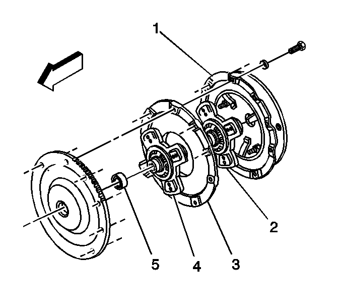
  1. Remove the transmission. Refer to Transmission Replacement.
  2. Remove the clutch pressure plate bolts and washers.
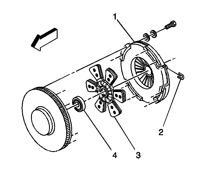
  3. Remove the clutch pressure plate (1).
  4. Remove the clutch driven plate (2).
  5. Remove the clutch intermediate plate (3).
  6. Remove the clutch front drive plate (4).
  7. Remove the clutch pilot bearing (5), if necessary.
  8. Remove the clutch brake, if necessary.

Inspection Procedure


    Object Number: 792690  Size: SH
  1. Remove any grease, dirt or oil from the flywheel surface.

  2. Object Number: 792691  Size: SH
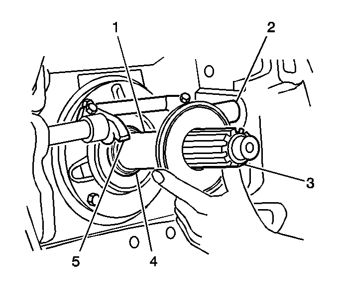
  3. Inspect the following items for wear:
  4. • Smooth area of the input shaft (1)
    • Cross-shafts and bushings (2)
    • Splines on the input shaft (3)
    • Release yoke fingers (5)

    Object Number: 792692  Size: SH
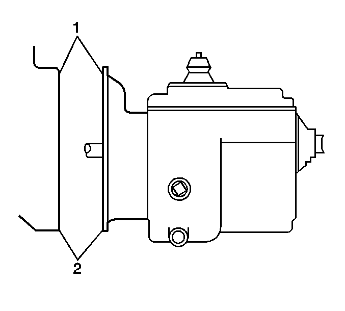
  5. Inspect the mating surfaces of the engine and bellhousing (1, 2), replace as necessary.

Installation Procedure


    Object Number: 792948  Size: SH
  1. Install the clutch pilot bearing, if necessary.
  2. Important: Ensure that the side marked "Flywheel Side" faces the flywheel.

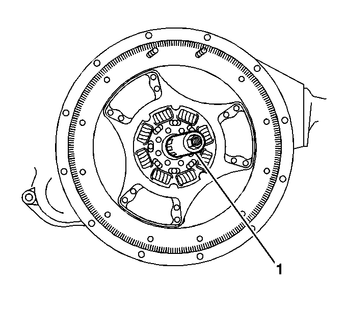
  3. Install the clutch driven rear plate by inserting the J-35989 or J-45274 (1) through the plate splines and into the pilot shaft.
  4. Object Number: 792952  Size: SH
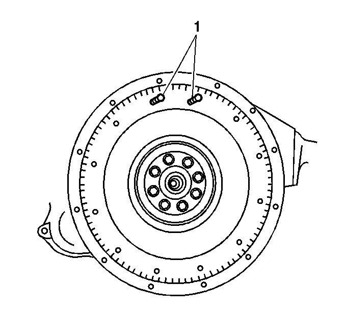
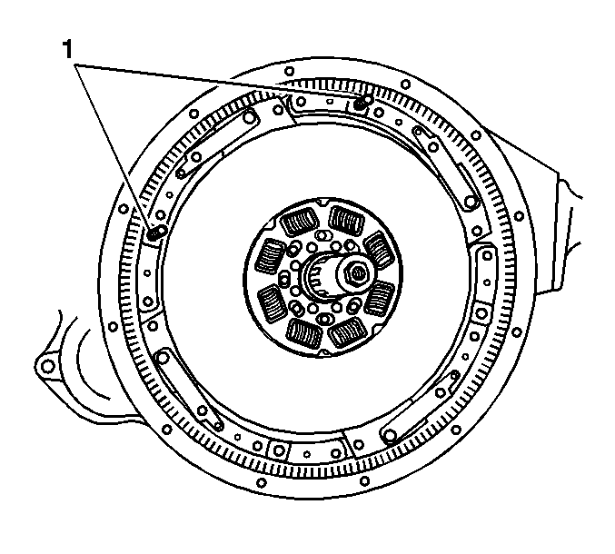
  5. Install two 3/8 x 16 x 3 inch long guide studs (1).
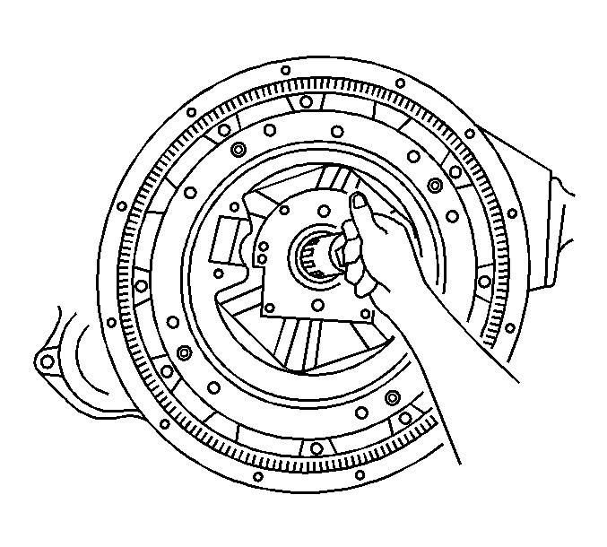
  6. Important: Ensure that the side marked "Pressure Plate Side" is facing the pressure plate.

  7. Install the clutch intermediate plate over the studs and forward until the plate touches the flywheel.
  8. Object Number: 792953  Size: SH
  9. Remove the J-35989 or J-45274 .
  10. Important: Ensure that the side marked "Pressure Plate Side" is facing the pressure plate.

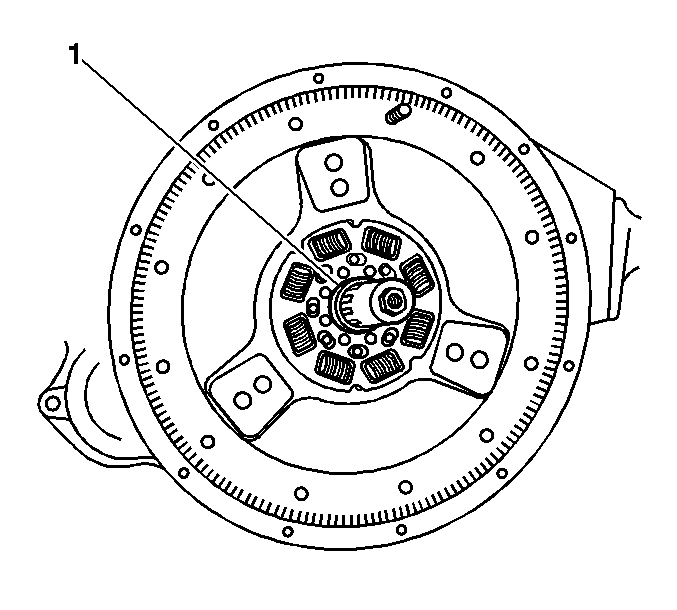
  11. Install the J-35989 or J-45274 through the splines of the clutch driven rear plate, and insert the J-35989 or J-45274 with the rear plate into the pilot bearing.
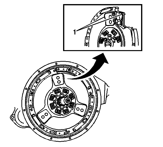
  12. Ensure that the ceramic buttons (1) align with each other as closely as possible, in order to aid the function of the positive roll pins.
  13. Object Number: 792958  Size: SH
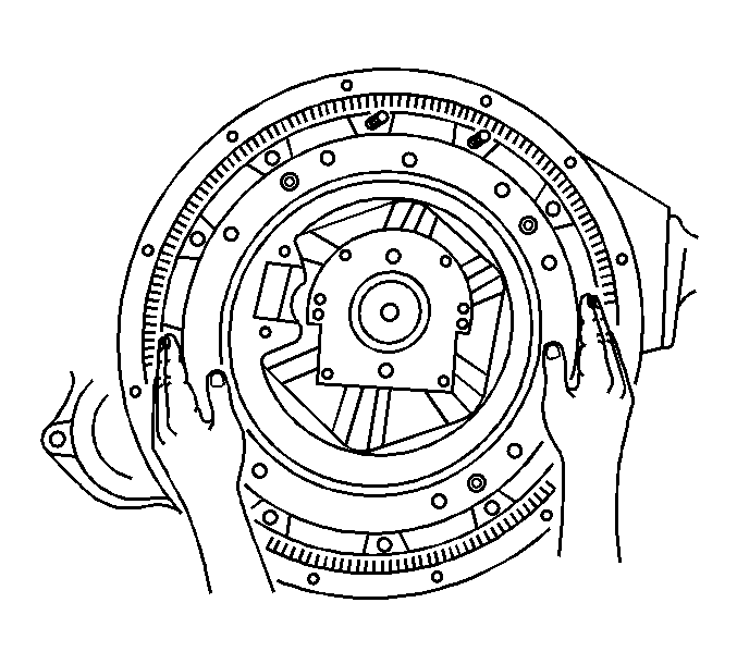
  14. Slide the pressure plate over both the guide studs and the J-35989 or J-45274 , until it rest against the intermediate plate.
  15. Object Number: 803986  Size: SH
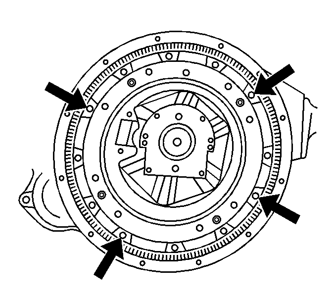
  16. Install 6 clutch pressure plate bolts, with washers, until finger tight.
  17. Remove the 2 guide studs, and install the final 2 clutch pressure plate bolts, with washers, finger tight.
  18. Notice: Refer to Fastener Notice in the Preface section.

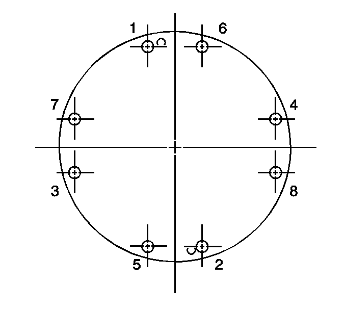
  19. Tighten the clutch pressure plate bolts, in the sequence shown.
  20. Tighten

    1. Tighten the clutch pressure plate bolts a first pass to 10 N·m (7 lb ft).
    2. Tighten the clutch pressure plate bolts a final pass to 54 N·m (40 lb ft).
  21. Remove the J-35989 or J-45274 .

  22. Object Number: 792959  Size: SH
  23. Using a hammer and a flat nose punch, lightly tap the 4 roll pins through the access holes, as shown, of the clutch cover.
  24. Ensure that the roll pins are against the flywheel. This will allow an equal gap on all sides of the intermediate plate during clutch disengagement.
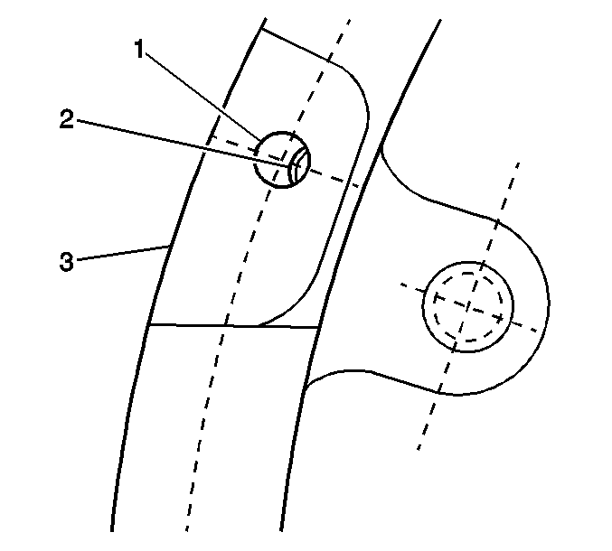
  25. Object Number: 792962  Size: SH

    Important: The roll pins may be damaged of struck with excessive force.

  26. Only a small portion of the roll pin (2) will be visible through the access hole (1) of the pressure plate (3).
  27. Important: Do not pull the release bearing back during the installation. Pulling the bearing back prior to transmission placement may cause the clutch to over adjust, an over adjusted clutch will not perform properly.

  28. If the clutch is inadvertently over adjusted, follow this procedure:
  29. 16.1. Pull the bearing away from the clutch until it comes to a stop and hold. The stop is internal if the transmission is not in place or the trans bearing cover/clutch brake is in place.
    16.2. Slide the wear indicating tab to the new position, very little force is required.
    16.3. Return the bearing toward the cover. The tab will stay in the new position.
    16.4. After the trans is in place reset the bearing position by stroking thorough the full range, 5 times.

    Important: Do not use the release lever to pull the transmission into its final position. Doing so may cause the clutch to over adjust. See over adjusted procedure above.

  30. After the transmission mounting bolts have been torqued, place a suitable tool over the release arm/shaft and completely release the clutch until the bearing comes to a complete stop. Stroke the bearing through its full range, 5 times. This process allows the clutch to adjust itself to the specific flywheel and transmission bearing cap position. Failure to do so will result in incorrect bearing position causing incorrect linkage set up.
  31. Install the transmission. Refer to Transmission Replacement.
Clutch Assembly Replacement Single Plate

Special Tools

    • J-35989 Clutch Alignment Arbor
    •  J-45274 Clutch Alignment Arbor

Removal Procedure


    Object Number: 792685  Size: SH
  1. Remove the transmission. Refer to Transmission Replacement.
  2. Remove the clutch pressure plate bolts and washers.
  3. Remove the clutch pressure plate (1).
  4. Remove the clutch driven plate (3).
  5. Remove the clutch pilot bearing (4), if necessary.
  6. Remove the clutch brake, if necessary.

Inspection Procedure


    Object Number: 792690  Size: SH
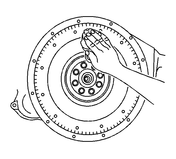
  1. Remove any grease, dirt or oil from the flywheel surface.

  2. Object Number: 792691  Size: SH
  3. Inspect the following items for wear:
  4. • Smooth area of the input shaft (1)
    • Cross-shafts and bushing (2)
    • Splines on the input shaft (3)
    • Release yoke fingers (5)
    • Clutch brake

    Object Number: 792692  Size: SH
  5. Inspect the mating surfaces of the engine and bellhousing (1, 2), replace as necessary.

Installation Procedure


    Object Number: 792693  Size: SH
  1. Install the clutch brake, if necessary with the plastic button towards the transmission.
  2. Install the clutch pilot bearing, if necessary.
  3. Install two 3/8 x 16 x 3 inch long (76 mm) guide studs (1) at the 11 o'clock and 1 o'clock positions on the flywheel.

  4. Object Number: 792694  Size: SH
  5. Apply lubrication to the hub splines.
  6. Install the J-35989 or J-45274 (1).
  7. Important: Ensure that the side marked "Pressure Plate Side" faces the pressure plate.

  8. Install the driven plate by sliding the plate over the J-35989 or J-45274 (1) splines and into the pilot bearing.
  9. Install the clutch pressure plate over the J-35989 or J-45274 (1) and the guide studs.

  10. Object Number: 803986  Size: SH
  11. Install 6 clutch pressure plate bolts, with washers, until finger tight.
  12. Notice: Refer to Fastener Notice in the Preface section.

  13. Remove the 2 guide studs, and install the final 2 clutch pressure plate bolts, with washers, finger tight.
  14. Tighten the clutch pressure plate bolts, in the sequence shown.
  15. Tighten

    1. Tighten the clutch pressure plate bolts a first pass to 10 N·m (7 lb ft).
    2. Tighten the clutch pressure plate bolts a final pass to 54 N·m (30 lb ft).

    Object Number: 792697  Size: SH
  16. Remove the J-35989 or J-45274 (1).
  17. Install the transmission. Refer to Transmission Replacement for the Medium Duty transmission.