For 1990-2009 cars only
Removal Procedure
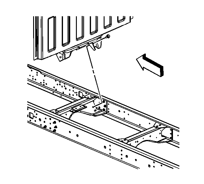
- Disengage the wiring harness connector retainer from the rear of the upper cab mount.
- Support the back of the cab.
- Remove the support bracket/cab mount assembly to the frame crossmember bolts.
- Raise the back of the cab slightly.
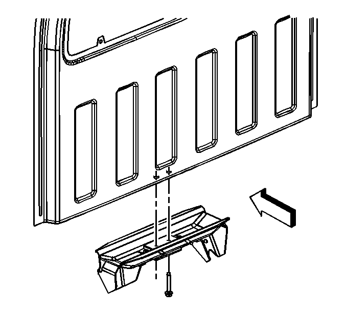
- Remove the support brackets/cab mount bolts.
- Remove the support brackets/cab mount assembly.
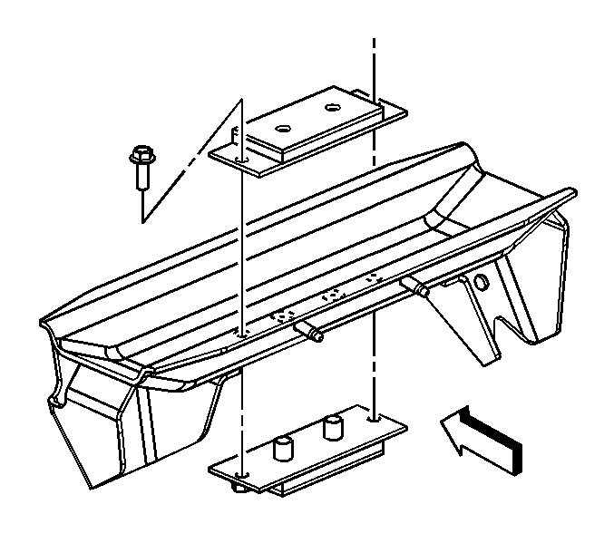
- Remove the mount to the cab support bracket bolts.
- Remove the mount from the cab support.

Important: Install lift straps or place a jack at each end of the rear cab sill. If jacks are used, place blocks of wood between the jacks and the sill.


Installation Procedure
- Install the mount to the cab support bracket.
- Install the outboard bolts.
- Install the support bracket/cab mount to the cab.
- Install the support brackets/cab mount bolts.
- Lower the back of the cab.
- Install the support bracket/cab mount assembly to the frame crossmember bolts.
- Engage the wiring harness connector retainer to the rear of the upper cab mount.

Important: Ensure that the word TOP on the mount is oriented properly.
Notice: Refer to Fastener Notice in the Preface section.
Tighten
Tighten the cab mount to cab support bracket bolts to 85 N·m (63 lb ft).

Tighten
Tighten the support bracket/cab mount to the cab bolts to 185 N·m (251 lb ft).

Tighten
Tighten the support bracket/cab mount assembly to the frame crossmember bolts to 260 N·m (192 lb ft).
