GM Service Manual Online
For 1990-2009 cars only

Removal Procedure


    Object Number: 1866475  Size: SH
  1. Remove the engine cover. Refer to Engine Cover Replacement.
  2. Remove the air cleaner. Refer to Air Cleaner Assembly Replacement.
  3. Drain the cooling system. Refer to Cooling System Draining and Filling.
  4. Remove the positive crankcase ventilation (PCV) pipe. Refer to Positive Crankcase Ventilation Hose/Pipe/Tube Replacement.
  5. Remove the intake manifold tube. Refer to Intake Manifold Tube Replacement.
  6. Remove the right side exhaust pipe. Refer to Exhaust Pipe Replacement - Right Side
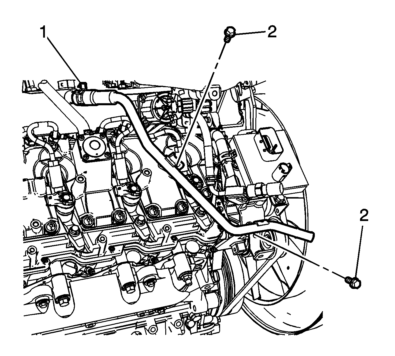
  7. Reposition the heater pipe to exhaust gas recirculation (EGR) valve cooler hose clamp (1).
  8. Remove the heater pipe bolts (2).
  9. Disconnect the heater pipe from the EGR valve cooler hose, and reposition the heater pipe out of the way.

  10. Object Number: 1867243  Size: SH
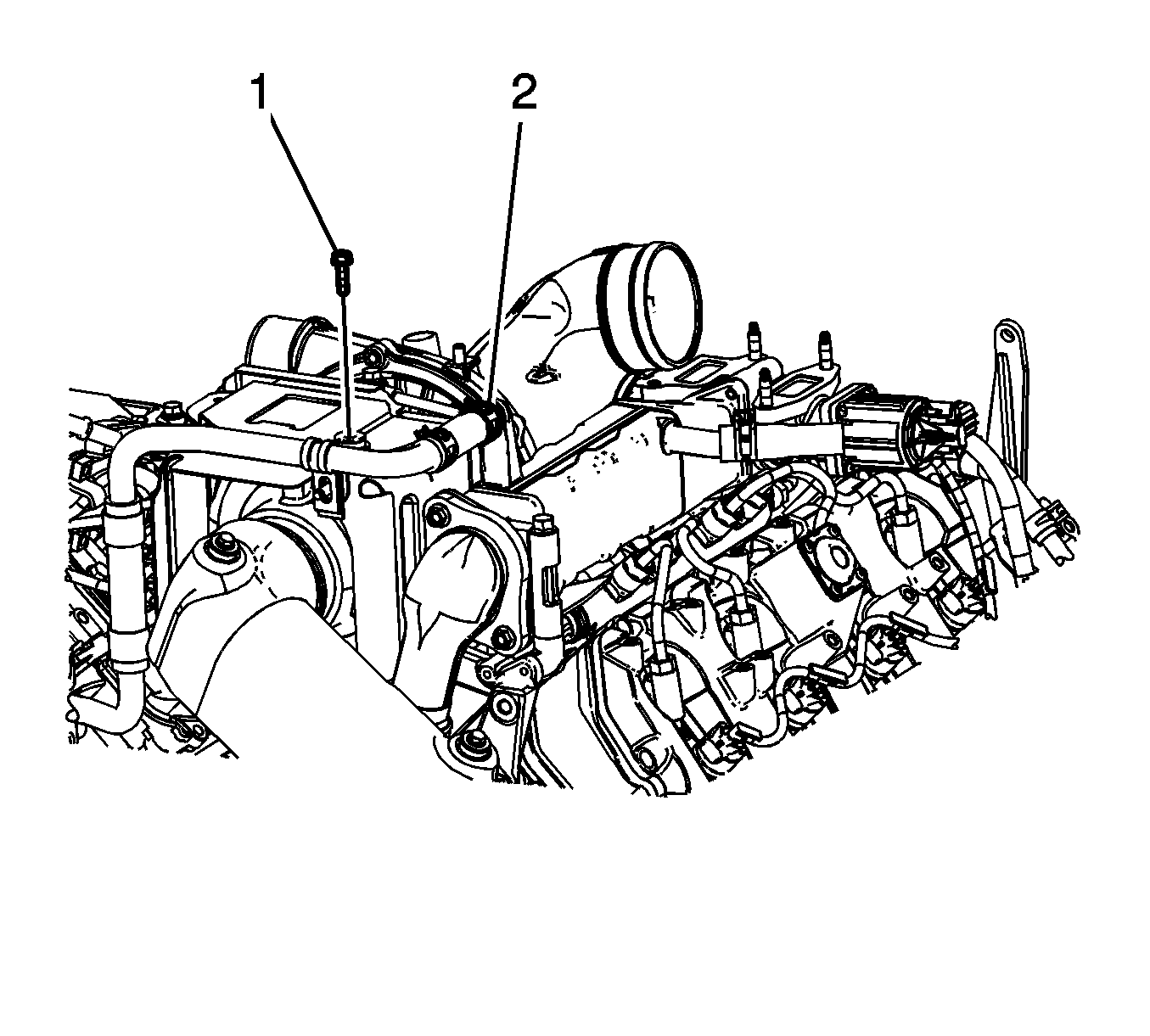
  11. Reposition the EGR valve cooler hose clamp (2).
  12. Remove the EGR valve cooler hose clamp nut (1).
  13. Reposition the EGR valve cooler hose/pipe out of the way.

  14. Object Number: 1864640  Size: SH
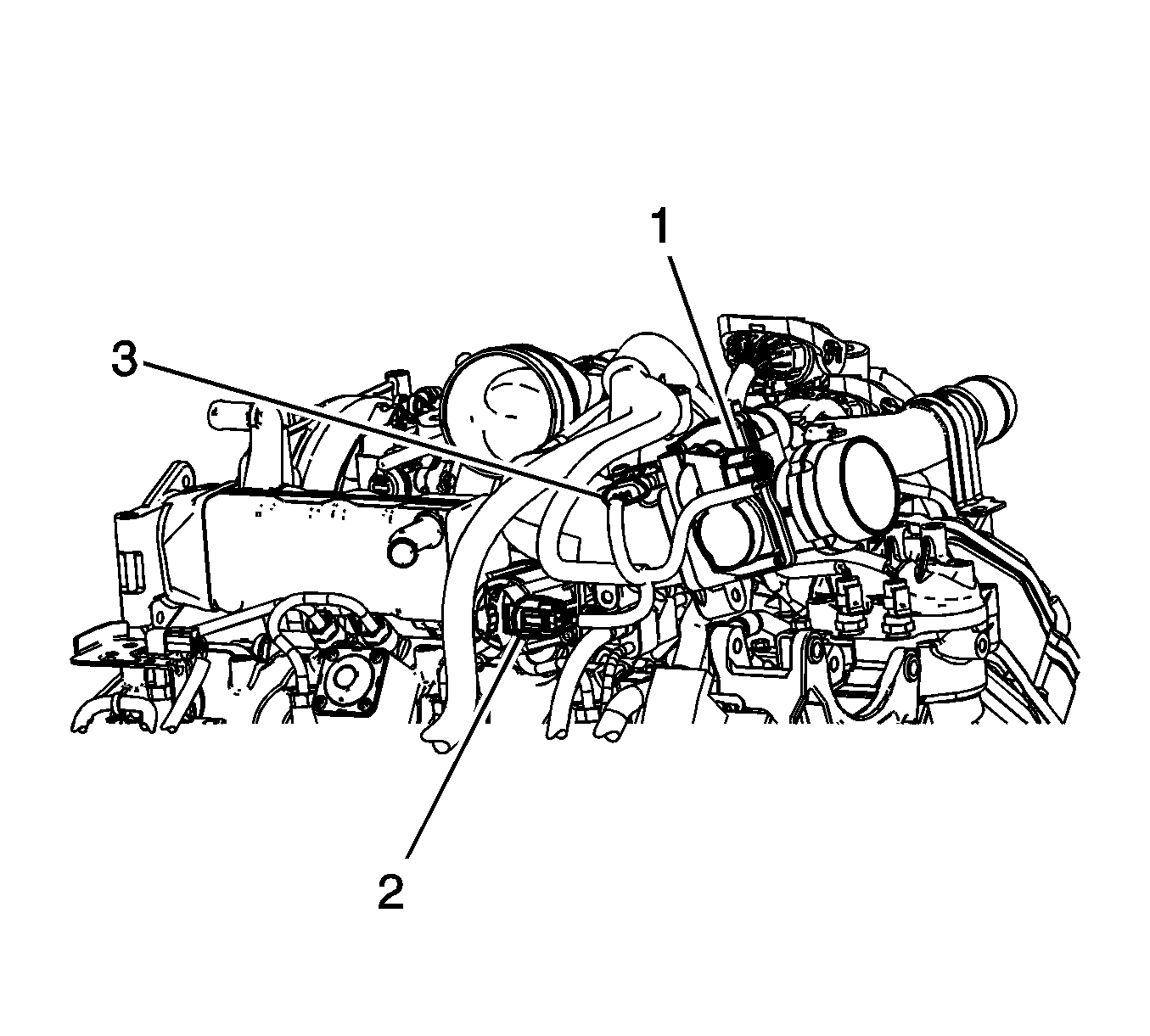
  15. Disconnect the engine wiring harness electrical connector (2) from the EGR valve.

  16. Object Number: 1867247  Size: SH
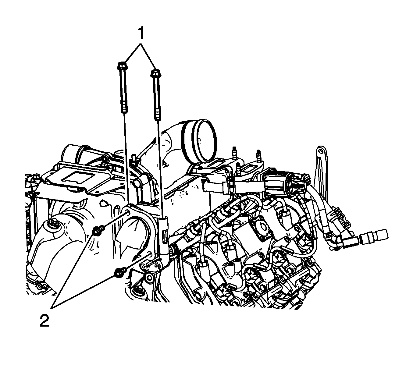
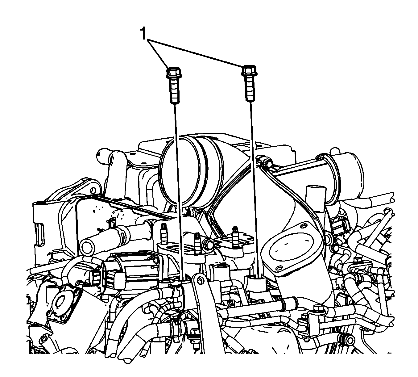
  17. Remove the EGR valve cooler rear bolts (1).
  18. Remove the right exhaust pipe to EGR valve cooler nuts (2).

  19. Object Number: 1867249  Size: SH
  20. Remove the EGR valve cooler front bolts (1).

  21. Object Number: 1998504  Size: SH
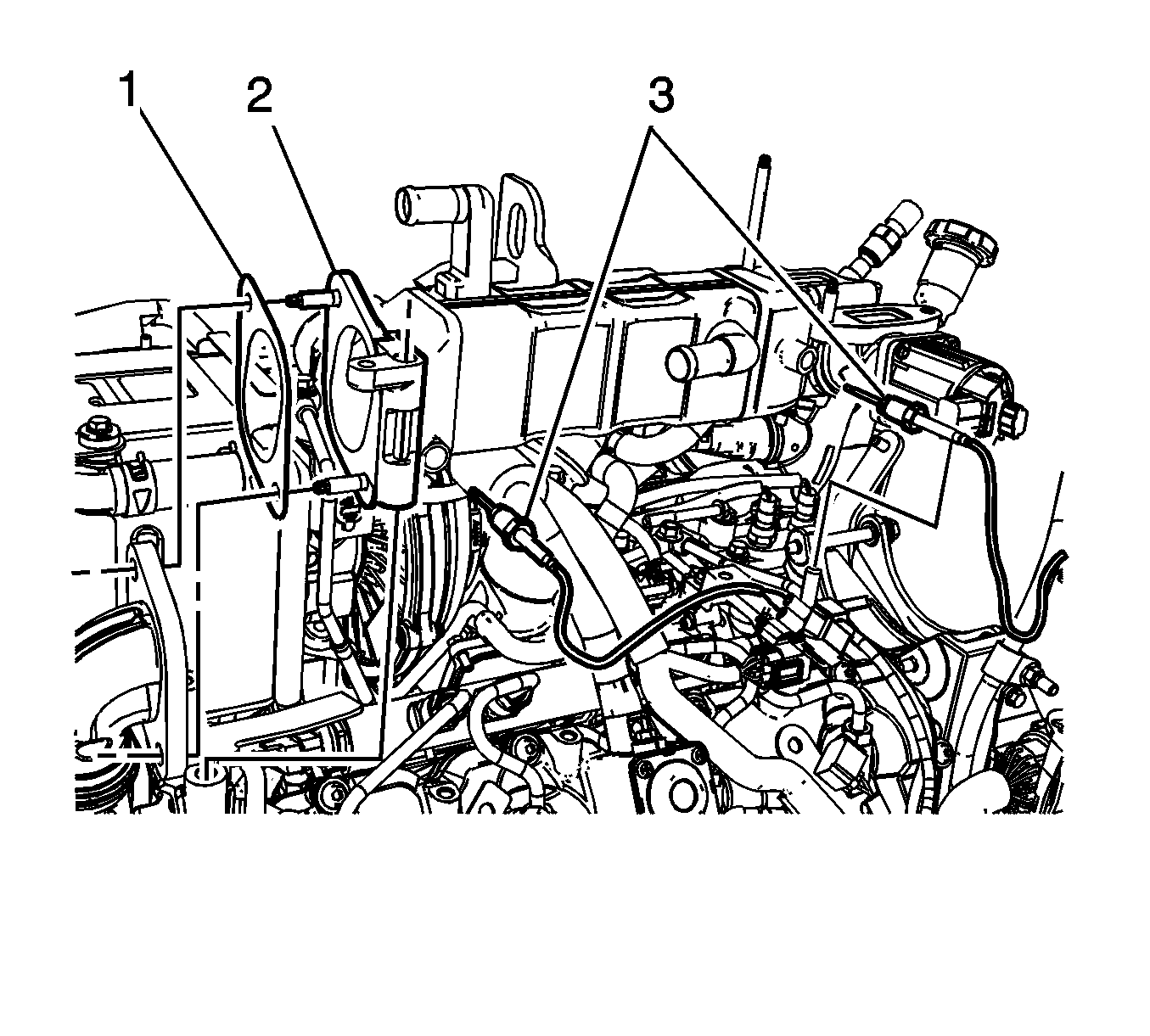
  22. Remove the EGR valve temperature sensors (3). Refer to Exhaust Gas Recirculation Valve Temperature Sensor Replacement - Position 1 and Exhaust Gas Recirculation Valve Temperature Sensor Replacement - Position 2.
  23. Remove the EGR valve cooler (2).
  24. Remove and discard the EGR valve cooler inlet gasket (1).

  25. Object Number: 1867255  Size: SH
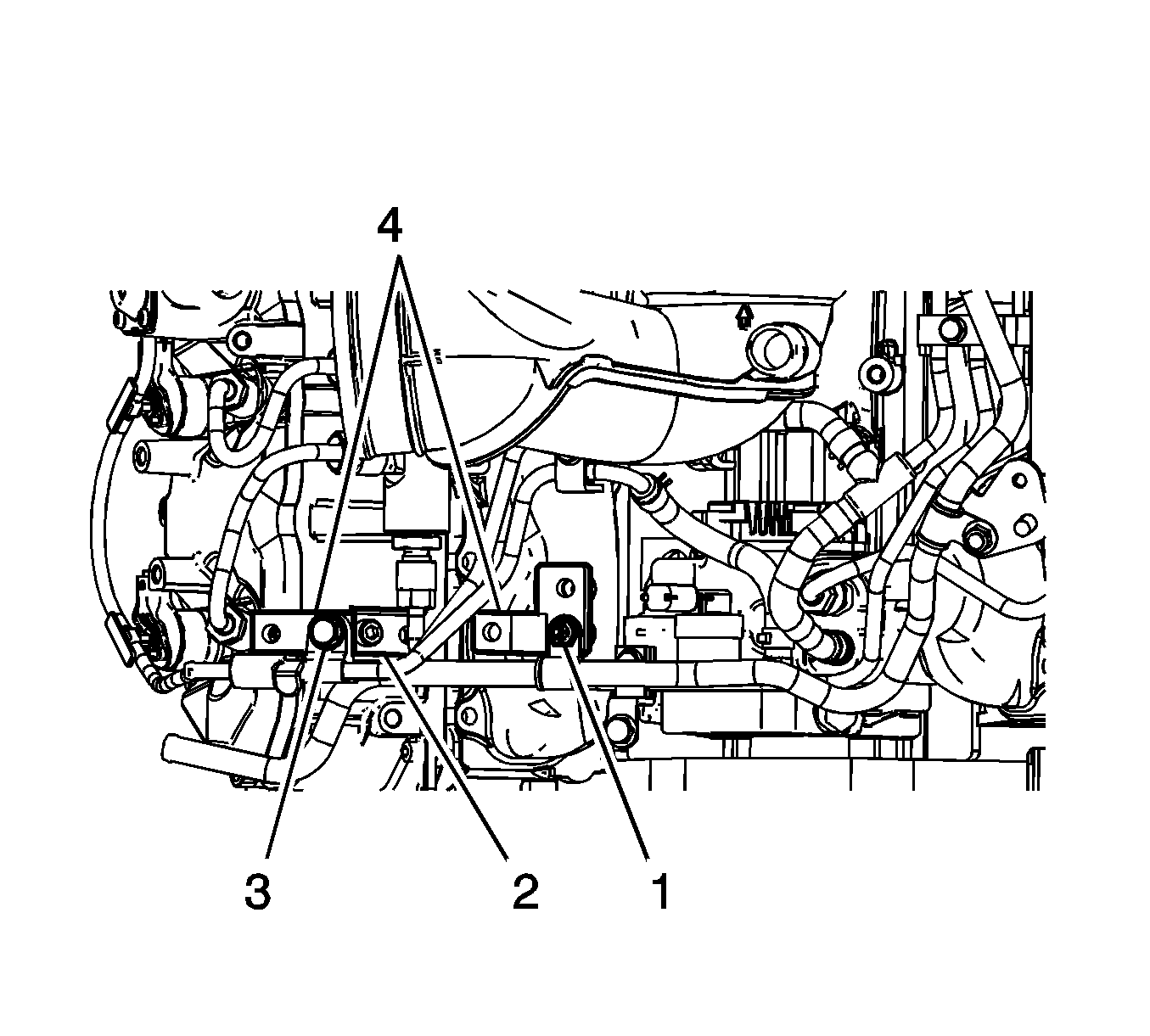
  26. If necessary, perform the following steps in order to remove the EGR brackets:
  27. 20.1. Remove the fuel injection fuel feed manifold bolt (3).
    20.2. Remove the fuel feed pipe nut (1) and reposition the clip.
    20.3. Remove the EGR bracket bolt (2).
    20.4. Remove the EGR brackets (4).

    Object Number: 1867258  Size: SH
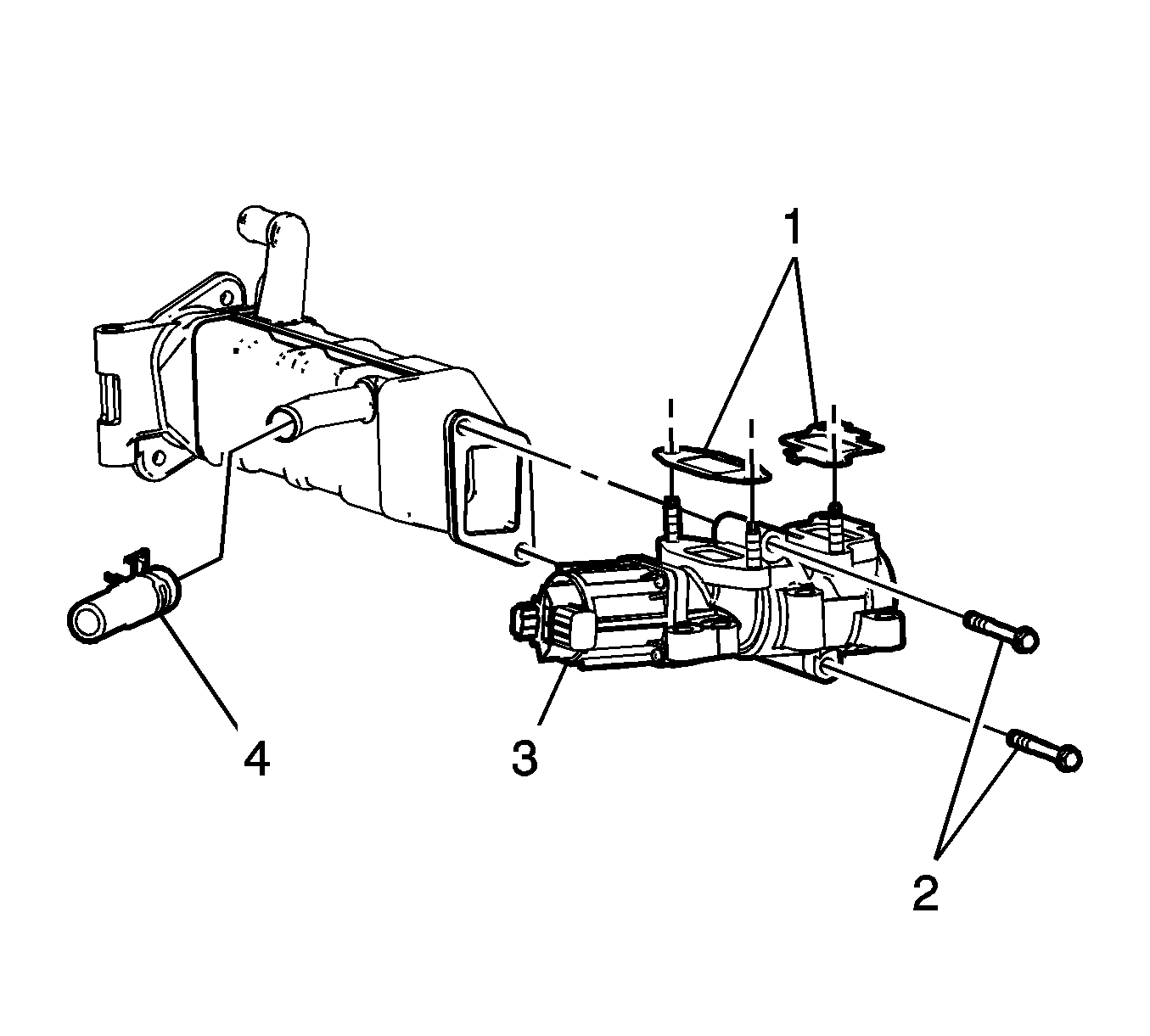
  28. If replacing the EGR valve cooler, perform the following steps:
  29. 21.1. Reposition the EGR valve cooler hose clamp and remove the hose (4).
    21.2. Remove the EGR valve bolts (2).
    21.3. Remove the EGR valve (3).
    21.4. Remove and discard the EGR valve gaskets (1).

Installation Procedure


    Object Number: 1867258  Size: SH
  1. If the EGR valve cooler was replaced, perform the following steps:
  2. 1.1. Position the EGR valve (3) to the cooler.

    Caution: Refer to Fastener Caution in the Preface section.

    1.2. Install the EGR valve bolts (2).

    Tighten
    Tighten the bolts to 20 N·m (15 lb ft).

    1.3. Install the EGR valve cooler hose (4) and position the hose clamp.
    1.4. Install NEW EGR valve gaskets (1).

    Object Number: 1867255  Size: SH
  3. If necessary, perform the following steps in order to install the EGR brackets:
  4. 2.1. Position the EGR brackets (4).
    2.2. Install the EGR bracket bolt (2).

    Tighten
    Tighten the bolt to 25 N·m (18 lb ft).
    2.3.  Position the clip and install the fuel feed pipe nut (1).

    Tighten
    Tighten the nut to 25 N·m (18 lb ft).

    2.4. Install the fuel injection fuel feed manifold bolt (3).

    Tighten
    Tighten the bolt to 25 N·m (18 lb ft).


    Object Number: 1998504  Size: SH
  5. Position a NEW EGR valve cooler inlet gasket (1) to the EGR valve cooler.
  6. Position the EGR valve cooler (2) to the engine.
  7. Install the EGR valve temperature sensors (3). Refer to Exhaust Gas Recirculation Valve Temperature Sensor Replacement - Position 1 and Exhaust Gas Recirculation Valve Temperature Sensor Replacement - Position 2.
  8. Object Number: 1867247  Size: SH
  9. Install the right exhaust pipe to EGR valve cooler bolts (2).
  10. Tighten
    Tighten the bolts to 53 N·m (39 lb ft).

  11. Install the EGR valve cooler rear bolts (1).
  12. Tighten
    Tighten the bolts to 25 N·m (18 lb ft).

    Object Number: 1867249  Size: SH
  13. Install the EGR valve cooler front bolts (1).
  14. Tighten
    Tighten the bolts to 25 N·m (18 lb ft).

    Object Number: 1864640  Size: SH
  15. Connect the engine wiring harness electrical connector (2) to the EGR valve.
  16. Object Number: 1867243  Size: SH
  17. Position the EGR valve cooler hose/pipe.
  18. Position the EGR valve cooler hose clamp (2).
  19. Install the EGR valve cooler hose clamp nut (1).
  20. Tighten
    Tighten the bolt to 9 N·m (80 lb in).

    Object Number: 1866475  Size: SH
  21. Position and connect the heater pipe the EGR valve cooler hose.
  22. Install the heater pipe bolts (2).
  23. Tighten
    Tighten the bolts to 25 N·m (18 lb ft).

  24. Position the heater pipe to EGR valve cooler hose clamp (1).
  25. Install the intake manifold tube. Refer to Intake Manifold Tube Replacement.
  26. Install the right exhaust pipe. Refer to Exhaust Pipe Replacement - Right Side
  27. Install the PCV pipe. Refer to Positive Crankcase Ventilation Hose/Pipe/Tube Replacement.
  28. Install the air cleaner. Refer to Air Cleaner Assembly Replacement.
  29. Fill the cooling system. Refer to Cooling System Draining and Filling.
  30. Install the engine cover. Refer to Engine Cover Replacement.