Tire Dismounting and Mounting Tubeless Tire
Demounting Procedure
Warning: Servicing of tires mounted on multi-piece rims requires proper tools, safety equipment, and specialized training. Severe injuries can result from improper servicing techniques. It is recommended
that tires on multi-piece rims be serviced only by competent personnel with proper equipment. Be careful not to drop wheel and tire assemblies on your hands and feet. Lift properly, using your legs as well as your body. Wheels and tires are heavy and can cause
injury if not handled correctly.
Warning: Use of eye goggles is necessary to prevent personal injury.
Caution: Wheel hub flanges, wheel studs, and stud nuts should be free of rust, lubricants, dirt, and finish color paint on all contact surfaces to ensure proper torque retention.
- Completely deflate the tire prior to demounting. If the rim is damaged, deflate the tire prior to removal of the tire and rim assembly from the vehicle. Reduce the pressure by pushing in the valve stem, or remove the entire
core. Keep your eyes away from the valve.
Note: Do not use a hammer when breaking the tire beads.
- With the tire assembly lying flat, break the bead seat of both beads with a bead breaking tool.
- Apply a proper tire lubricant such as Frey Lube II® lubricant or equivalent to the following areas:
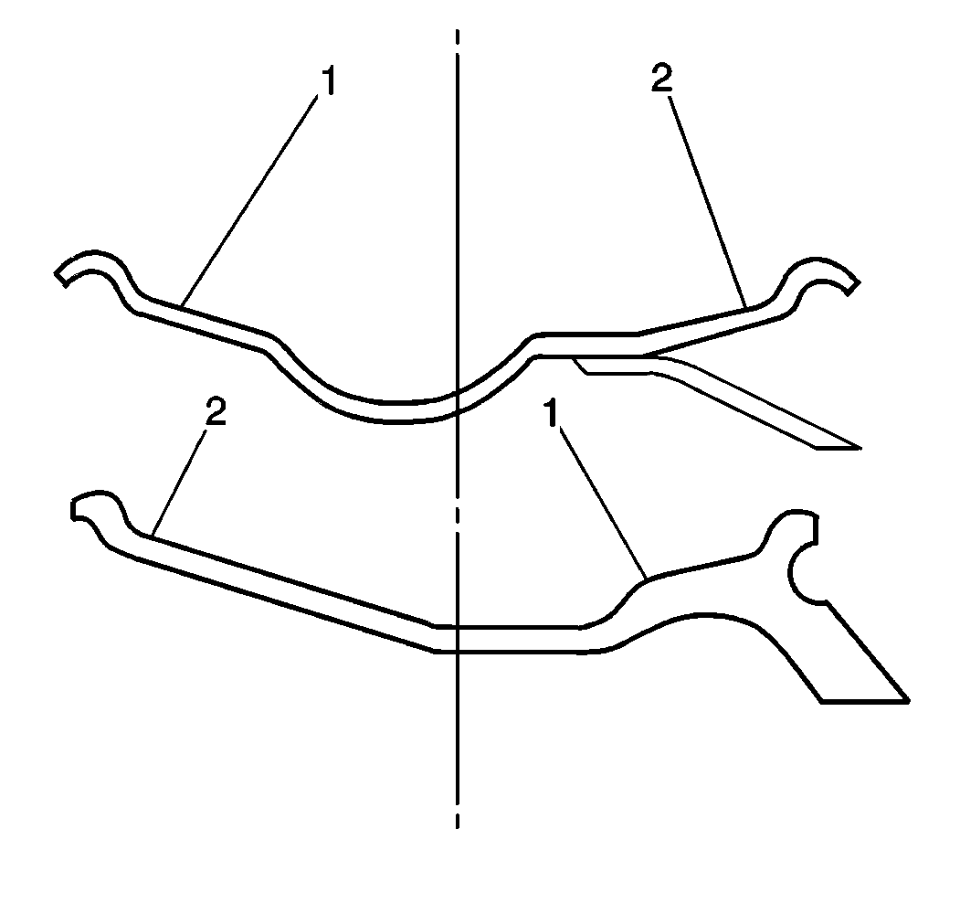
Note: Verify that the flange with the tapered ledge (1) that has the shortest span to the drop center is facing up.
- Beginning at the valve, remove the tire using tire irons designed for this purpose:
| • | Starting at the valve will minimize the chances of damaging the bead. |
| • | At any given time, you will not be working on some areas of the bead. Always attempt to retain these areas in the full depth of the drop center cavity. |
Note: Always replace the valve core when you replace the tires.
- Remove the following components from the rim:
Warning: To avoid eye injury, use approved safety lenses, goggles, or face shield when using buffing and cleaning equipment.
- Clean the rim of the following materials:
- When the tires are mounted on dirty or corroded rims, or when the tires are not properly centered on the rims, then the tire bead may bind on the rim and refuse to seat. Replace the rims that are corroded and weakened:
| • | Remove surface rust and other foreign matter from the rim. |
| • | Verify that the rim flanges and the bead ledge areas, especially the hump and the radius, are smooth and clean. |
| • | Remove any dried material using a wire brush: |
| - | Tire mounting lubricant |
| • | If the steel wheels show any bare metal, paint the wheels with a good grade of aluminum paint or equivalent. This will prevent rust. |
- Inspect the rim for the following conditions. If the rim is damaged, replace the rim.
Mounting Procedure
Warning: Use of eye goggles is necessary to prevent personal injury.
Warning: Only use mounting equipment tools specifically designed for tire mounting. Do not use improvised tools. Failure to observe this precaution could cause serious injury to you or other personnel
in the area.
Caution: When mounting the tires, use an approved tire mounting lubricant. DO NOT use silicon or corrosive base compounds to lubricate the tire bead and the wheel rim. A silicon base compound can cause
the tire to slip on the rim. A corrosive type compound can cause tire or rim deterioration.
Note: Use only proper size rims and do not exceed the recommended air pressures as specified on the vehicle certification label.
- Use the correct size tires and rims.

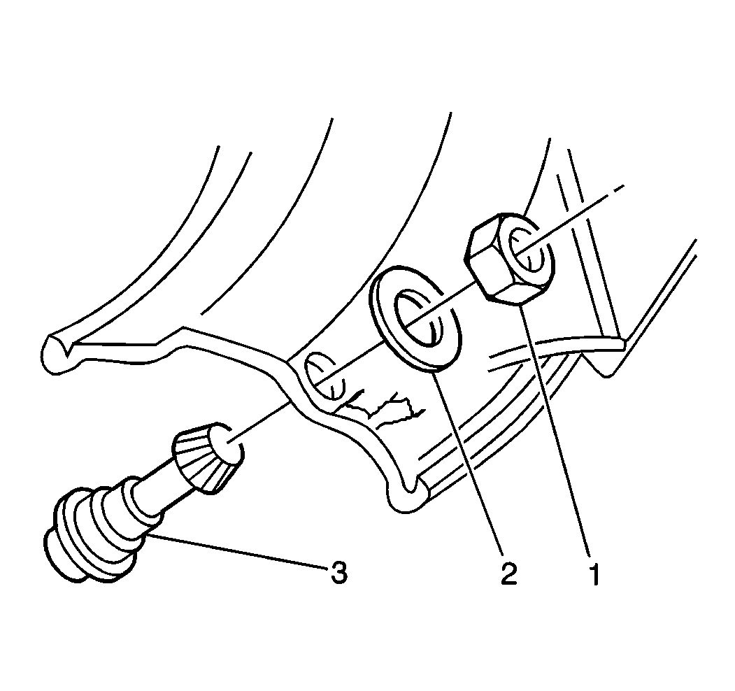
- Place the valve stem (3) with a rubber washer (2) through the valve hole from the tire side of the rim.
Caution: Refer to Fastener Caution in the Preface section.
- Screw on the valve nut (1) from the opposite side. Center the rubber bushing and the metal collar and the nut so that these parts fit snugly in the valve hole.
Tighten
Tighten the nut to 5 N·m (44 lb in).
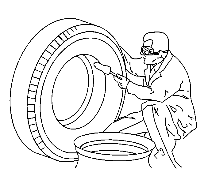
- Lubricate the following areas. Use an approved tire mounting compound such as Ru-Glyde®, Frey Lube II® or an equivalent.

Note: Do not use a hammer when installing the tire onto the rim.
- With the short side (1) facing up, lay the tire over the rim at the valve side. Work the tire on with the proper tubeless tire tools. Use the well in the drop center to its fullest extent.
Warning: Be careful not to drop tire and wheel assemblies on your hands and feet. Lift properly, using your legs as well as your body. Tires and wheels are heavy and can cause injury if not handled correctly.
Warning: Allowing pressure to continue to build up within a tire in an attempt to seat the bead is a dangerous practice that can result in a broken tire bead and possible serious injury to the technician.
Note:
| • | Use only dry air for tire inflation. Use a moisture trap on the air lines leading from the air compressor. |
| • | Do NOT overload the tires. Verify that the load and vehicle weights do not exceed the rated load of the tires. Rims are designed to sustain the maximum rated load of the maximum tire size recommended for that rim. For the recommended rated load and
tire size, refer to
Vehicle Certification Label. |
| • | Do NOT exceed the maximum inflation pressures. Inflation pressures are determined by the size and the ply rating of the tire. Refer to the manufacturers specification for proper inflation. Keep equal inflation in both tires of a dual assembly so
that the weight is equally distributed. |
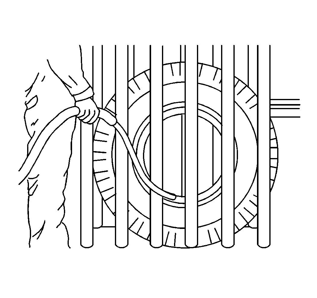
- Inflate the tire in a safety cage using an extension hose equipped with an air gage and a locking chuck. Inspect for proper bead seating by comparing the design elements on the circumference of the tire and at the top of the rim flange. These design elements
should be equally spaced around the tire.
Tire Dismounting and Mounting Tube-Type Tire
Demounting Procedure
Warning: Servicing of tires mounted on multi-piece rims requires proper tools, safety equipment, and specialized training. Severe injuries can result from improper servicing techniques. It is recommended
that tires on multi-piece rims be serviced only by competent personnel with proper equipment. Be careful not to drop wheel and tire assemblies on your hands and feet. Lift properly, using your legs as well as your body. Wheels and tires are heavy and can cause
injury if not handled correctly.
Warning: Use of eye goggles is necessary to prevent personal injury.
- Completely deflate the tire prior to demounting. If the rim is damaged, deflate the tire prior to removal of the tire and rim assembly from the vehicle. Reduce the pressure by pushing in the valve core, or remove the entire
core. Keep your eyes away from the valve. Do not gouge or nick the wheel or the rim when you remove the tire.
Warning: Failure to comply with these procedures may result in faulty positioning of the tire and/or rim parts, and cause the assembly to burst with explosive force, sufficient to cause serious physical
injury or death. Never mount or use damaged tires or rims.
Note: Before removing the tire and rim assembly from the truck, deflate the tire completely by removing the valve core. On duals, deflate both tires completely.
- Place the assembly on the floor, side ring up.
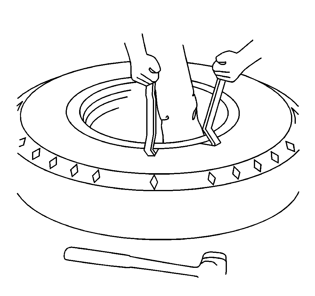
- Insert the hooked end of the tool between the side ring and the side wall of the tire. Pry the bead loose from the side ring, using a downward pressure on the rim tools.
- Continue to pry progressively around the tire until the bead is completely free from the side ring.
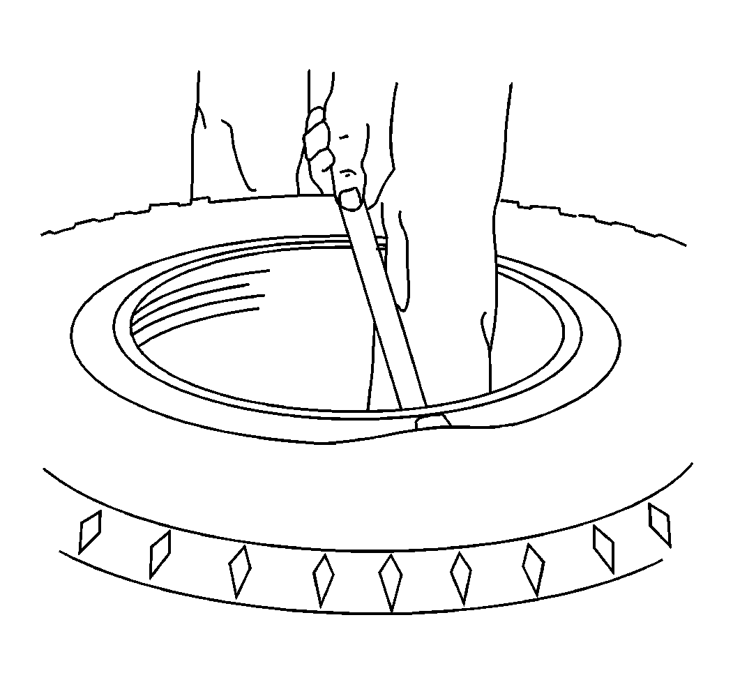
- With the side flange and the tire bead pushed down, insert the tapered end of the tool into the notch near the split in the lock ring. Push downward in order to pry the lock ring from the gutter groove of the rim base.
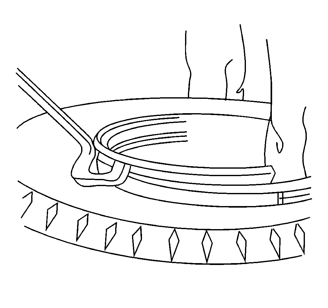
- Use the hooked end of the tool in order to complete the removal of the lock ring, progressively working around the tire.
- Turn the assembly over and unseat the second tire bead from the rim.
- Lift the rim from the tire. Remove the tube and the flap, if any, from the tire.
- Clean and inspect the rim and the parts. Replace the parts as necessary.
Mounting Procedure

- Verify that the rim flanges (1) and the bead ledge (2) areas, especially the hump and the radius are smooth and clean.
- Remove any dried material using a wire brush:
| • | Tire mounting lubricant |
- If the steel wheels show any bare metal, paint the wheels with a good grade of aluminum paint or equivalent. This will prevent rust.
Warning: Only use mounting equipment tools specifically designed for tire mounting. Do not use improvised tools. Failure to observe this precaution could cause serious injury to you or other personnel
in the area.
Warning: Be careful not to drop tire and wheel assemblies on your hands and feet. Lift properly, using your legs as well as your body. Tires and wheels are heavy and can cause injury if not handled correctly.
Warning: Allowing pressure to continue to build up within a tire in an attempt to seat the bead is a dangerous practice that can result in a broken tire bead and possible serious injury to the technician.
Caution: When mounting the tires, use an approved tire mounting lubricant. DO NOT use silicon or corrosive base compounds to lubricate the tire bead and the wheel rim. A silicon base compound can cause
the tire to slip on the rim. A corrosive type compound can cause tire or rim deterioration.
Note: Do not use rims, locking rings, or flanges that are out of shape, rusted, or broken. Do not use a ring or rim parts of a different manufacture than the rim, or of a different size or type than the rim.
Note: When tires are mounted on dirty or corroded rims, or when tires are not properly centered on the rims, the tire bead may bind on the rim and refuse to seat. A buildup of rust and foreign material in the rim gutter may prevent the
proper fitting of rings. Replace corroded and weakened parts.
- Whenever you mount a tube-type tire, observe the following:
| • | Replace damaged parts. Before mounting a tire and assembling the rim, inspect the rim part carefully for the following conditions: |
| • | Remove surface rust and other foreign matter. |
| • | Verify that the flange with the tapered ledge that has the shortest span to the drop center is facing up. |
| • | Use the correct size tires and rims. Use only proper size rims. Do not exceed the recommended air pressures. |
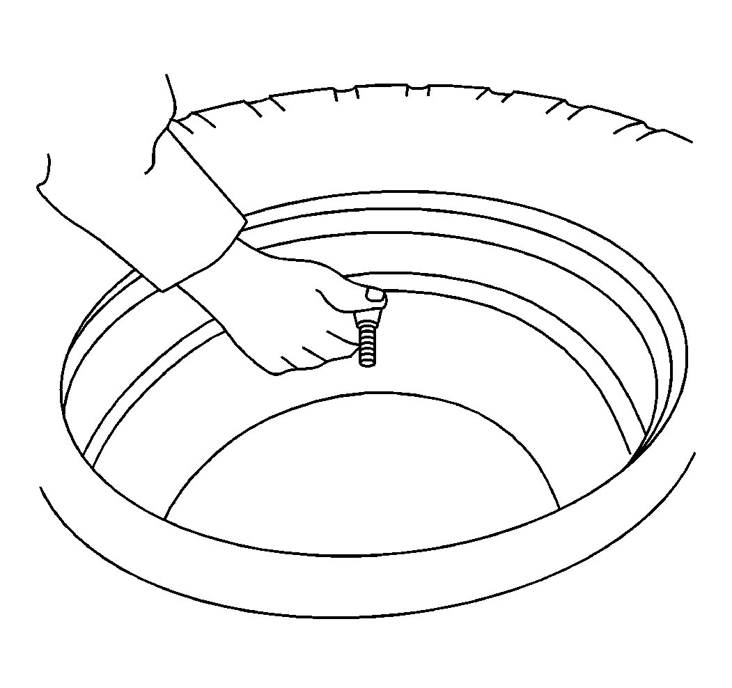
- Insert the tube into the tire and partially inflate the tire in order to round out the tube.
- Apply a rubber lubricant to the inside and outside surfaces of both beads. Apply a rubber lubricant to that portion of the tube that appears between the beads.
- Insert the flap and lubricate the flap.
- Lay the rim flat on the floor with the valve slot up.
- Align the valve with the rim valve slot. Place the tire onto the rim. Insert the valve through the valve slot.
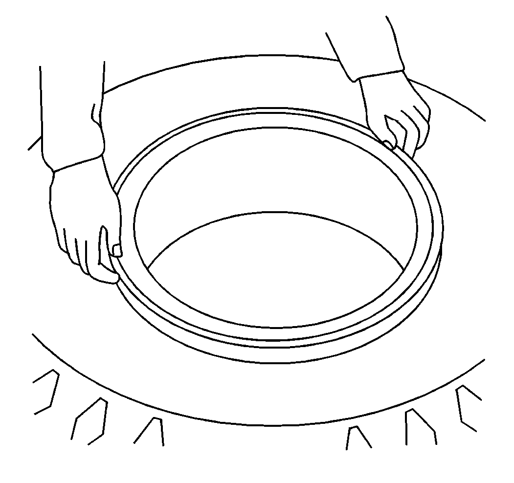
- Place the side flange on the rim base.
- Stand on the flange in order to position the flange below the gutter grooves in the rim base.
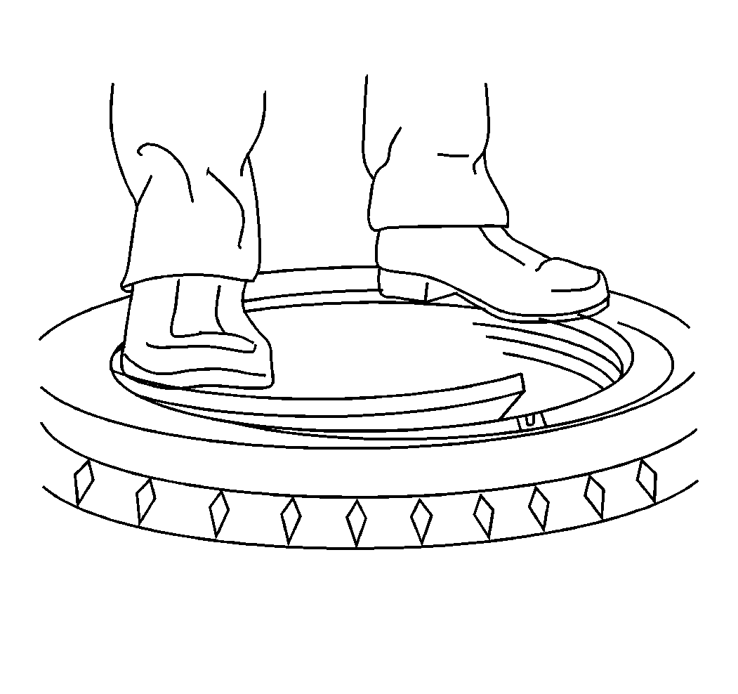
- Snap the leading end of the lock ring into the gutter groove of the rim base and progressively "walk" the lock into place.
- Verify that the lock ring is fully seated in the gutter groove.

- Place the tire in a safety cage.
- Inflate the tire to approximately 10 psi, using an extension hose which is equipped with an air gage and a clip-on air chuck.
- Verify that the lock-ring is engaged properly. If assembly is not proper, deflate the tire and correct the condition. NEVER hammer on an inflated or a partially inflated tire/rim assembly.
- If assembly is proper, continue to inflate the tire to its recommended inflation pressure.
- Verify that the beads are seated properly.
- Completely deflate the tire in order to prevent localized overstretching of the tube and the flap.
- Reinflate the tire to its recommended pressure.


