- Remove the differential side bearing shims. Refer to
Drive Pinion Bearings Replacement.
- Determine the pinion position shim and the pinion preload shims, if necessary. Refer to
Pinion Depth Adjustment.

- Install the differential side bearing without the side bearing shims by doing the following:
| 3.1. | In order to protect the differential case, install the
J 36597 in the case on the side opposite of the bearing installation. |
| 3.2. | Install the differential side bearing. |
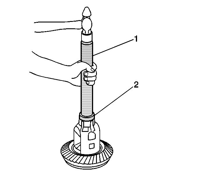
| 3.4. | Drive the differential side bearing into position using the
J 24430 or the
J 45900 and the
J 8092 . |
- Install the differential assembly into the axle housing.
- Move the differential assembly to the left until the left differential side bearing is against the left side bearing bore.
Note: Install the bearing caps into the same position from which each was removed.
- Install the left side bearing cap.
Caution: Refer to Fastener Caution in the Preface section.
- Install the left side bearing cap bolts and tighten the bearing cap bolts finger tight.
Do not tighten the bolts to specification at this time.
- While holding the differential assembly against the left side bearing bore, press the right side bearing cup against the right differential side bearing.
Note: In order to accurately measure the differential side bearing shim thickness, the differential side bearing cup must be evenly seated against the differential side bearing.

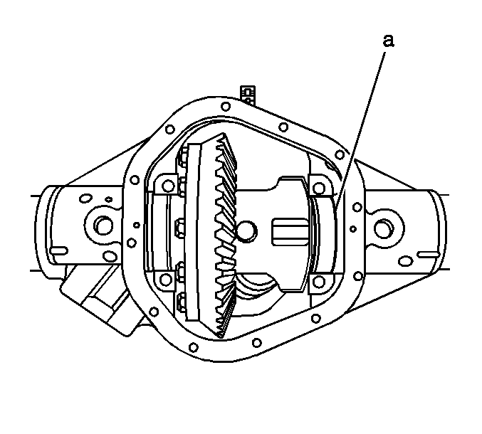
- Using a feeler gage, measure the distance between the right side bearing cup and the right side bearing bore. Use progressively larger feeler gage sizes until a moderate drag is felt. Repeat this step several times while rotating
the differential case in order to obtain a consistent reading.
This measurement, measurement a, is the total shim pack thickness for the differential assembly without preload.
Warning: To prevent personal injury and/or component damage, support the differential case when removing the case from the axle housing. If the case is not supported, the differential case could fall and
cause personal injury or damage to the differential case.
- Remove the left side bearing cap bolts.
- Remove the left side bearing cap.
- Install the right side bearing cap.
- Install the right side bearing cap bolts.
Tighten the bearing cap bolts finger tight. Do not tighten the bolts to specification at this time.
- While holding the differential assembly ring gear against the drive pinion, press the left side bearing cup against the left differential side bearing.
Note: In order to accurately measure the differential side bearing shim thickness, the differential side bearing cup must be evenly seated against the differential side bearing.

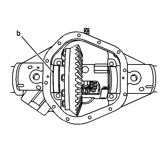
- Using a feeler gage, measure the distance between the left side bearing cup and the left side bearing bore. Use progressively larger feeler gage sizes until a moderate drag is felt. Repeat this step several times while re-positioning
the differential case in order to obtain a consistent reading.
This measurement, measurement b, is the left side shim thickness for the differential assembly without preload.
- In order to determine the right side shim thickness, subtract the left side measurement, measurement b, from the total shim measurement, measurement a.
This measurement is the thickness for the right side shim thickness without preload
or setting the initial backlash.
- Remove the right side bearing cap bolts.
- Remove the right side bearing cap.
- Remove the differential assembly.

- Remove the differential side bearings by performing the following steps:
| 20.2. | Remove the differential side bearings using the
J 45711 and a hydraulic press. |
- Add 0.25 mm (0.010 in) of shim thickness to the right side shim thickness measurement determined in step 16.
This additional amount will set the differential side bearing preload and the initial backlash.
Note: The number of shims required in order to equal the correct thickness may consist of one or more shims.
- Install the right side shim thickness onto the differential case.
Measure the shims one at a time. Add the measurements together in order to obtain the total thickness of the right side shim pack.

- Install the right differential side bearing with the side bearing shim thickness by doing the following:
| 23.1. | In order to protect the differential case, install the
J 8107-3 in the case on the side opposite of the bearing installation. |
| 23.2. | Place the differential side shim thickness on top of the differential case. |
| 23.3. | Place the differential side bearing on top of the differential case. |
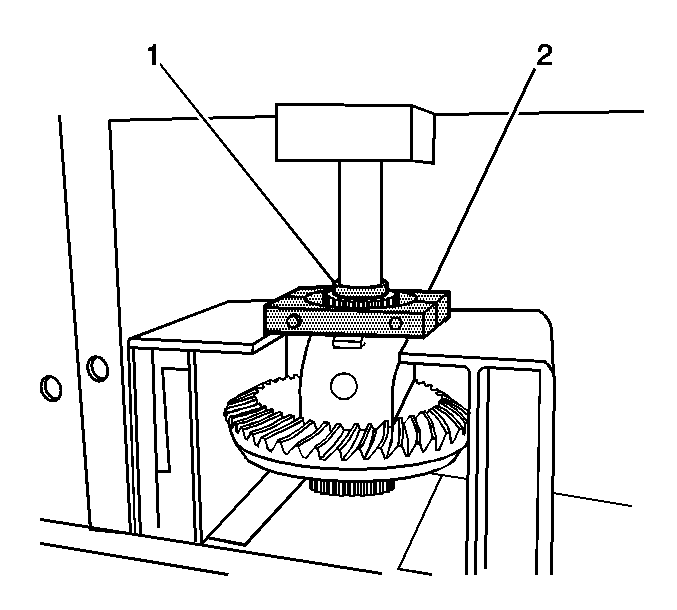
| 23.5. | Drive the differential side bearing into position using the
J 24430 or the
J 45900 and the
J 8092 . |
Note: The number of shims required in order to equal the correct thickness may consist of one or more shims.
- Install the left side bearing shim thickness and differential side bearing using the steps above.
- Install the differential assembly into the axle housing. Refer to
Differential Replacement.
The differential side bearing shims are available in the following sizes:


