| Table 1: | Accelerator Pedal Position (APP) Sensor |
| Table 2: | BARO Sensor |
| Table 3: | Boost Sensor |
| Table 4: | Camshaft Position (CMP) Sensor-Bottom |
| Table 5: | Camshaft Position (CMP) Sensor-Top |
| Table 6: | Clutch Switch |
| Table 7: | Coolant Level Switch |
| Table 8: | Cooling Fan Control |
| Table 9: | Engine Control Module (ECM) C1 |
| Table 10: | Engine Control Module (ECM) C2 |
| Table 11: | Engine Coolant Temperature (ECT) Sensor |
| Table 12: | Ether Solenoid |
| Table 13: | Fuel Injector 1 |
| Table 14: | Fuel Injector 2 |
| Table 15: | Fuel Injector 3 |
| Table 16: | Fuel Injector 4 |
| Table 17: | Fuel Injector 5 |
| Table 18: | Fuel Injector 6 |
| Table 19: | High Idle Switch |
| Table 20: | Intake Air (IA) Heater |
| Table 21: | Intake Air (IA) Heater Relay |
| Table 22: | Intake Air Temperature (IAT) Sensor |
| Table 23: | Suction Control Valve (SCV) |
| Table 24: | Trans Speed Sensor (Man) |
| Table 25: | Water in Fuel Sensor |
| |||||||
|---|---|---|---|---|---|---|---|
Connector Part Information |
| ||||||
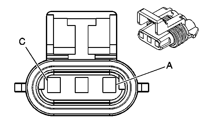
Pin | Wire Color | Circuit No. | Function | ||||
A | WH/BK | 1164 | 5-Volt Reference | ||||
B | BK/WH | 451 | Ground | ||||
C | D-BU | 1161 | APP Sensor 1 Signal | ||||
| |||||||
|---|---|---|---|---|---|---|---|
Connector Part Information |
| ||||||
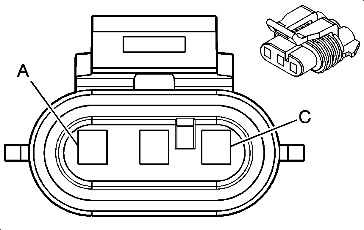
Pin | Wire Color | Circuit No. | Function | ||||
A | GN | G829 | Low Reference | ||||
B | GN | G849 | Baro Sensor Signal | ||||
C | WH | G828 | 5-Volt Reference | ||||

| |||||||
|---|---|---|---|---|---|---|---|
Connector Part Information |
| ||||||
Pin | Wire Color | Circuit No. | Function | ||||
A | GN | G829 | Low Reference | ||||
B | PK | A746 | Boost Pressure Sensor Signal | ||||
C | WH | G828 | 5-Volt Reference | ||||
| |||||||
|---|---|---|---|---|---|---|---|
Connector Part Information |
| ||||||
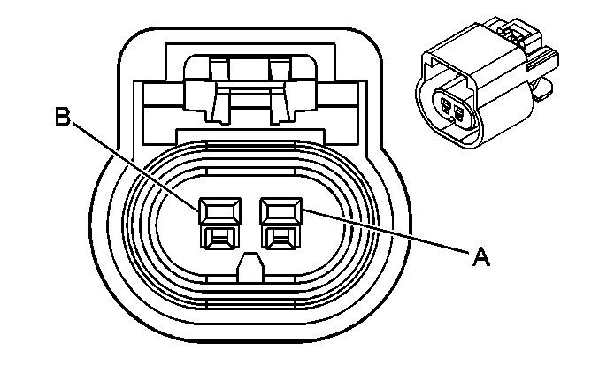
Pin | Wire Color | Circuit No. | Function | ||||
A | BU | E965 | Camshaft Sensor Signal-Bottom | ||||
B | BK | E966 | Low Reference | ||||

| |||||||
|---|---|---|---|---|---|---|---|
Connector Part Information |
| ||||||
Pin | Wire Color | Circuit No. | Function | ||||
A | BK | E963 | Camshaft Sensor Signal-Top | ||||
B | WH | E964 | Low Reference | ||||
| |||||||
|---|---|---|---|---|---|---|---|
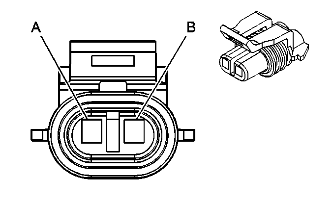
Connector Part Information |
| ||||||
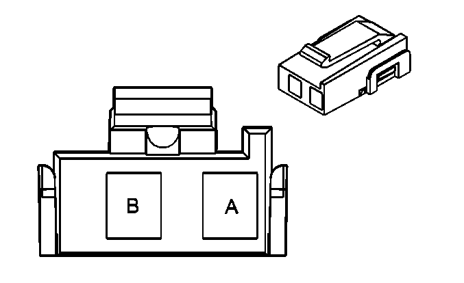
Pin | Wire Color | Circuit No. | Function | ||||
A | BN/WH | 379 | CPP Switch Signal | ||||
B | BN | 981 | Rear Floodlamp On Relay Control | ||||
| |||||||
|---|---|---|---|---|---|---|---|
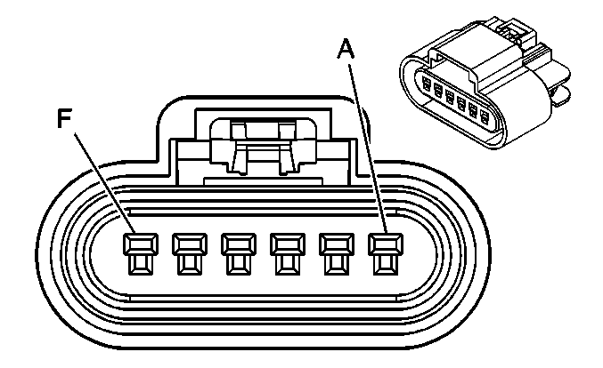
Connector Part Information |
| ||||||
Pin | Wire Color | Circuit No. | Function | ||||
A | L-GN | 1478 | Coolant Level Switch Signal | ||||
B | BK/WH | 451 | Ground | ||||
| |||||||
|---|---|---|---|---|---|---|---|
Connector Part Information |
| ||||||
Pin | Wire Color | Circuit No. | Function | ||||
A | BK/WH | 1120 | Clutch Coil Supply Voltage | ||||
B | GY | 2365 | Low Reference | ||||
C | D-BU | 2364 | Cooling Fan Speed Signal | ||||
D | PU | 719 | Low Reference | ||||
E | BK | 450 | Ground | ||||
F | -- | -- | Not Used | ||||
| |||||||
|---|---|---|---|---|---|---|---|
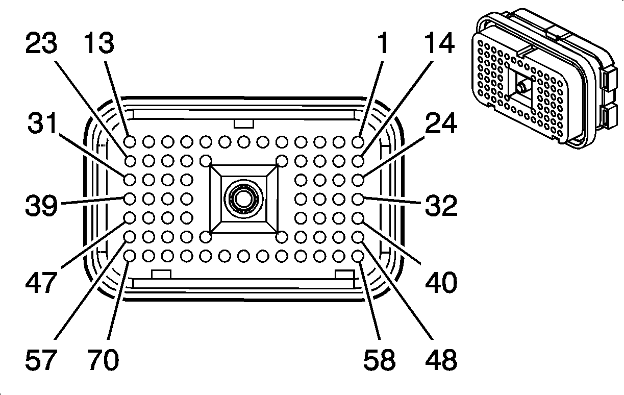
Connector Part Information |
| ||||||
Pin | Wire Color | Circuit No. | Function | ||||
1 | -- | -- | Not Used | ||||
2 | GY | 2365 | Low Reference | ||||
3 | BK | 470 | Low Reference | ||||
4 | WH/BK | 1164 | 5-Volt Reference | ||||
5 | BK/WH | 451 | Ground | ||||
6 | GY/BK | 1467 | Air Shift Switch Signal (Air Operated) | ||||
7 | L- BU | 494 | Engine Shut Off-Signal | ||||
8 | TN/BK | 1921 | SAE J1708 Serial Data A | ||||
9 | WH/BK | 1922 | SAE J1708 Serial Data B | ||||
10 | TN | 1997 | Headlamp Washer Pump Control | ||||
11 | BK/WH | 1120 | Engine Fan Clutch Control | ||||
12 | PU | 2656 | Exhaust Brake Control | ||||
13-14 | -- | -- | Not Used | ||||
15 | PU | 1589 | Fuel Level Sensor Signal - Primary | ||||
16 | L-GN | 2081 | Exhaust Brake Switch Relay | ||||
17 | -- | -- | Not Used | ||||
18 | PU | 719 | Low Reference & LG5 | ||||
19 | D-GN/WH | 2665 | PTO Enable | ||||
20 | -- | -- | Not Used | ||||
21 | RD | 2013 | High Idle Indicator Control | ||||
22 | BN/WH | 379 | CPP Switch Signal | ||||
23-25 | -- | -- | Not Used | ||||
26 | D-BU | 1936 | Fuel Level Sensor Signal - Secondary | ||||
27 | -- | -- | Not Used | ||||
28 | BN/WH | 419 | MIL Control | ||||
29 | -- | -- | Not Used | ||||
30 | YE | 32 | Instrument Panel Lamp Fuse Supply Voltage | ||||
31 | YE | 447 | Starter Relay Coil Control | ||||
32 | L-BU | 2221 | Signal High - Rear | ||||
33 | D-GN | 2222 | Signal Low - Rear | ||||
34 | D-GN | 2362 | CAN Serial Data Low | ||||
35 | D-BU | 84 | Cruise Control Set/Coast Switch Signal | ||||
36 | D-GN /WH | 817 | Vehicle Speed Signal | ||||
37 | -- | -- | Not Used | ||||
38 | WH | 121 | Engine Speed Signal | ||||
39 | -- | -- | Not Used | ||||
40 | D-GN | 534 | High Idle Switch Signal | ||||
41-43 | -- | -- | Not Used | ||||
44 | GR/BK | 87 | Cruise Control Resume/Accel Switch Signal | ||||
45 | BN | 86 | Cruise Control Release Signal | ||||
46-48 | -- | -- | Not Used | ||||
49 | L-GN | 1478 | Coolant Level Switch Signal | ||||
50 | YE | 2361 | CAN Serial Data High | ||||
51 | -- | -- | Not Used | ||||
52 | OG | 1540 | Battery Positive Voltage | ||||
53 | OG | 1540 | Battery Positive Voltage | ||||
54-55 | -- | -- | Not Used | ||||
56 | L-GN | 488 | PTO On Switch-Signal | ||||
57 | -- | -- | Not Used | ||||
58 | PU | 2663 | PTO Set | ||||
59 | GY | 397 | Cruise Control On Switch Signal | ||||
60 | TN | 2664 | Coolant Fan Control | ||||
61 | -- | -- | Not Used | ||||
62 | D-GN/WH | 459 | A/C Compressor Clutch Relay Control | ||||
63 | -- | -- | Not Used | ||||
64 | L-BU | 1320 | CHMSL Supply Voltage/Stop Lamp Supply Voltage | ||||
65 | BK/WH | 251 | Ground | ||||
66 | D-BU | 1161 | APP Sensor 1 Signal | ||||
67 | BK/WH | 251 | Ground | ||||
68-69 | -- | -- | Not Used | ||||
70 | PK | 439 | Ignition 1 Voltage | ||||

| |||||||
|---|---|---|---|---|---|---|---|
Connector Part Information |
| ||||||
Pin | Wire Color | Circuit No. | Function | ||||
1 | -- | -- | Not Used | ||||
2 | WH | 828 | 5-Volt Reference | ||||
3 | GN | 829 | Low Reference | ||||
4-7 | -- | -- | Not Used | ||||
8 | BU | 850 | Intake Air Heater Indicator/Relay Control | ||||
9-17 | -- | -- | Not Used | ||||
18 | PK | 833 | Low Reference | ||||
19-21 | -- | -- | Not Used | ||||
22 | -- | -- | CKP Sensor - High | ||||
23 | -- | -- | CKP Sensor - Low | ||||
24 | GY | 994 | Oil Pressure Sensor Signal | ||||
25-26 | -- | -- | Not Used | ||||
27 | BN | 849 | Fuel Rail Pressure Sensor Signal | ||||
28-31 | -- | -- | Not Used | ||||
32 | BU | 995 | ECT Sensor Signal | ||||
33 | GY | 458 | Oil Level Switch Signal | ||||
34 | -- | -- | Not Used | ||||
35 | BU | 967 | IAT Sensor Signal | ||||
36 | GY | 701 | Fuel Injector 1 Control | ||||
37 | PU | 702 | Fuel Injector 2 Control | ||||
38 | BN | 703 | Fuel Injector 3 Control | ||||
39 | GN | 704 | Fuel Injector 4 Control | ||||
40 | PK | 746 | MAP Sensor Signal | ||||
41 | BN | 826 | 5-Volt Reference | ||||
42 | BU | 827 | Low Reference | ||||
43 | -- | -- | Not Used | ||||
44 | WH | 983 | Low Reference | ||||
45 | OG | 984 | Low Reference | ||||
46 | YE | 985 | Low Reference | ||||
47 | -- | -- | Not Used | ||||
48 | BK | 963 | Top Camshaft Position Signal - High | ||||
49 | WH | 964 | Top Camshaft Position Signal - Low | ||||
50-53 | -- | -- | Not Used | ||||
54 | BU | 705 | Fuel Injector 5 Control | ||||
55 | GY | 706 | Fuel Injector 6 Control | ||||
56-57 | -- | -- | Not Used | ||||
58 | BU | 965 | Bottom Camshaft Position Signal - High | ||||
59 | YE | 966 | Bottom Camshaft Position Signal - Low | ||||
60 | -- | -- | Not Used | ||||
61 | PK | 854 | Fuel Pressure Regulator Solenoid Control - PWM | ||||
62 | PU | 855 | Low Reference | ||||
63-70 | -- | -- | Not Used | ||||
| |||||||
|---|---|---|---|---|---|---|---|
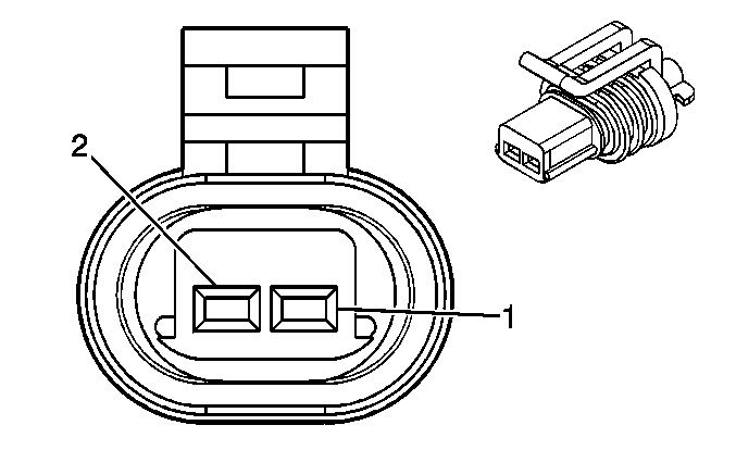
Connector Part Information |
| ||||||
Pin | Wire Color | Circuit No. | Function | ||||
1 | BU | 995 | Coolant Temperature Sensor Signal | ||||
2 | PK | G833 | Ground | ||||

| |||||||
|---|---|---|---|---|---|---|---|
Connector Part Information |
| ||||||
Pin | Wire Color | Circuit No. | Function | ||||
A | TN | 1997 | Ether Solenoid - Feed | ||||
B | BK | 350 | Battery Positive Voltage | ||||

| |||||||
|---|---|---|---|---|---|---|---|
Connector Part Information |
| ||||||
Pin | Wire Color | Circuit No. | Function | ||||
A | GY | A701 | Fuel Injector 1 Command | ||||
B | WH | L983 | Injector Supply Voltage | ||||

| |||||||
|---|---|---|---|---|---|---|---|
Connector Part Information |
| ||||||
Pin | Wire Color | Circuit No. | Function | ||||
A | PU | A702 | Fuel Injector 2 Command | ||||
B | WH | L983 | Injector Supply Voltage | ||||

| |||||||
|---|---|---|---|---|---|---|---|
Connector Part Information |
| ||||||
Pin | Wire Color | Circuit No. | Function | ||||
A | BN | A703 | Fuel Injector 3 Command | ||||
B | OG | L984 | Injector Supply Voltage | ||||

| |||||||
|---|---|---|---|---|---|---|---|
Connector Part Information |
| ||||||
Pin | Wire Color | Circuit No. | Function | ||||
A | GN | A704 | Fuel Injector 4 Command | ||||
B | OG | L984 | Injector Supply Voltage | ||||

| |||||||
|---|---|---|---|---|---|---|---|
Connector Part Information |
| ||||||
Pin | Wire Color | Circuit No. | Function | ||||
A | BU | A705 | Fuel Injector 5 Command | ||||
B | YE | L985 | Injector Supply Voltage | ||||

| |||||||
|---|---|---|---|---|---|---|---|
Connector Part Information |
| ||||||
Pin | Wire Color | Circuit No. | Function | ||||
A | GY | A706 | Fuel Injector 6 Command | ||||
B | YE | L985 | Injector Supply Voltage | ||||
| |||||||
|---|---|---|---|---|---|---|---|
Connector Part Information |
| ||||||
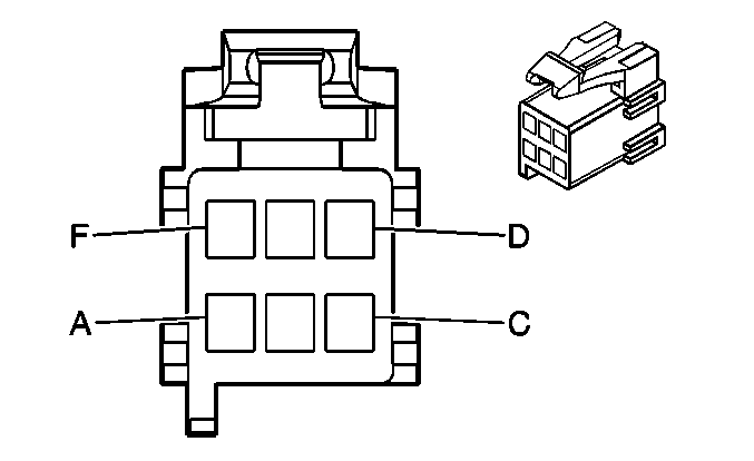
Pin | Wire Color | Circuit No. | Function | ||||
A | BK | 750 | Ground | ||||
B | BK | 750 | Ground | ||||
C | D-GN | 534 | High Idle Switch Signal | ||||
D | BN | 985 | IA Heater Relay Control | ||||
E | BN | 2509 | Left Rear Park Lamps Supply Voltage | ||||
F | BK | 750 | Ground | ||||
| |||||||
|---|---|---|---|---|---|---|---|
Connector Part Information |
| ||||||
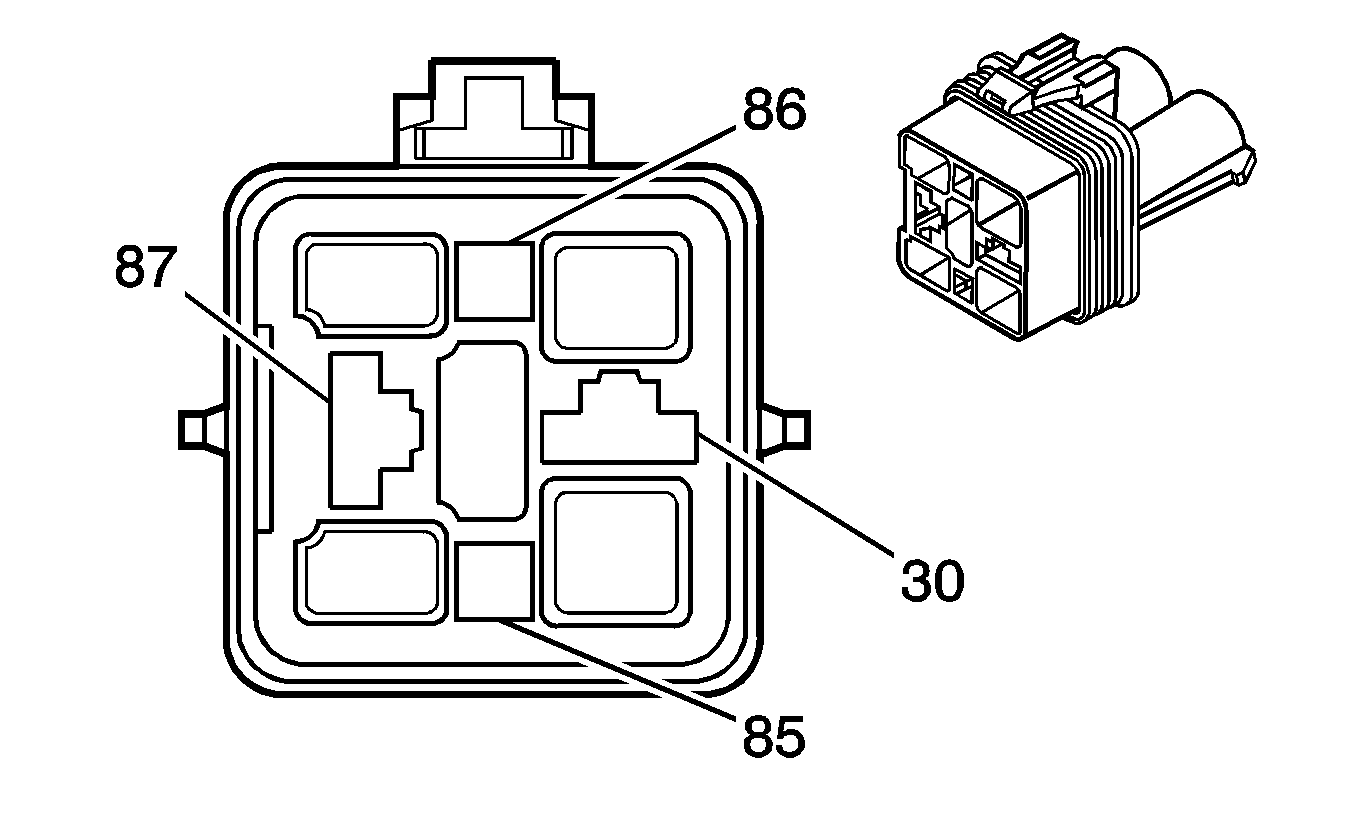
Pin | Wire Color | Circuit No. | Function | ||||
87 | RD | 2 | Battery Positive Voltage | ||||
85 | PK | 539 | Battery Positive Voltage | ||||
86 | BU | G850 | Ground | ||||
30 | RD | C967 | Intake Air Temperature Sensor Signal | ||||

| |||||||
|---|---|---|---|---|---|---|---|
Connector Part Information |
| ||||||
Pin | Wire Color | Circuit No. | Function | ||||
1 | BU | C967 | Intake Air Temperature Sensor Signal | ||||
2 | PK | G833 | Ground | ||||

| |||||||
|---|---|---|---|---|---|---|---|
Connector Part Information |
| ||||||
Pin | Wire Color | Circuit No. | Function | ||||
A | PK | G854 | Suction Control Valve Sensor Signal | ||||
B | PU | G855 | Low Reference | ||||

| |||||||
|---|---|---|---|---|---|---|---|
Connector Part Information |
| ||||||
Pin | Wire Color | Circuit No. | Function | ||||
1 | L-BU | 2221 | Signal High - Rear | ||||
2 | D-GN | 2222 | Signal Low - Rear | ||||

| |||||||
|---|---|---|---|---|---|---|---|
Connector Part Information |
| ||||||
Pin | Wire Color | Circuit No. | Function | ||||
A | YE/BK | 508 | Water In Fuel Indicator Control | ||||
B | BK/WH | 351 | Ground | ||||
