Intake Manifold Replacement w/o CTF
Removal Procedure
- Disconnect the negative battery cable.
- Remove the air cleaner layer. Refer to Air Cleaner Replacement in Engine Controls.
- Remove the engine cover. Refer to Engine Cover Replacement in Interior Trim.
- Remove the air charge tube from the intake manifold. Refer to Charge Air Cooler Replacement in Engine Controls - 7.8L.
- Remove the air intake heater. Refer to Intake Air Heater Replacement in Engine Controls - 7.8L.
- Remove the engine oil indicator tube.
- Remove the heater hose retainer and position the heater hose out of the way.
- Disconnect the engine harness retainers and reposition the engine harness out of the way.
- Remove the crankcase breather tube fasteners and reposition the tube out of the way.
- Disconnect the MAT and boost sensor electrical connectors.
- Disconnect the fuel pressure sensor connector.
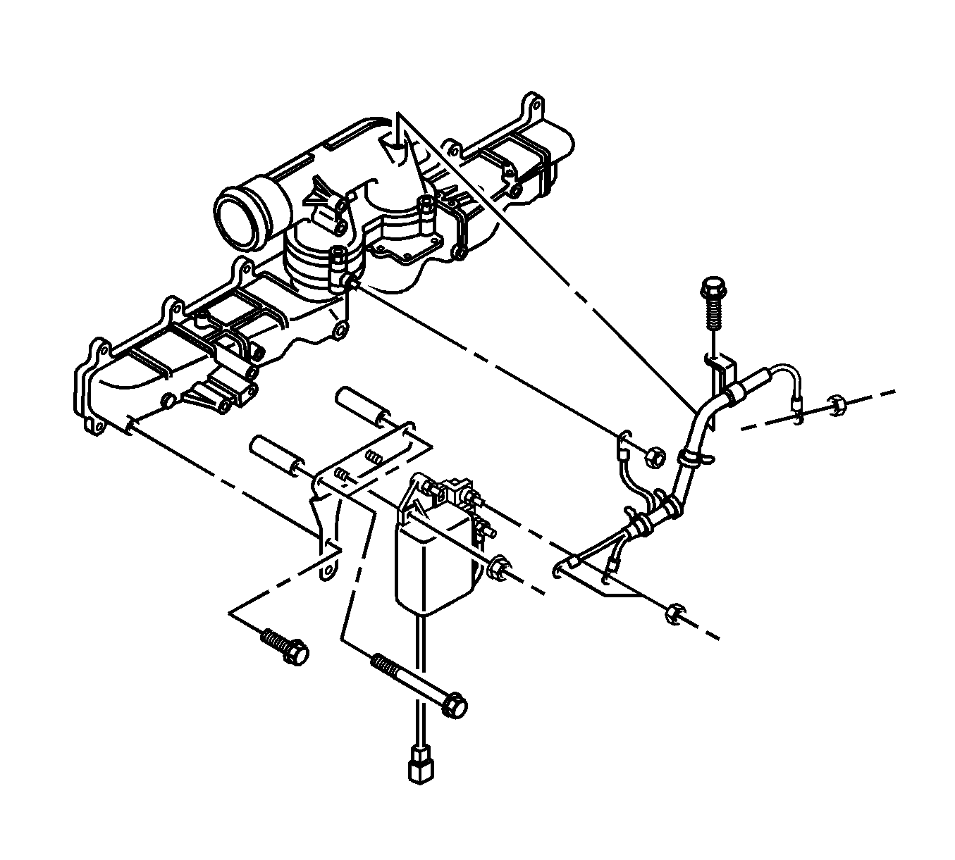
- Disconnect the air intake heater harness from the intake manifold.
- Remove the 3 bolts and the air intake pipe from the manifold.
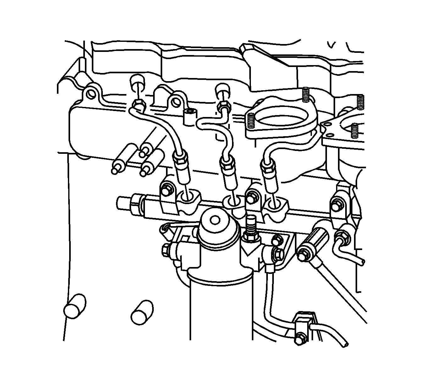
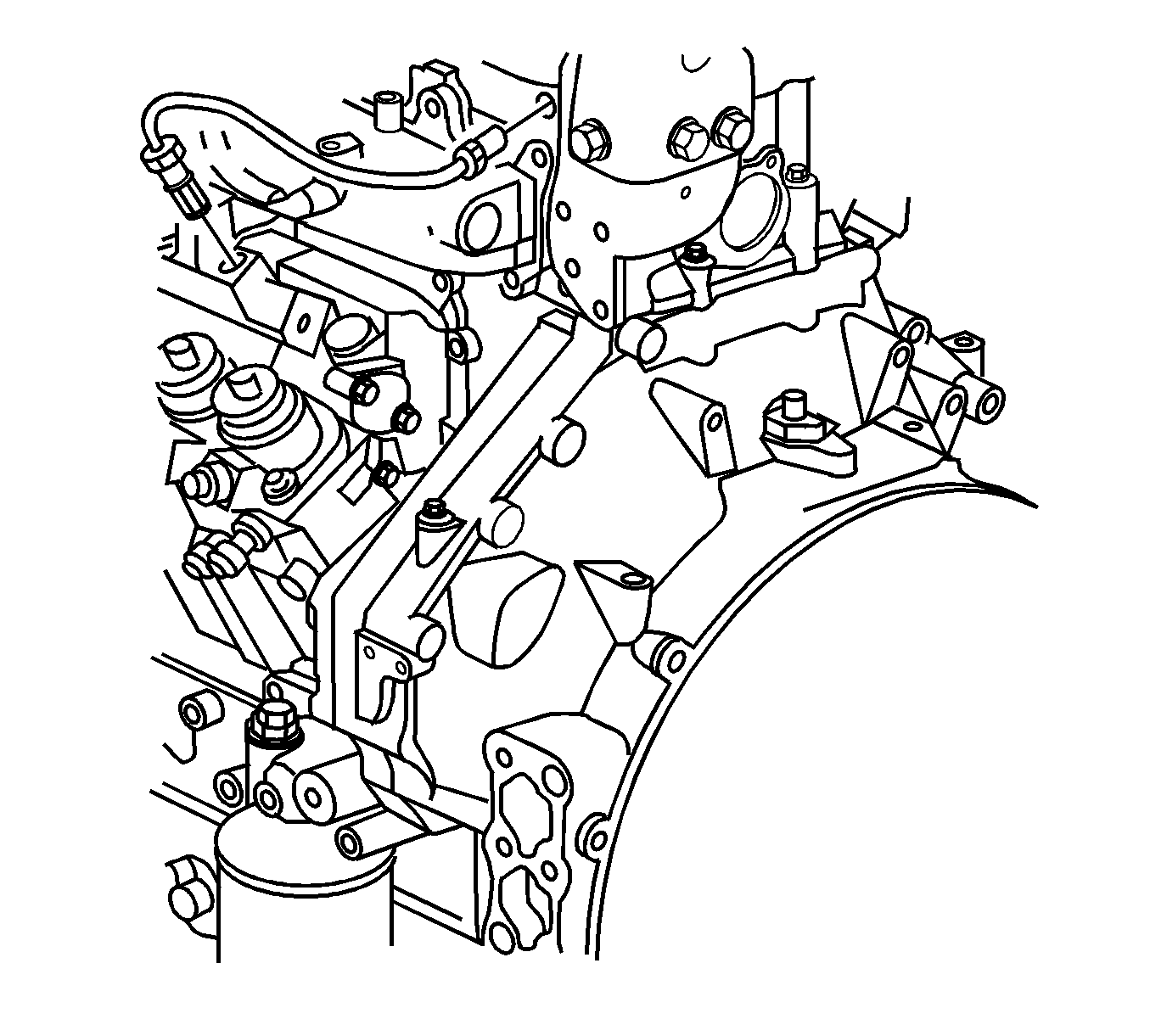
- Remove the fuel lines from the common rail to the fuel injector.
- Remove the fuel lines from the supply pump to the common rail.
- Remove the fuel injector return line from the fuel injector, fuel common rail and the fuel supply pump.
- Remove the fuel filter and bracket from the intake manifold. Refer to Fuel Filter Replacement in Engine Controls - 7.8L.
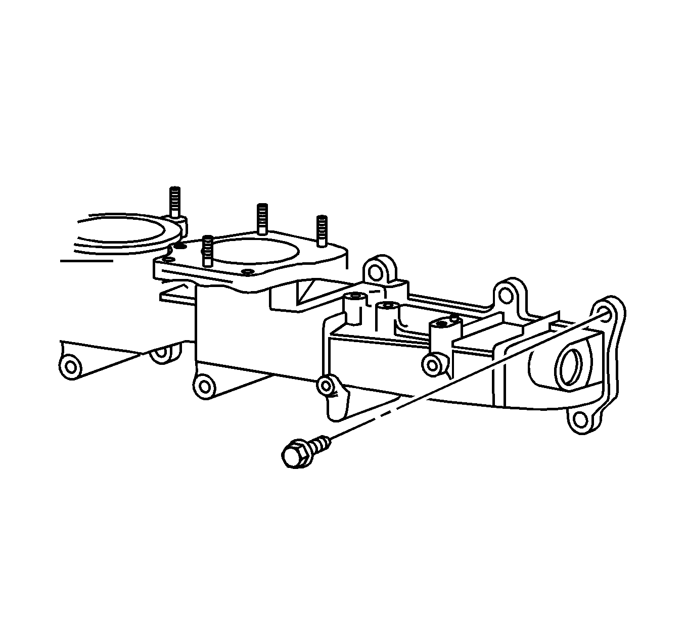
- Remove the intake manifold bolts.
- While removing the intake manifold and gasket, disconnect the air compressor air line at the rear of the manifold, if equipped.
Caution: Unless directed otherwise, the ignition and start switch must be in the OFF or LOCK position, and all electrical loads must be OFF before servicing any electrical component. Disconnect the negative battery cable to prevent an electrical spark should a tool or equipment come in contact with an exposed electrical terminal. Failure to follow these precautions may result in personal injury and/or damage to the vehicle or its components.
Important: Do not bend the fuel injector lines in any shape or form to ease the removal of the intake manifold.
Installation Procedure
- Install the intake manifold and gasket while connecting the air compressor air line at the rear of the manifold.
- Install the intake manifold bolts.
- Install the common fuel rail.
- Install the fuel lines from the supply pump to the common rail.
- Install the fuel lines from the common rail to the fuel injector.
- Install the fuel injector return line from the fuel injector, fuel common rail and the fuel supply pump.
- Install the fuel filter and the bracket to the intake manifold. Refer to Fuel Filter Replacement in Engine Controls - 7.8L.
- Install the air intake heater. Refer to Intake Air Heater Replacement in Engine Controls - 7.8L.
- Install the air charge tube to the intake manifold. Refer to Charge Air Cooler Replacement in Engine Controls - 7.8L.
- Install the air intake heater relay to the manifold, if equipped.
- Connect the electrical connector to the air intake heater relay.
- Reposition the engine harness and connect the MAT, boost, and fuel pressure sensors.
- Reposition the oil fill tube and install the fastener.
- Connect the negative battery cable.
- Install the Engine Cover. Refer to Engine Cover Replacement in Interior Trim.
- Install the air cleaner layer. Refer to Air Cleaner Replacement in Engine Controls - 7.8L.
Important: Inspect the intake manifold for cracks or damage to the gasket mating surface.
Notice: Refer to Fastener Notice in the Preface section.
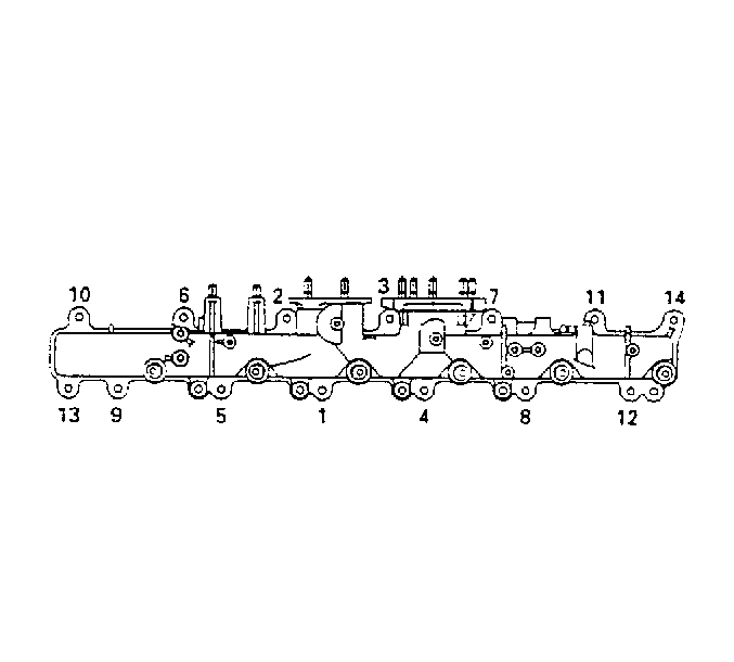
Tighten
Tighten the intake manifold bolts to 15 N·m (11 lb ft).


Intake Manifold Replacement w/CTF
Removal Procedure
- Remove the engine cover. Refer to Engine Cover Replacement .
- Remove the charge air cooler pipe from the intake pipe. Refer to Charge Air Cooler Inlet Pipe and Outlet Pipe Replacement .
- Disconnect the negative battery cable. Refer to Battery Negative Cable Disconnection and Connection .
- Disconnect the manifold absolute pressure (MAP) sensor electrical connector.
- Disconnect the air temperature sensor connector.
- Remove the power steering line clamp fasteners at the intake manifold and the valve cover.
- Remove the fuel filter and bracket from the intake manifold. Refer to Fuel Filter Replacement .
- Remove the exhaust gas recirculation (EGR) valve. Refer Exhaust Gas Recirculation Valve Replacement .
- Remove the fuel lines from the common rail to the fuel injector.
- Remove the fuel lines from the supply pump to the common rail.
- Remove the fuel injector return line from the fuel injector, fuel common rail and the fuel supply pump.
- Remove the intake manifold bolts.
- Remove the intake manifold and gasket.

Important: Do not bend the fuel injector lines in any shape or form to ease the removal of the intake manifold.

Installation Procedure
- Install the intake manifold and gasket.
- Install the intake manifold bolts.
- Install the common fuel rail.
- Install the fuel lines from the supply pump to the common rail.
- Install the fuel lines from the common rail to the fuel injector.
- Install the fuel injector return line from the fuel injector, fuel common rail and the fuel supply pump.
- Install the fuel filter and the bracket to the intake manifold. Refer to Fuel Filter Replacement .
- Connect the MAP sensor.
- Connect the air temperature sensor.
- Install the EGR valve . Refer Exhaust Gas Recirculation Valve Replacement .
- Connect the negative battery cable. Refer to Battery Negative Cable Disconnection and Connection .
- Install the charge air cooler pipe. Refer to Charge Air Cooler Inlet Pipe and Outlet Pipe Replacement .
- Install the engine cover. Refer to Engine Cover Replacement .

Important: Inspect the intake manifold for cracks or damage to the gasket mating surface.
Notice: Refer to Fastener Notice in the Preface section.

Tighten
Tighten the intake manifold bolts to 15 N·m (11 lb ft).
