GM Service Manual Online
For 1990-2009 cars only
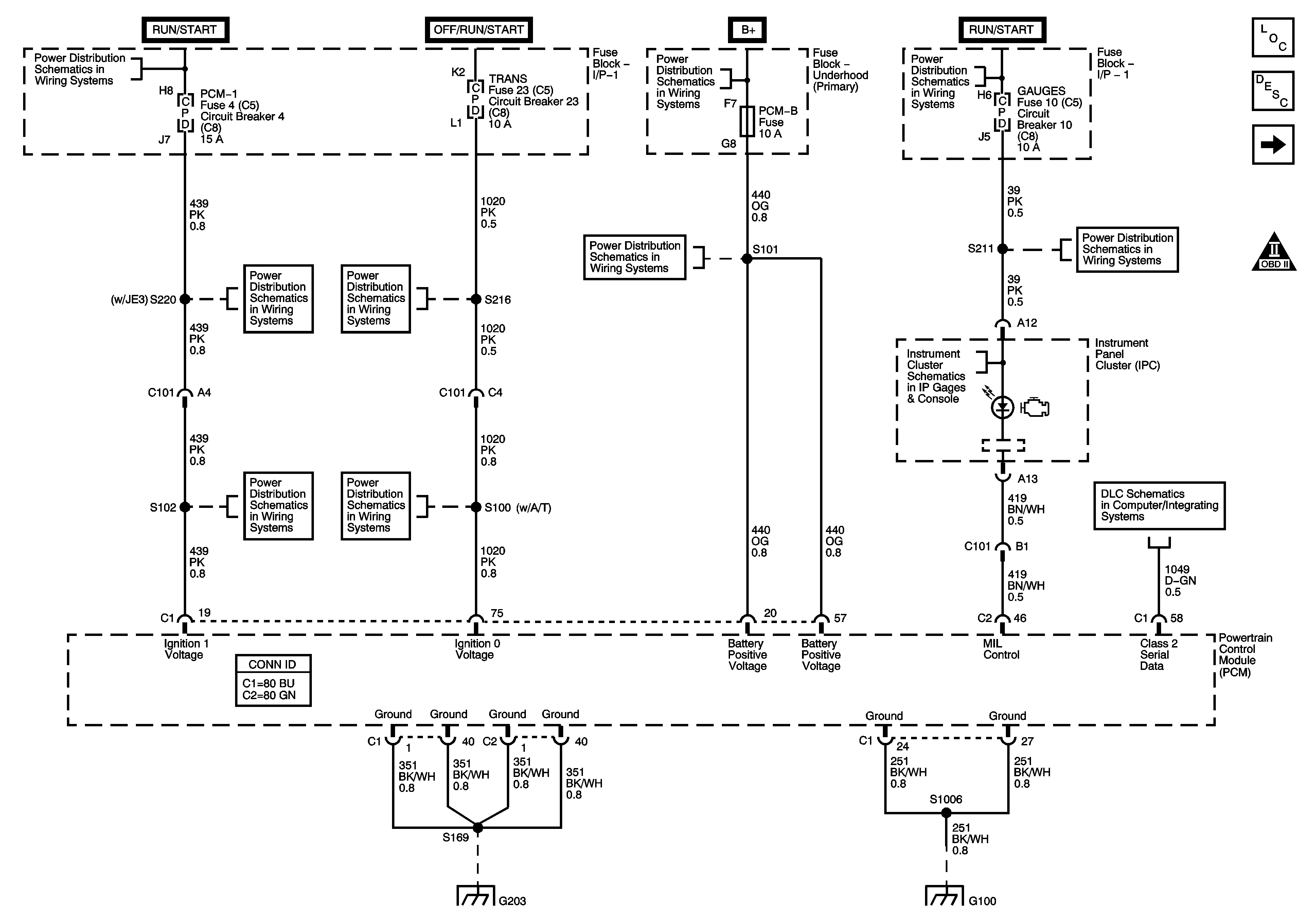
Figure 1:

Module Power, Ground, Serial Data, and MIL

Object Number: 1825127  Size: FS
Master Electrical Component List
Powertrain Control Module Description
Engine Data Sensors - 5-Volt and Low Reference
Engine Controls Schematic Icons
Ignition Switch - OFF/RUN/START, RUN/START, and START Bus Bars
ENGINE and PCM-1 Fuses/Circuit Breakers
TRANS Fuse/Circuit Breaker
A/C COMP, HTD FUEL, PCM-B, and RR DEFOG Fuses
Batteries - LG4/LG5 and B+ Bus
Ignition Switch - OFF/RUN/START, RUN/START, and START Bus Bars
AIRBAG, GAUGES, LT REAR TURN/STOP, and RT REAR TURN/STOP Fuses/Circuit Breakers
Instrument Panel Cluster - 1 of 2
Splice Pack SP203
G203 - 2 of 4
G100 - L18
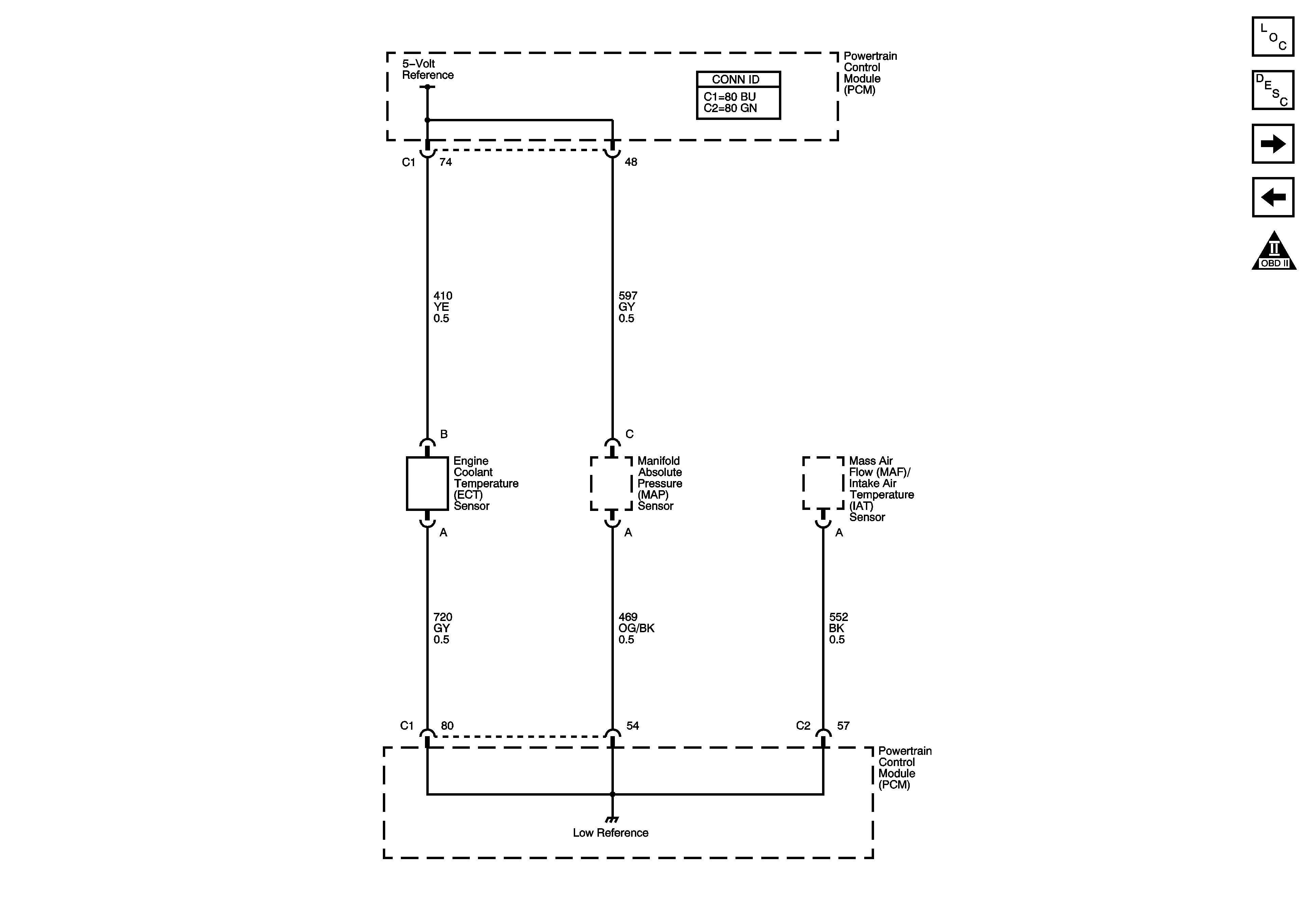
Figure 2:

Engine Data Sensors - 5-Volt and Low Reference


Object Number: 1825130  Size: FS
Master Electrical Component List
Powertrain Control Module Description
Fuse Block - Underhood and IGN-A Relay
Module Power, Ground, Serial Data, and MIL
Engine Controls Schematic Icons
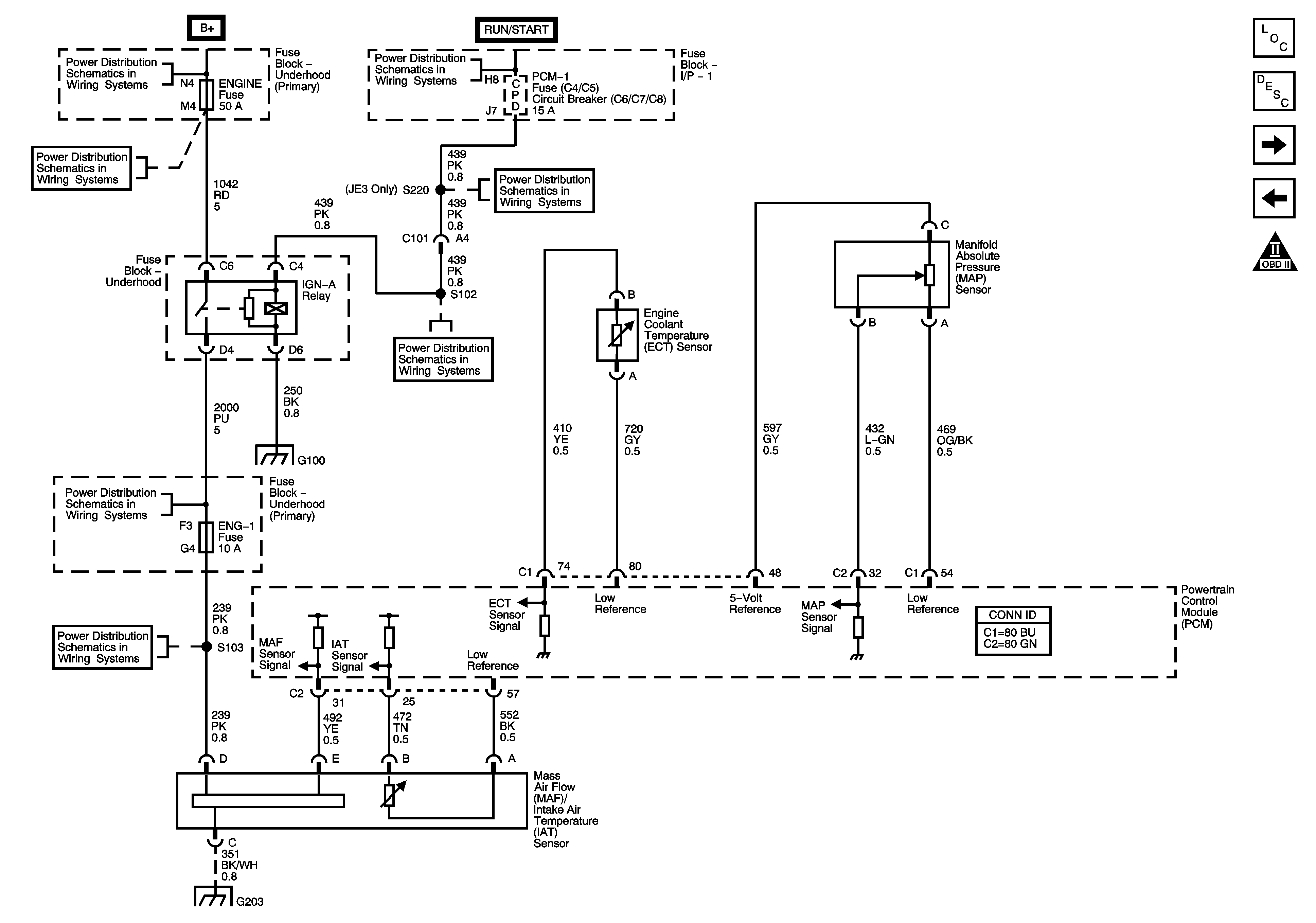
Figure 3:

Fuse Block - Underhood and IGN-A Relay


Object Number: 1825133  Size: FS
Master Electrical Component List
Powertrain Control Module Description
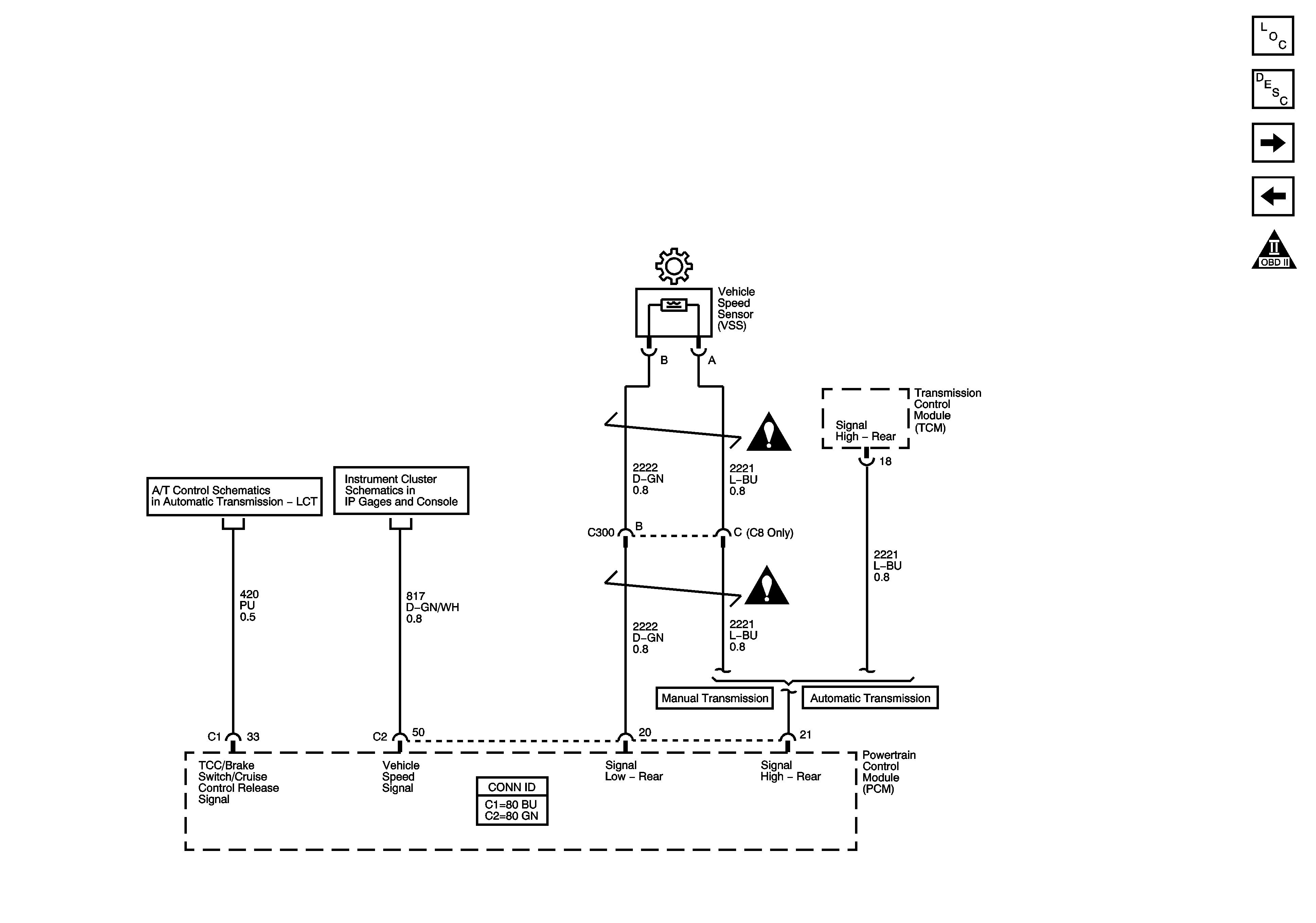
Engine Data Sensors - VSS
Engine Data Sensors - 5-Volt and Low Reference
Engine Controls Schematic Icons
Batteries - LG4/LG5 and B+ Bus
Ignition Switch - OFF/RUN/START, RUN/START, and START Bus Bars
ENGINE and PCM-1 Fuses/Circuit Breakers
G100 - L18
ENG-1 and ENG-4 Fuses - L18/LLY
G203 - 2 of 4
Figure 4:

Engine Data Sensors - VSS


Object Number: 1825135  Size: FS
Master Electrical Component List
Powertrain Control Module Description
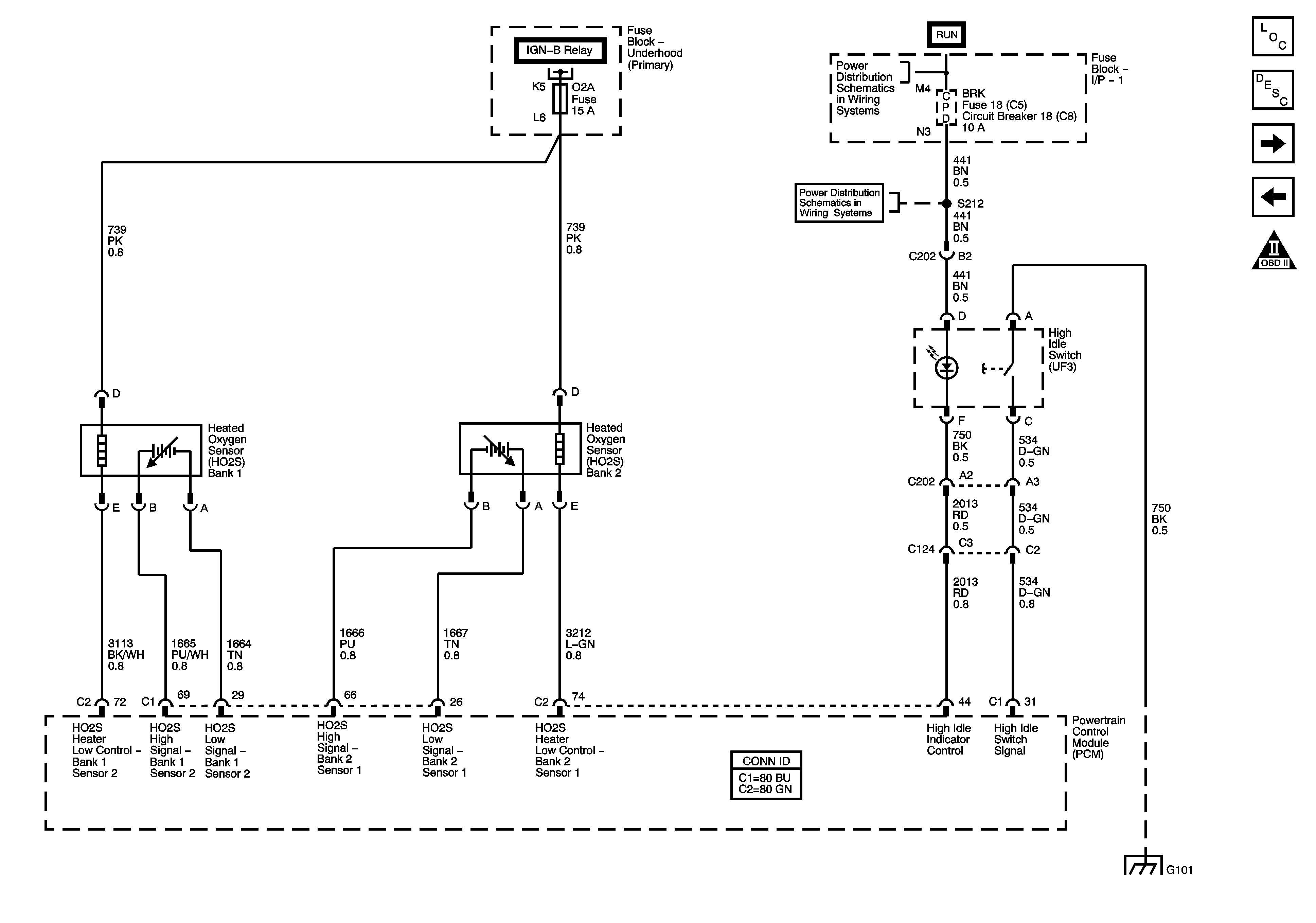
Engine Data Sensors - HO2S
Fuse Block - Underhood and IGN-A Relay
Engine Controls Schematic Icons
LG4 and LLY
Instrument Panel Cluster - 2 of 2
Engine Controls Schematic Icons
Figure 5:

Engine Data Sensors - HO2S


Object Number: 1825138  Size: FS
Master Electrical Component List
Powertrain Control Module Description
Engine Data Sensors - Electronic Throttle Controls
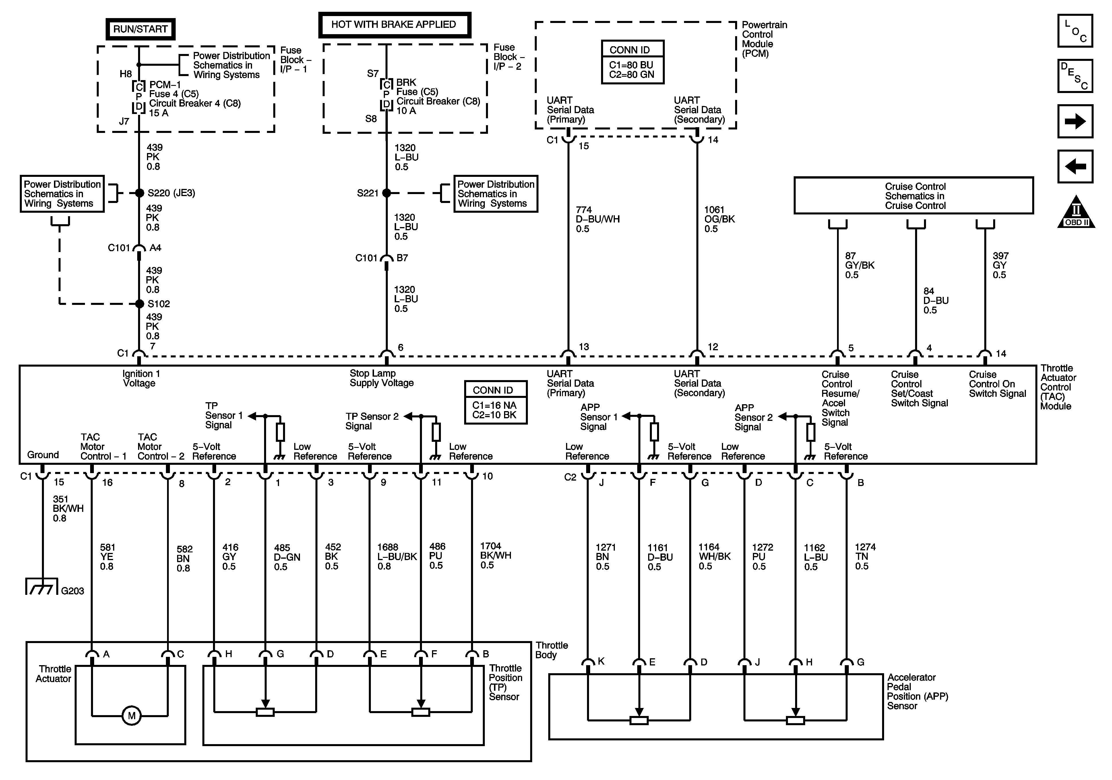
Engine Data Sensors - VSS
Engine Controls Schematic Icons
Ignition Controls - Ignition Systems - 1 of 2
AXL/4WD, BRK, HTR/AC, and HYD/AIR BRK Fuses/Circuit Breakers
Ignition Switch - RUN and ACC/RUN Bus Bars and IGN 3 Fuse
G101 - 1 of 2
Figure 6:

Engine Data Sensors - Electronic Throttle Controls


Object Number: 1825142  Size: FS
Master Electrical Component List
Throttle Actuator Control (TAC) System Description
Ignition Controls - Ignition Systems - 1 of 2
Engine Data Sensors - HO2S
Engine Controls Schematic Icons
ENGINE and PCM-1 Fuses/Circuit Breakers
Ignition Switch - OFF/RUN/START, RUN/START, and START Bus Bars
BRK Fuse/Circuit Breaker
LG4 and LLY
G203 - 2 of 4
Figure 7:

Ignition Controls - Ignition Systems 1 of 2
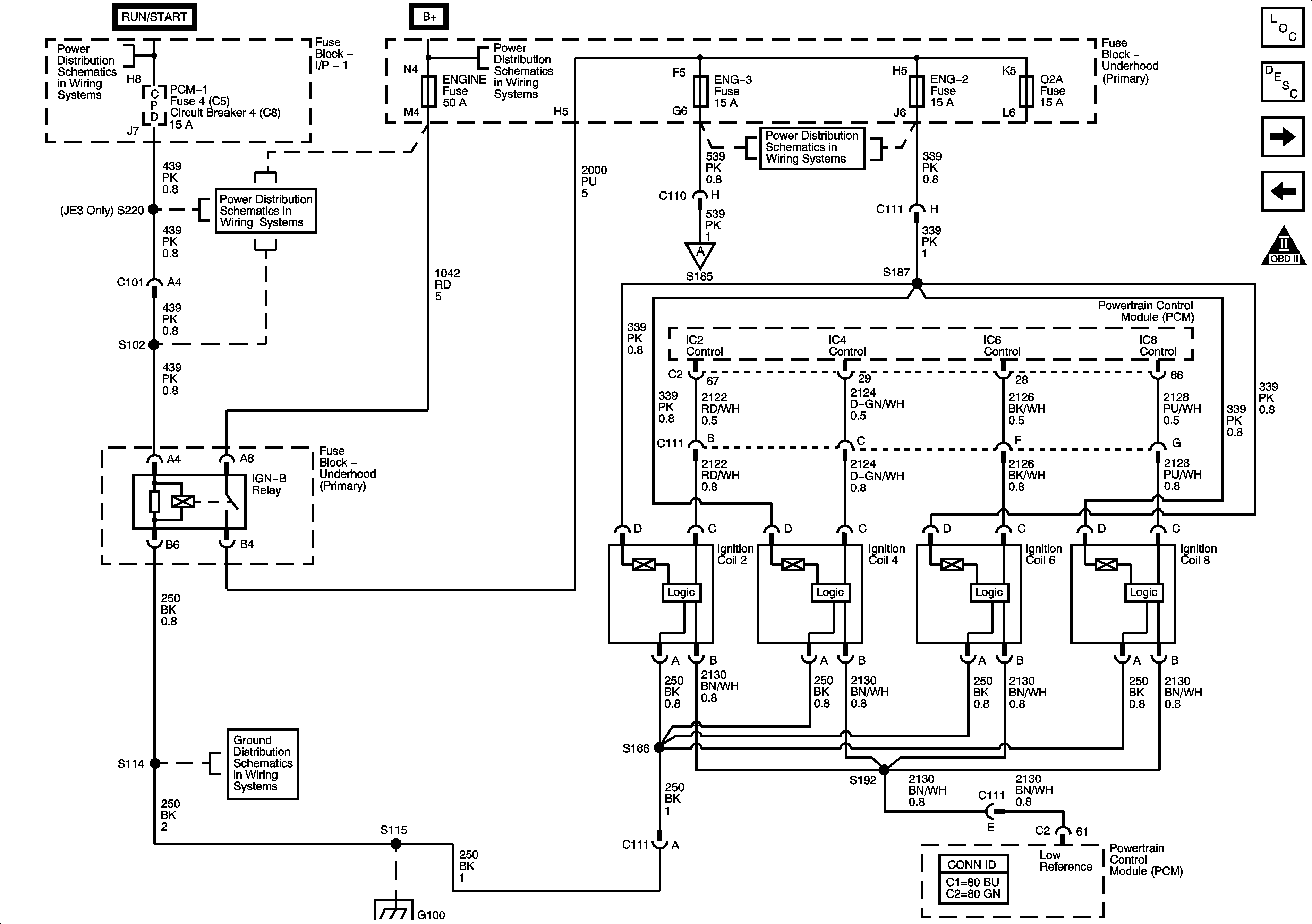

Object Number: 1825144  Size: FS
Master Electrical Component List
Electronic Ignition (EI) System Description
Ignition Controls - Ignition Systems - 2 of 2
Engine Data Sensors - Electronic Throttle Controls
Engine Controls Schematic Icons
Ignition Switch - OFF/RUN/START, RUN/START, and START Bus Bars
ENGINE and PCM-1 Fuses/Circuit Breakers
Batteries - LG4/LG5 and B+ Bus
Ignition Controls - Ignition Systems - 2 of 2
ENG-2, ENG-3, and O2S Fuses - L18
G100 - L18
G100 - L18
Figure 8:

Ignition Controls - Ignition Systems 2 of 2
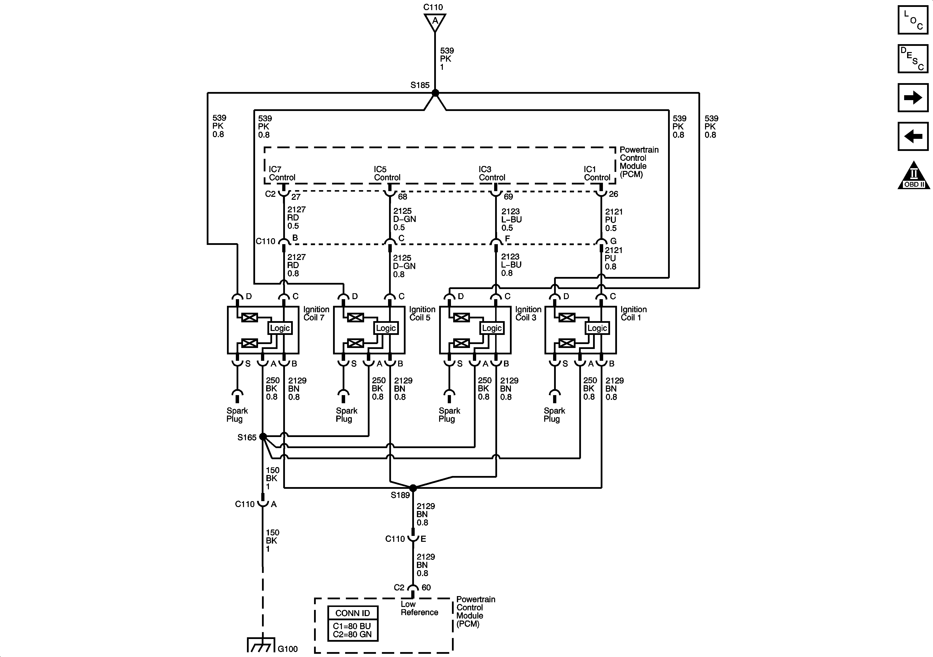

Object Number: 1825145  Size: FS
Master Electrical Component List
Electronic Ignition (EI) System Description
Ignition System - CKP, CMP, and KS Sensors
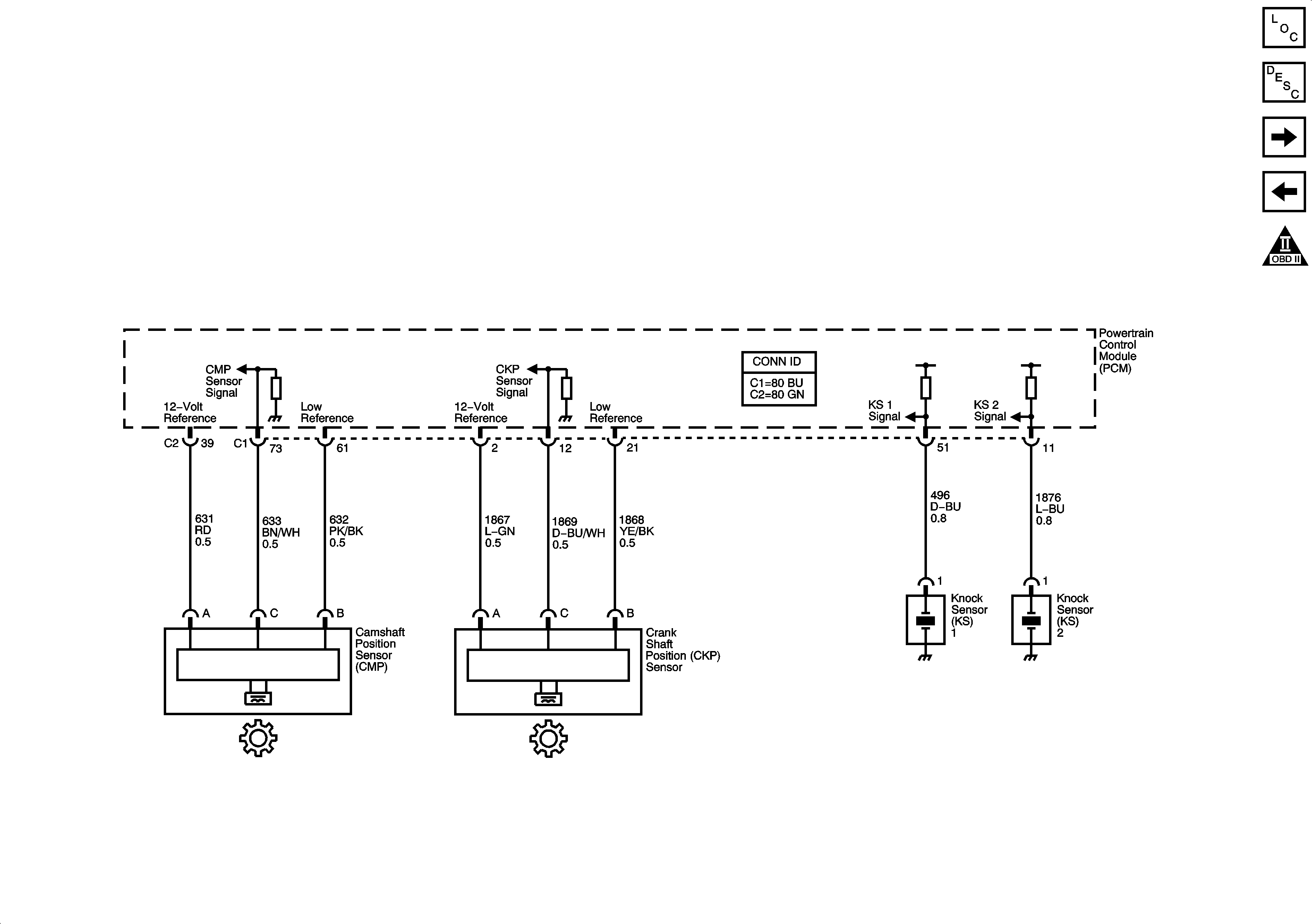
Ignition Controls - Ignition Systems - 1 of 2
Engine Controls Schematic Icons
Ignition Controls - Ignition Systems - 1 of 2
G100 - L18
Figure 9:

Ignition System - CKP, CMP, and KS Sensors


Object Number: 1825146  Size: FS
Master Electrical Component List
Electronic Ignition (EI) System Description
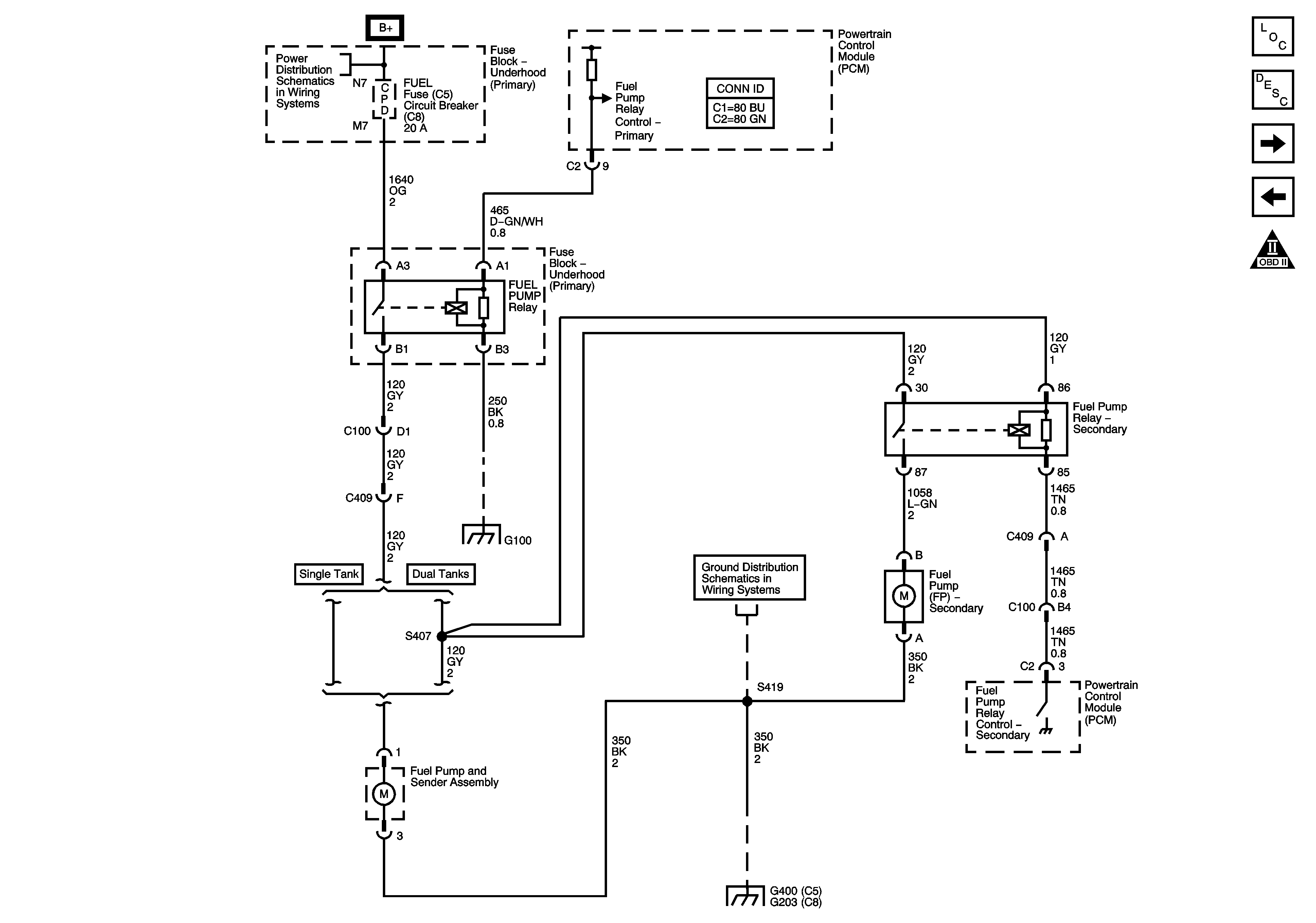
Fuel Controls - Fuel Pump Controls
Ignition Controls - Ignition Systems - 2 of 2
Engine Controls Schematic Icons
Figure 10:

Fuel Controls - Fuel Pump Controls


Object Number: 1825147  Size: FS
Master Electrical Component List
Fuel System Description
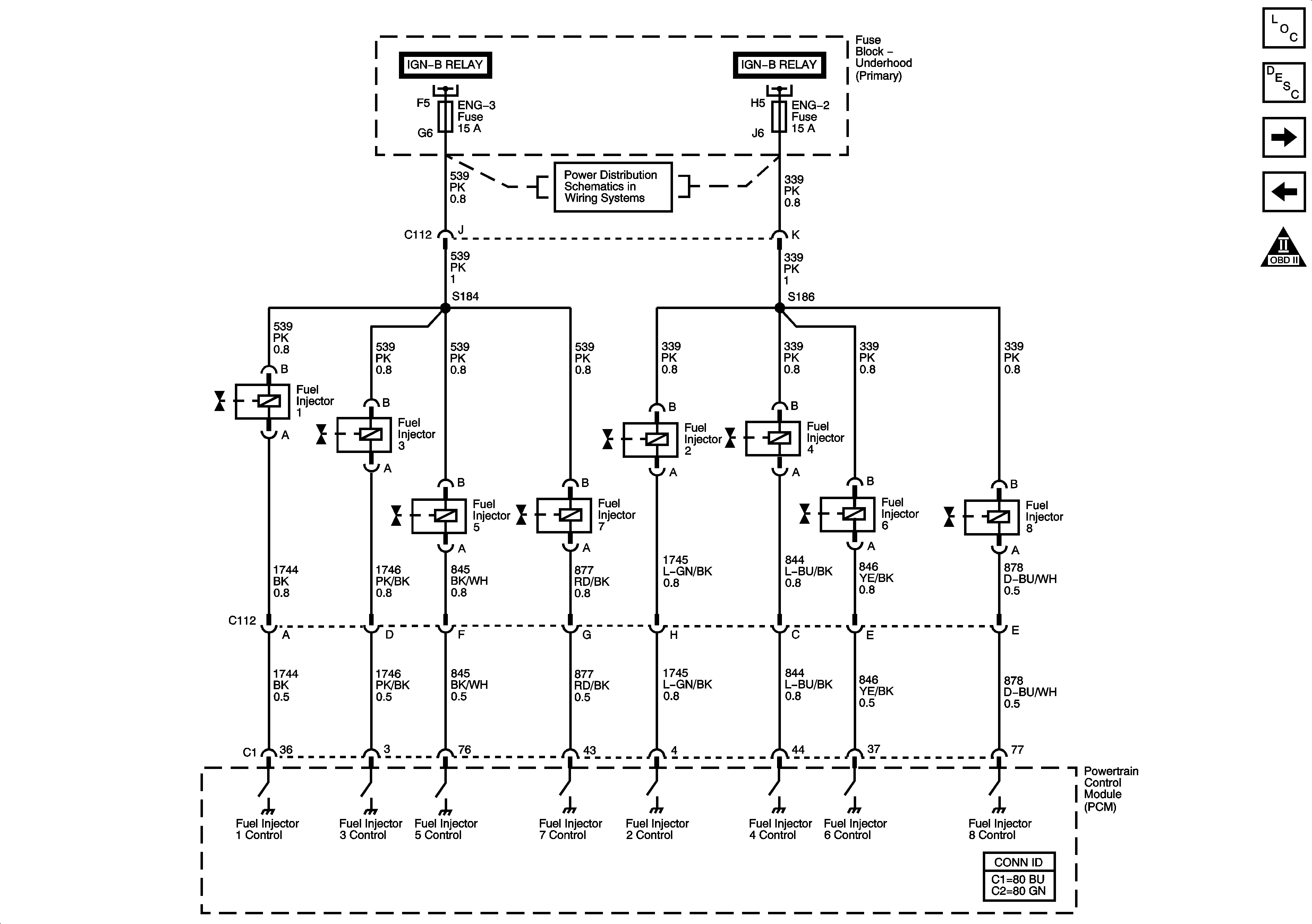
Fuel Controls - Fuel Injectors
Ignition System - CKP, CMP, and KS Sensors
Engine Controls Schematic Icons
Batteries - LG4/LG5 and B+ Bus
G100 - L18
G112, G113, G203 - 4 of 4, G204, G205, and G400
Figure 11:

Fuel Controls - Fuel Injectors


Object Number: 1825148  Size: FS
Master Electrical Component List
Fuel System Description
Device Controls - EGR Valve
Fuel Controls - Fuel Pump Controls
Engine Controls Schematic Icons
Ignition Controls - Ignition Systems - 1 of 2
ENG-2, ENG-3, and O2S Fuses - L18
Figure 12:

Device Controls - EGR Valve


Object Number: 1825149  Size: FS
Master Electrical Component List
Evaporative Emission Control System Description
Controlled/Monitored Subsystem References
Fuel Controls - Fuel Injectors
Engine Controls Schematic Icons
ENG-1 and ENG-4 Fuses - L18/LLY
Instrument Panel Cluster - 2 of 2
A/C Compressor Controls - L18/LLY
Starting System (L18/LLY)
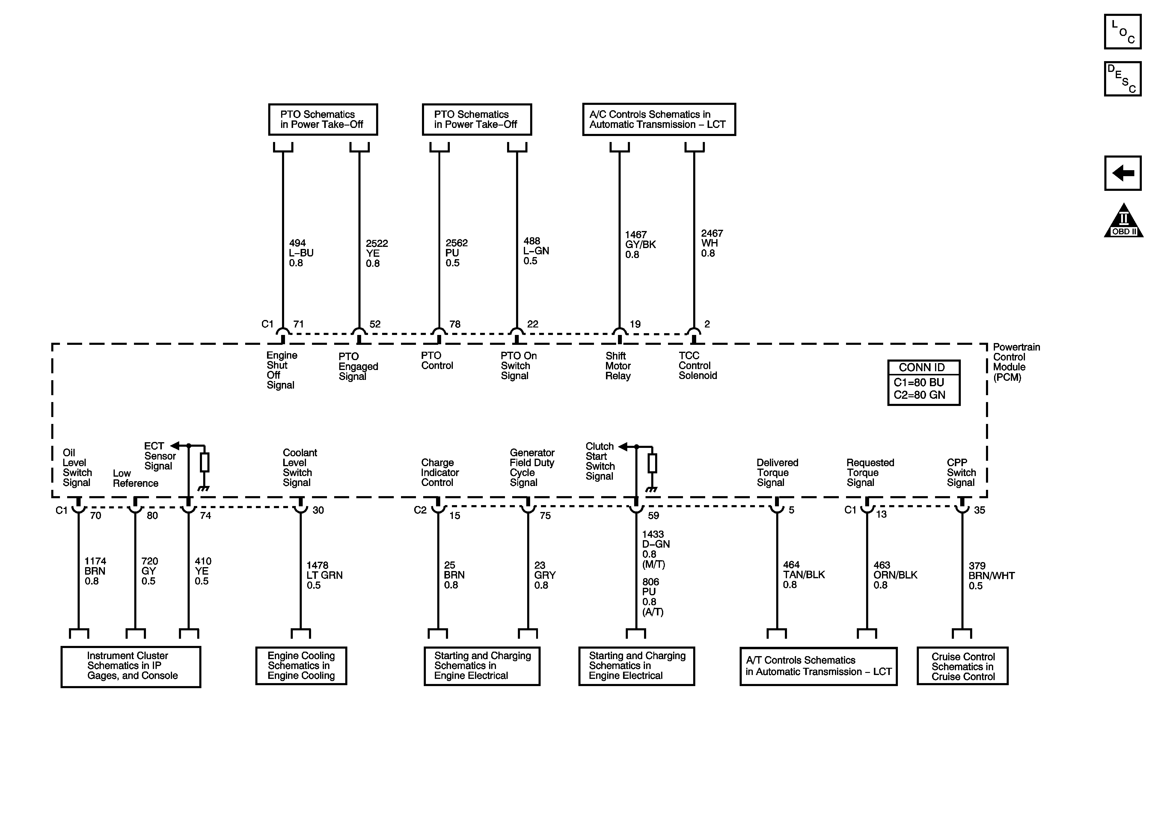
Figure 13:

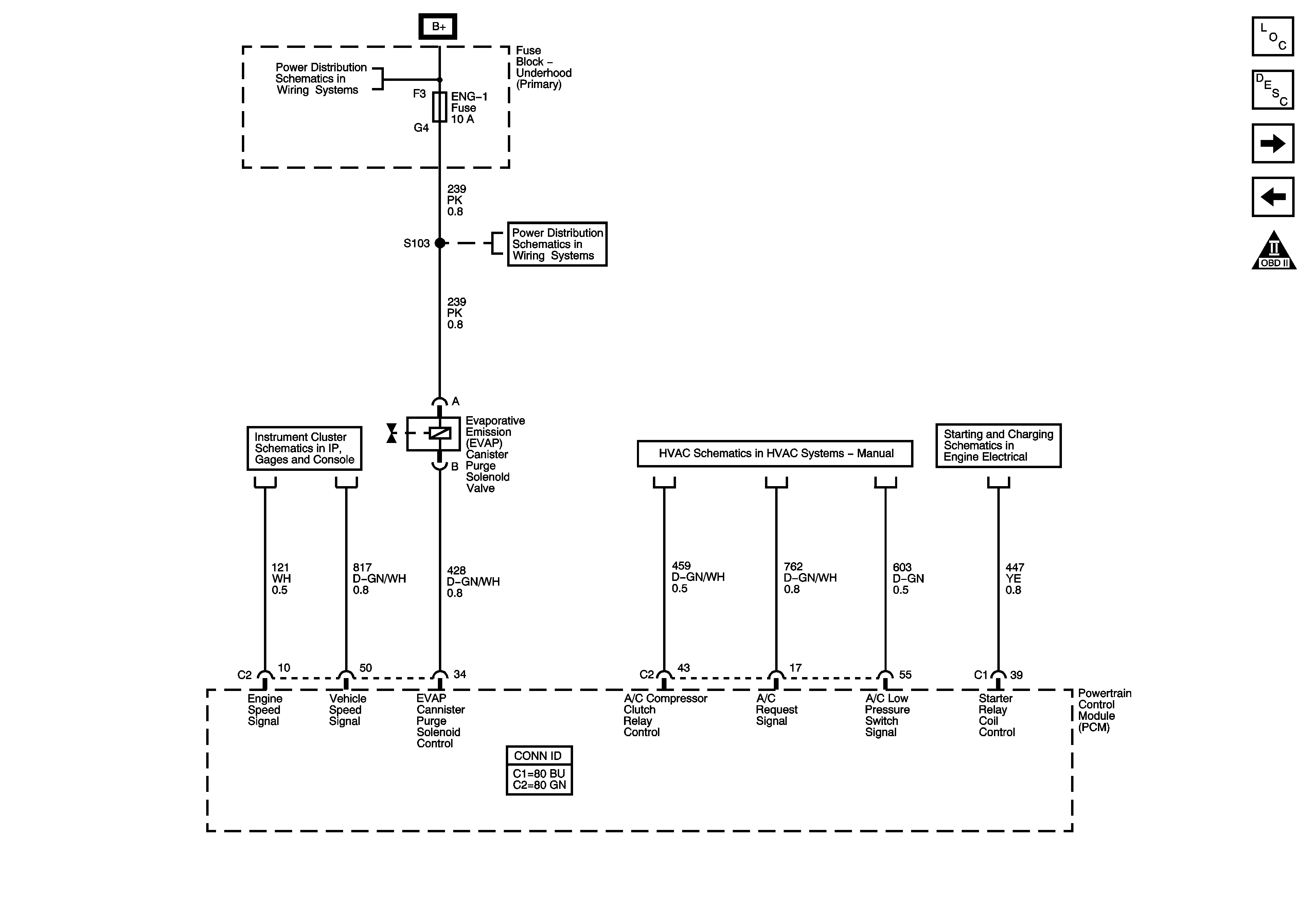
Controlled/Monitored Subsystem References


Object Number: 1825151  Size: FS
Master Electrical Component List
Powertrain Control Module Description
Device Controls - EGR Valve
Engine Controls Schematic Icons
2 of 2
1 of 2
Module Power, Ground, Serial Data, MIL, VSS, and Torque Controls - L18/LLY
Instrument Panel Cluster - 2 of 2
Engine Cooling Schematics
Charging System (L18/LLY)
Starting System (L18/LLY)
Module Power, Ground, Serial Data, MIL, VSS, and Torque Controls - L18/LLY
LG4 and LLY