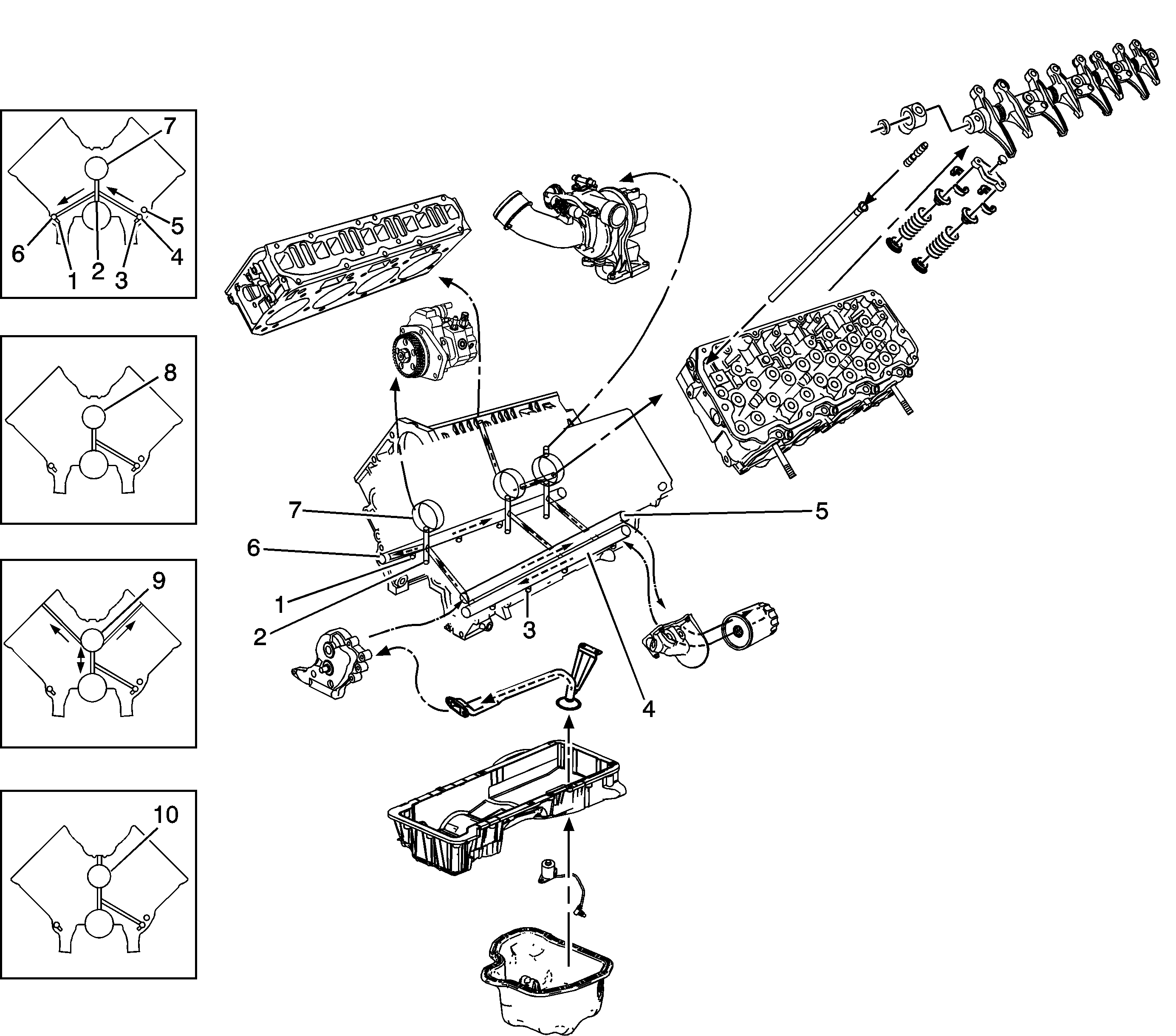
Lubrication Flow Schematic

Engine lubrication is supplied by a gear type oil pump assembly. The pump is mounted on the front of the engine block and driven by the oil pump drive gear on the crankshaft. The pump gears rotate and draw oil from the oil pan sump through a pick-up screen and pipe. The oil is pressurized as it passes through the pump and is sent through the engine block oil galleries. Contained within the oil pump assembly is a safety relief valve that eliminates overpressurization. Pressurized oil is directed through the sub oil gallery (5) to the full flow oil filter where harmful contaminants are removed. Two bypass valves are incorporated into the oil cooler assembly which will permit oil flow in the event the filter or the oil cooler become restricted.
The oil is directed to the main oil gallery (4), and from the main oil gallery it flows to the piston cooling channel left bank (3), and the sub oil gallery (6) on the right bank. The sub oil gallery on the right bank supplies oil to the right bank piston cooling channel (1). Located in the front cover at the sub oil gallery (6) is an oil pressure relief valve which regulates oil pressure within operating range.
Oil flows from the main gallery (4) to the vertical crankshaft/camshaft bearing galleries (2). From the crankshaft/camshaft bearing galleries (2), the oil flows to both the camshaft bearings and the crankshaft main bearings. Oil flows from the crankshaft main bearings to the connecting rod big end.
Oil flows from the crankshaft/camshaft bearing galleries (2) to the number 1 camshaft bearing (7), where it splash lubricates the fuel injection pump gear.
Oil flows from the crankshaft/camshaft bearing galleries (2) to the number 2 and 5 camshaft bearings (8).
Oil flows from the crankshaft/camshaft bearing galleries (2) to the number 3 camshaft bearing (9), where it exits to both cylinder heads and enters the hollow rocker arm shafts. Oil flows through the rocker arm shafts and rocker arms where it lubricates the upper valve train components.
On production LB7 engines through 2004, oil flowed through the rocker arms, through the passage in the valve adjusting screw, and into the hollow pushrods where it was directed to the valve lifters. Beginning with the 2004.5 engine (LLY), lifters with hardened rollers were used and did not require hollow pushrods for additional oil flow. However, hollow pushrods were used in production until approximately the start of the 2006 model year, after which the hole in the push rod ends was removed. The hollow pushrods can be used for any model year, whereas the pushrods without the holes in the ends can only be used for 2004.5 model year and newer production engines.
Oil flows from the crankshaft/camshaft bearing galleries (2) to the number 4 camshaft (10), where it exits into the turbocharger oil supply line to lubricate the turbocharger. Oil exiting the turbocharger is routed through the turbocharger oil return pipe and into the flywheel housing.
