Front Case Half
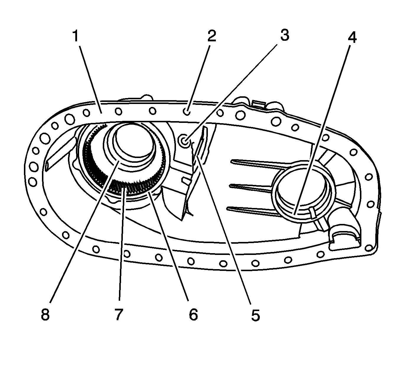
- Clean the front case half in cleaning solvent and air dry.
Notice: Refer to Machined Surface Damage Notice in the Preface section.
- Remove the sealer from the case sealing surface (1).
- Inspect the case for being broken or cracked.
- Inspect the front output shaft front bearing bore (4) for the following conditions:
- Inspect the input shaft bearing bore (8) for the following conditions:
- Replace the front case half if any of the above is found.
- Inspect the sealing surface (1) for damage.
- Repair small scratches or nicks with a soft stone.
- Inspect the front case to bracket mounting surface for damage.
- Inspect the case threaded bolt holes (2) for damage.
- Repair any damaged threads.
- Inspect the location pins for being loose or missing.
- Repair or replace any damaged location pins.
- Inspect the retaining ring (6) of the annulus gear to ensure it is properly seated.
- Inspect the annulus gear (7) for the following conditions:
| • | Debris embedded in the root of the teeth |
- Replace the front case half if the annulus gear is damaged.
- Inspect the shift shaft hole (3) for excessive wear.
- Replace the front case half if the shift shaft hole (3) is worn.
- Inspect the sector bearing and seal (5) for the following conditions:
- Replace the sector bearing if it is faulty. Refer to
Transfer Case Disassemble
and
Transfer Case Assemble
.
- Inspect the front output shaft front bearing and the input shaft bearing for the following conditions:
- Replace the bearings if any of the above conditions are found. Refer to
Transfer Case Disassemble
and
Transfer Case Assemble
.
Rear Case Half
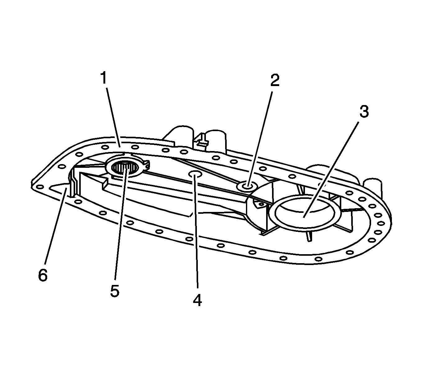
- Clean the rear case half in cleaning solvent and air dry.
Notice: Refer to Machined Surface Damage Notice in the Preface section.
- Remove the sealer from the case sealing surfaces.
- Inspect the case for being broken or cracked.
- Replace the case if it is broken or cracked.
- Inspect the sealing surfaces for damage.
- Repair small scratches or nicks with a soft stone.
- Inspect the shift shaft hole (2) for excessive wear.
- Replace the case if the shift shaft hole (2) is worn.
- Inspect the case threaded bolt holes for damage.
- Repair any damaged threads.
- Inspect the front output needle bearing (5) for the following conditions:
- Replace the front output needle bearing if any of the above conditions are found. Refer to
Transfer Case Disassemble
and
Transfer Case Assemble
.
- Inspect the rear output bearing for the following conditions:
- Replace the rear output bearing if any of the above conditions are found. Refer to
Transfer Case Disassemble
and
Transfer Case Assemble
.
- Inspect for a spun bearing bore (3) for the rear output bearing.
- Replace the case if a bearing has spun.
Retainer Assembly
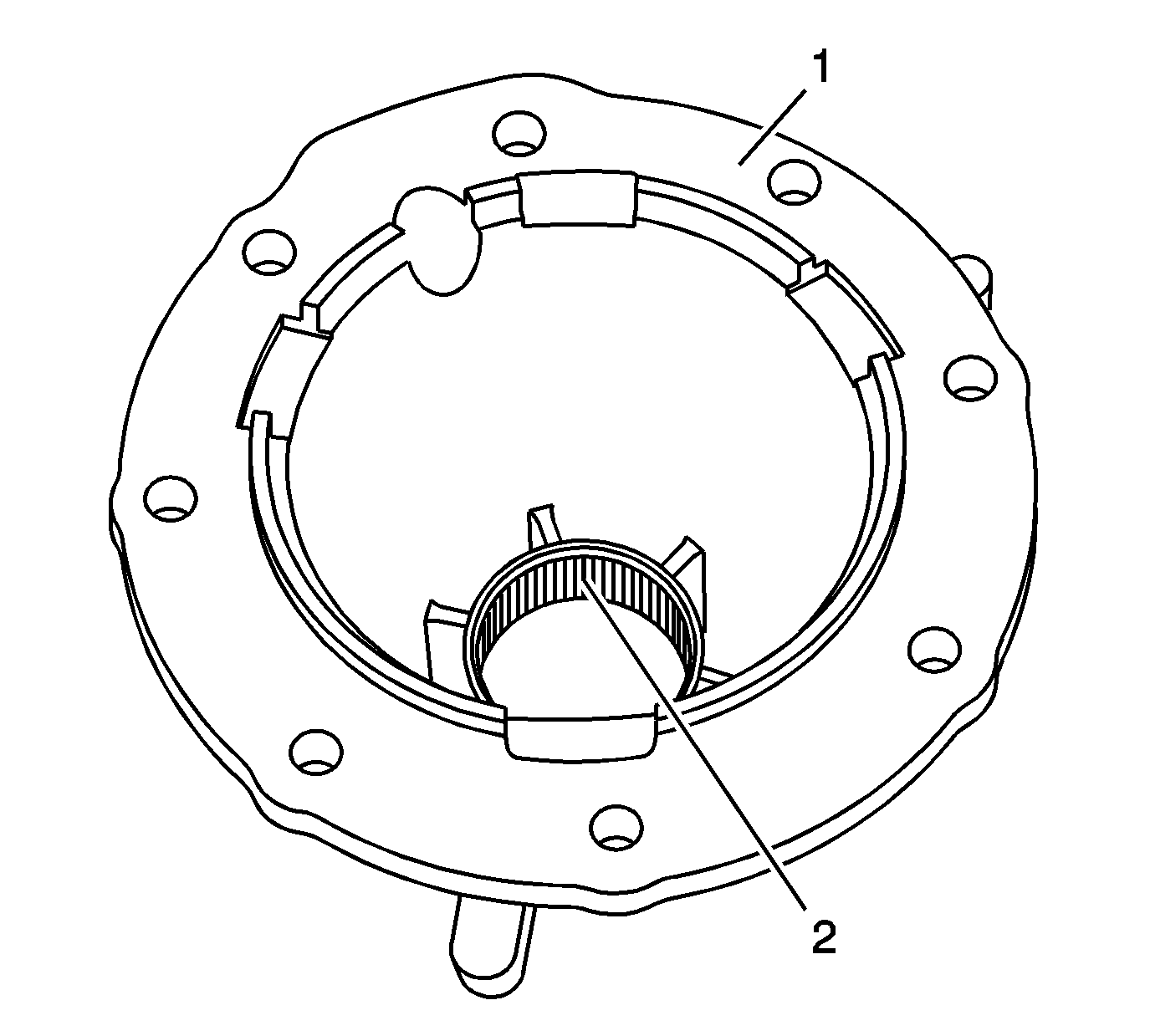
- Clean the retainer assembly in cleaning solvent and air dry.
Notice: Refer to Machined Surface Damage Notice in the Preface section.
- Remove the sealer from the retainer assembly sealing surface (1).
- Inspect the retainer assembly for being broken or cracked.
- Replace the retainer assembly if it is broken or cracked.
- Inspect the sealing surface (1) for damage.
- Repair small scratches or nicks with a soft stone.
- Inspect the rear needle bearing (2) for the following conditions:
- Replace the rear needle bearing (2) if any of the above conditions are found. Refer to
Transfer Case Disassemble
and
Transfer Case Assemble
.
- Inspect for a spun bearing bore for the rear needle bearing.
- Replace the retainer assembly if a bearing has spun.
Oil Pump
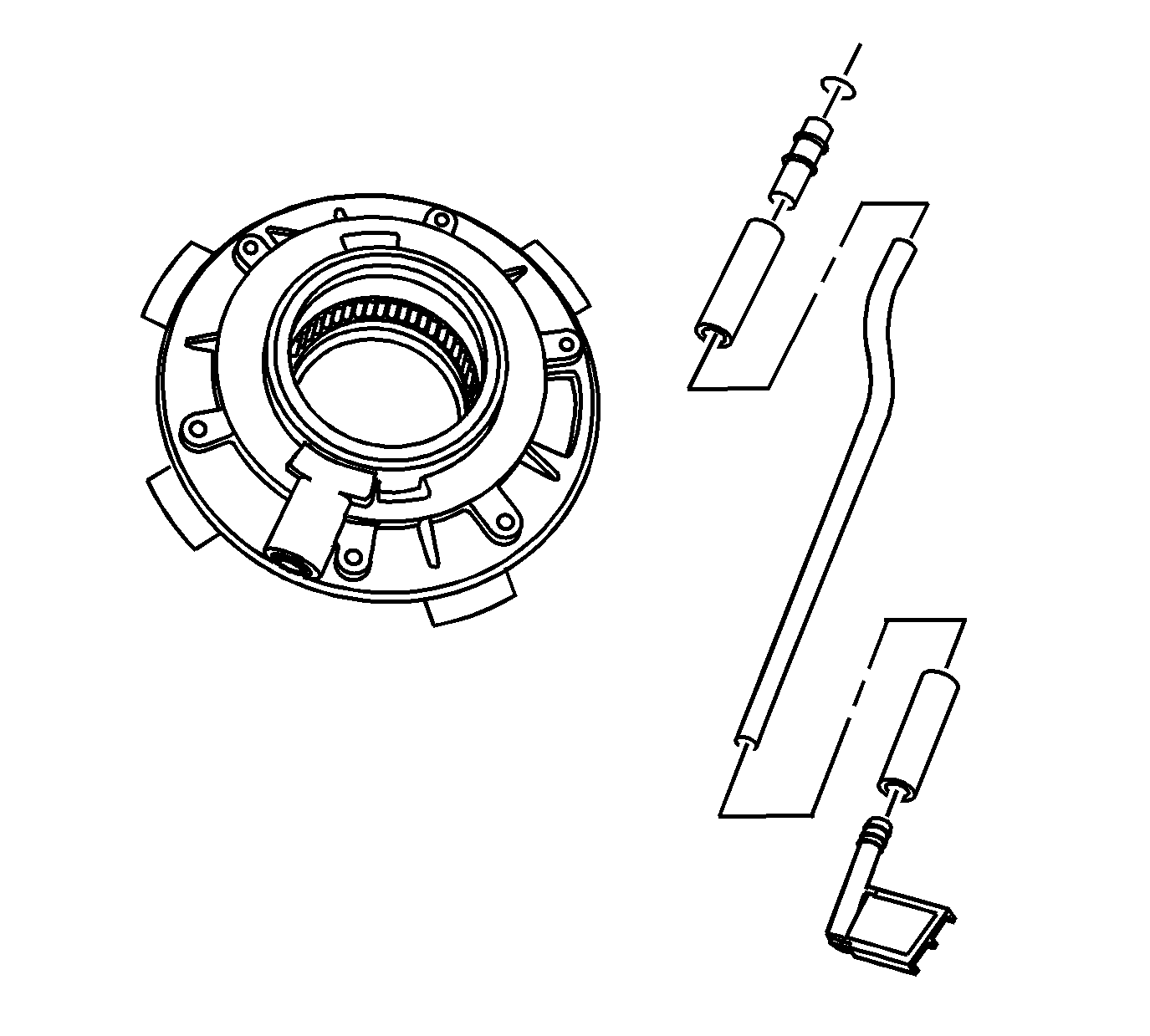
- Remove the oil pump suction pipes and the oil pump suction hoses from the oil pump screen.
- Clean the pipes, hoses, and screen in cleaning solvent and air dry.
- If the screen is embedded with debris, replace the screen.
- Inspect the hoses for cracking or tears.
- Replace the hoses if they are faulty.
- Inspect the oil pump for the oil pump gears turning without binding.
- Replace the oil pump if there is any binding. DO NOT disassemble the oil pump. The pump is serviced as an assembly.
Mainshaft
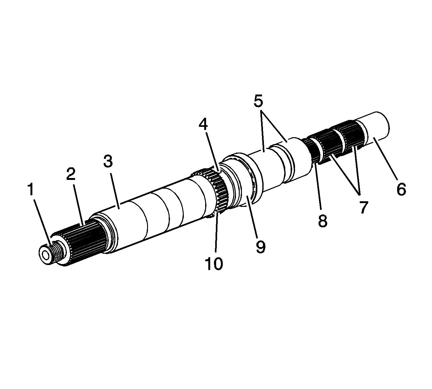
- Clean the mainshaft in cleaning solvent.
- Clean the mainshaft oil galleries (4) and air dry.
- Inspect the threads (1) for damage.
- Repair the threads (1) if damaged.
Important: Do not attempt to smooth any roughness in the bearing journals.
- Inspect the input gear pilot bearing surface (6), the drive sprocket hub surface (5), the rear output bearing surface (9) and the rear needle bearing surface (3) for the following conditions:
- Inspect the following mainshaft splines for damage or excessive wear. Witness marks at the location of the gears is normal.
| • | The rear output flange splines (2) |
| • | The oil pump splines (10) |
| • | The synchronizer hub spines (8) |
| • | The high/low range sleeve splines (7) |
- Replace the mainshaft if any of the above conditions are found.
High/Low Planetary Carrier
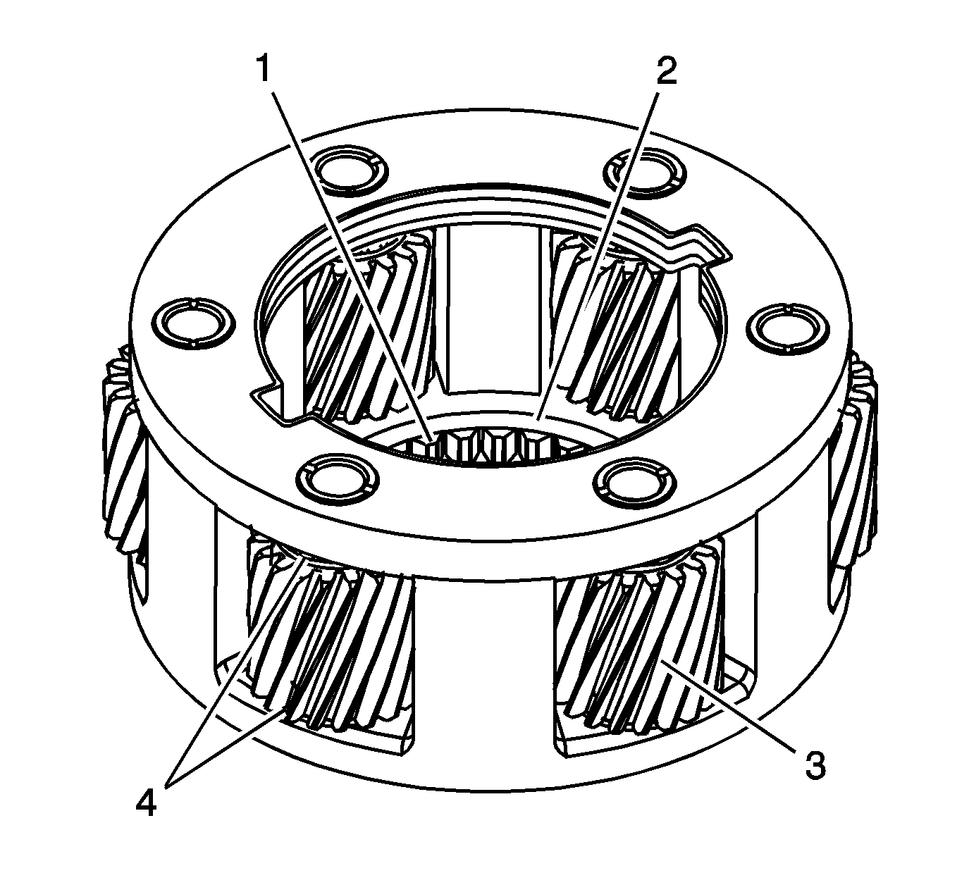
- Clean the high/low planetary carrier in cleaning solvent. Do not disassemble the
planetary carrier.
- Air dry, and ensure all cleaning solvent is removed from the bearings in the planetary gears (3). Do not spin the planetary gears with compressed air.
- Inspect the planetary gears (3) for chipped teeth.
- Inspect the planetary gears (3) for debris embedded in the root of the teeth.
- Inspect for a washer (4) being on each side of the planetary gears (3).
- Inspect the low range teeth (1) for damage or excessive wear.
- Inspect the thrust washer surface (2) for scoring or excessive wear.
- Replace the high/low planetary carrier if any of the above conditions are found.
- Inspect the input gear thrust washers for excessive wear or scoring.
- Replace the thrust washers if they are faulty.
Drive Chain and Sprockets
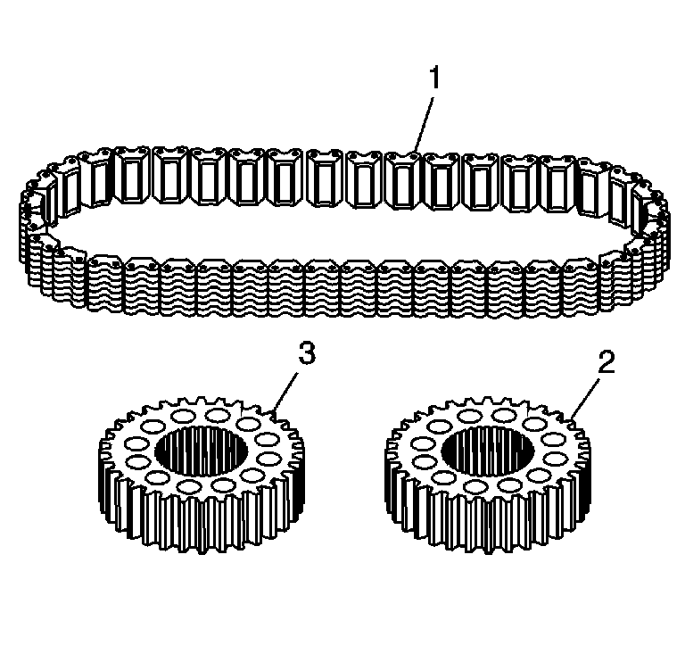
- Clean the drive chain (1), drive sprocket (3), and driven sprocket (2)
in cleaning solvent and air dry.
- Inspect the drive chain (1) for the following conditions:
| • | Debris embedded in the links |
- Replace the chain if any of the above conditions are found.
- Inspect the driven sprocket (2) and the drive sprocket (3) for the following conditions:
| • | Excessive worn gear surfaces, slight wear marks are normal |
| • | Debris embedded in the root of the teeth |
- Replace the sprocket if any of the above conditions are found. The chain and sprockets may be replaced separately.
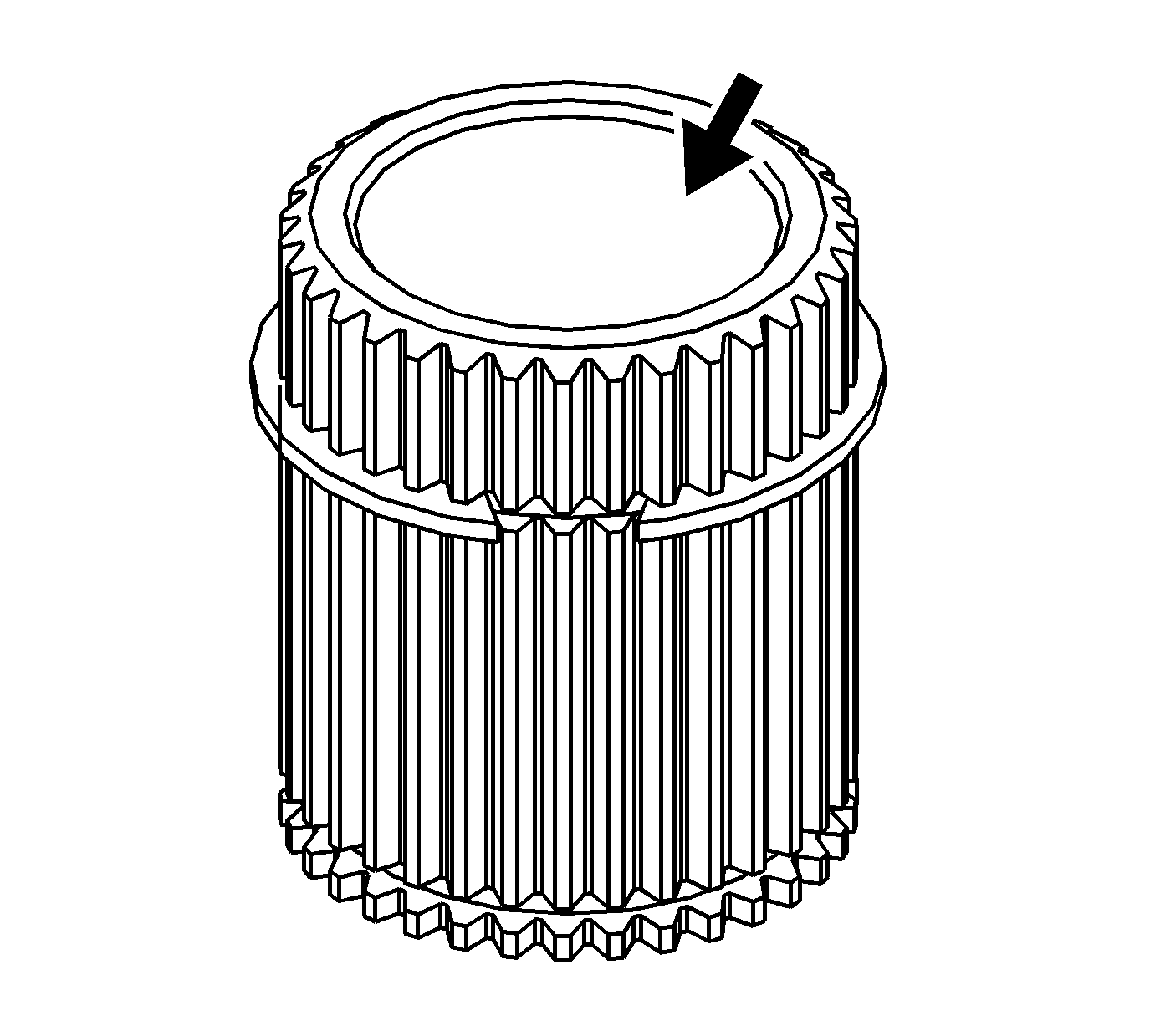
- Clean the drive sprocket hub in cleaning solvent and
air dry.
- Inspect the drive sprocket hub journal surface for the following conditions:
- Replace the drive sprocket hub if faulty.
Front Output Shaft
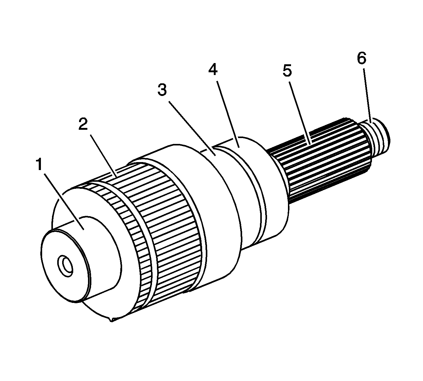
- Clean the front output shaft in cleaning solvent and air dry.
- Inspect the threads (6) for damage.
- Repair the threads (6) if damaged.
- Inspect the front output needle bearing surface (1), front bearing surface (3) and seal surface (4) for the following conditions:
- Inspect the front output shaft splines (2, 5) for damage.
- Replace the front output shaft if any of the above conditions are found.
Input Gear
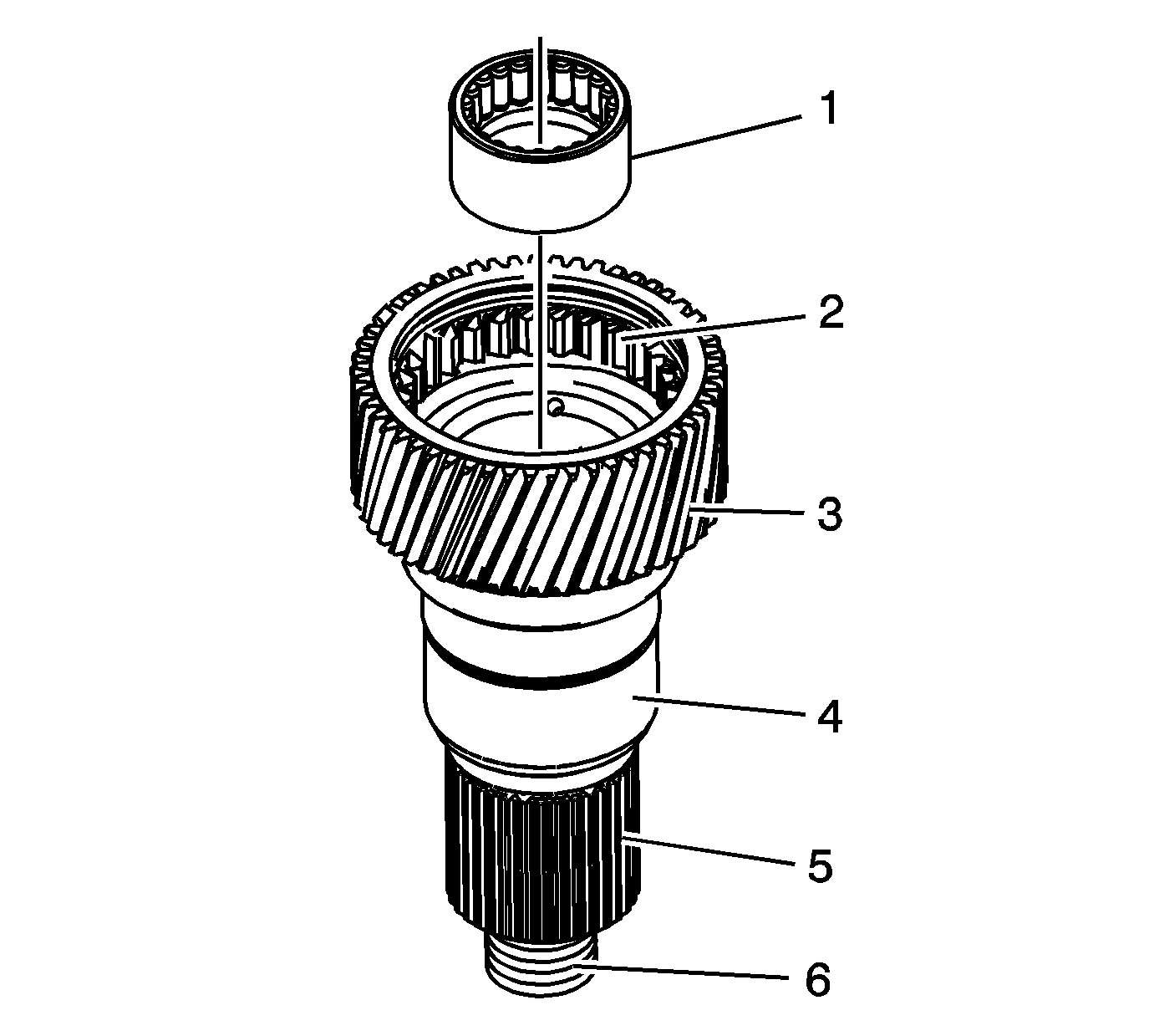
- Clean the input gear, with pilot bearing, in cleaning solvent.
- Air dry and ensure all solvent is removed from the pilot bearing.
- Inspect the threads (6) for damage.
- Repair the threads (6) if damaged.
- Inspect the pilot bearing (1) for the following conditions:
- Replace the input gear pilot bearing if any of the above conditions are found. Refer to
Transfer Case Disassemble
and
Transfer Case Assemble
.
- Inspect the input gear engagement teeth (2) for chips.
- Inspect the input gear for broken or damaged planetary teeth (3).
- Inspect the input gear for debris embedded in the root of the teeth.
- Inspect the input gear bearing surface and seal surface (4) for pitting or excessive wear.
- Inspect the input gear splines (5) for damage.
- Replace the input gear if any of the above conditions are found.
Shift System Components
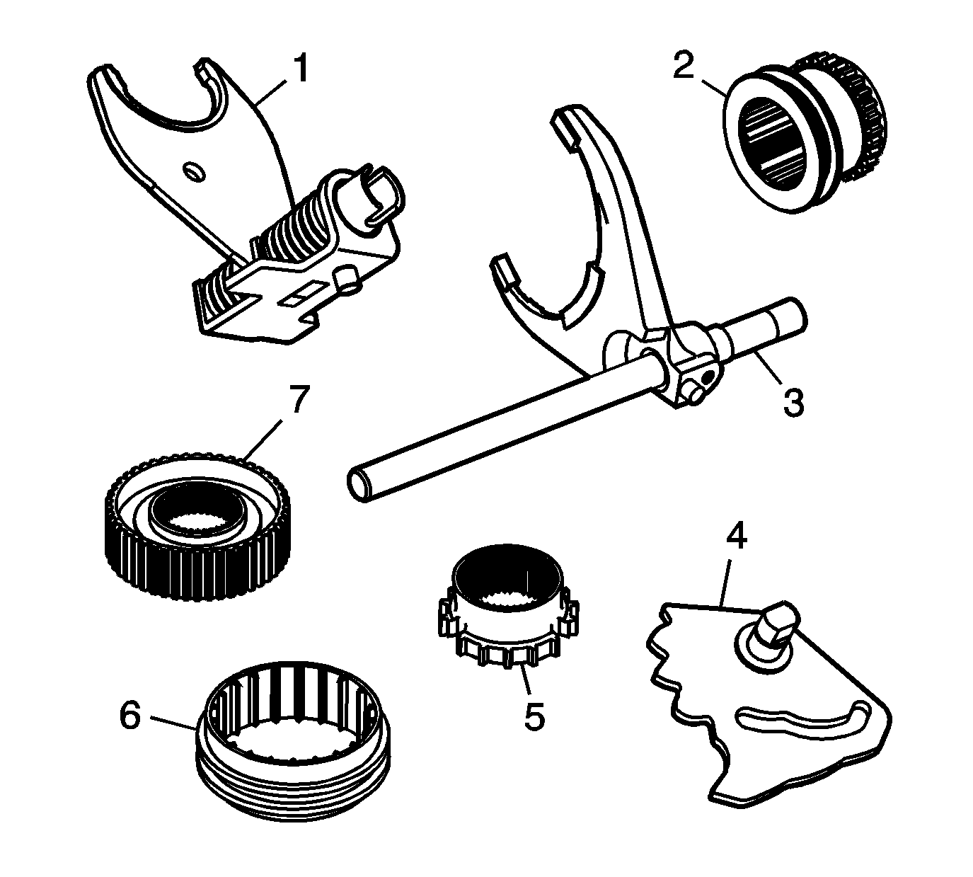
- Clean the following shift system components in cleaning solvent and air dry:
| • | The high/low range shift fork (1) |
| • | The high/low range sleeve (2) |
| • | The 2/4 wheel drive mode shift fork (3) |
| • | The sector assembly (4) |
| • | The 2/4 wheel drive synchronizer gear (5) |
| • | The synchronizer sleeve (6) |
| • | The synchronizer hub (7) |
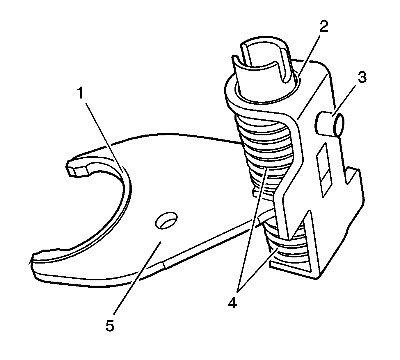
- Inspect the pads (1) on the high/low range shift fork for wear or breakage.
- Replace the pads (1) if they are worn or broken.
- Inspect the following components of the high/low range shift fork assembly for wear or damage:
- Replace the high/low range shift fork if any of the above is worn or damaged.
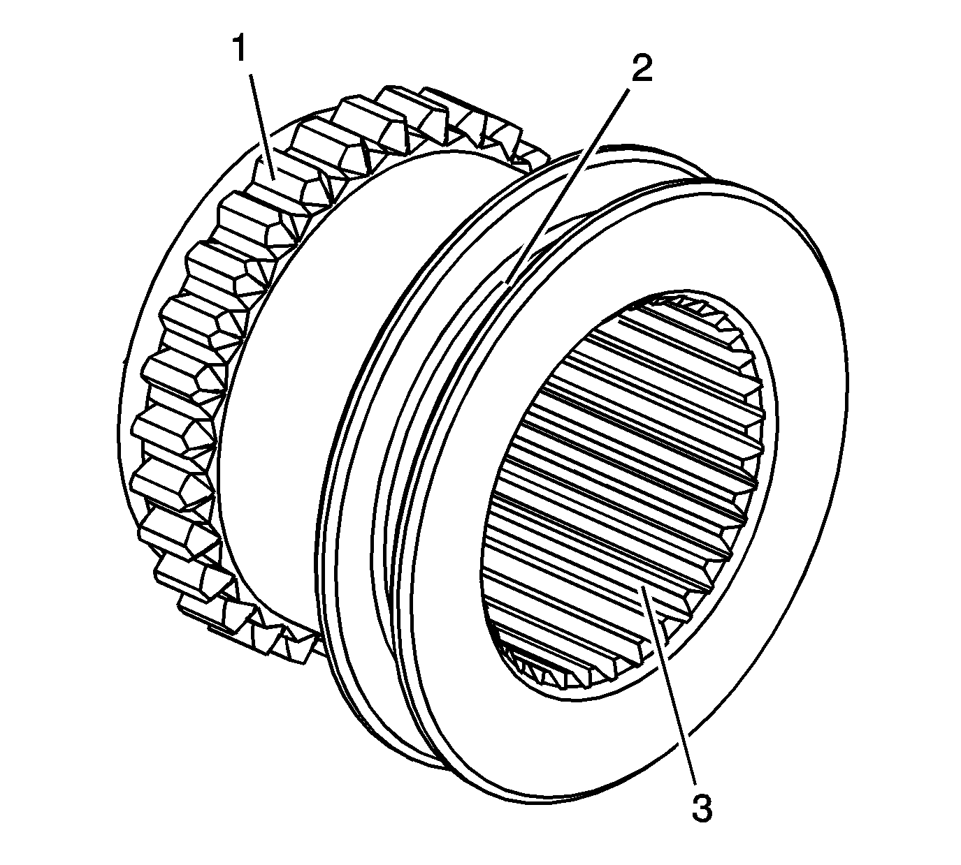
- Inspect the high/low range sleeve for chipped or excessive worn teeth (1).
- Inspect the shift fork collar (2) on the high/low range sleeve for wear.
- Inspect the inner splines (3) of the high/low range sleeve for excessive looseness on the rear output shaft.
- Replace the high/low range sleeve if the above conditions are found.
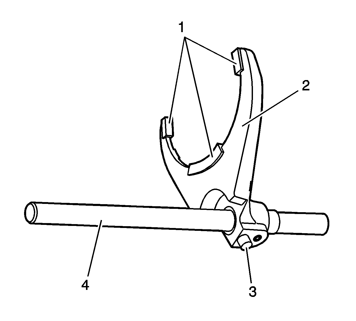
- Inspect the pads (1) on the 2/4 wheel drive mode shift fork for wear.
- Replace the pads (1) if they are worn.
- Inspect the 2/4 wheel drive mode shift fork shaft for straightness.
- Inspect the following components of the 2/4 wheel drive mode shift fork assembly for wear or damage:
- Replace the shift fork if any of the above is worn or damaged.
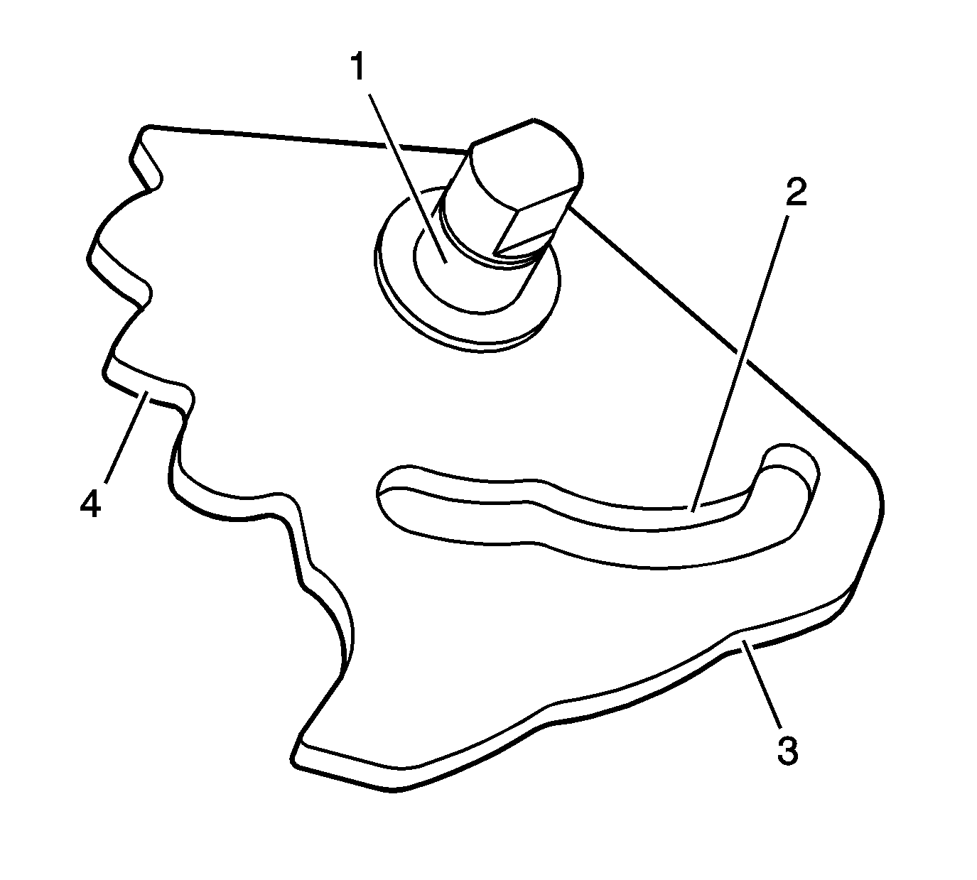
- Inspect the bearing (1) and the seal surface on the sector shaft for the
following conditions:
- Inspect the high/low range shift fork roller slot (2) on the sector assembly for wear or roughness.
- Inspect the 2/4 wheel drive mode shift fork cam lobes (3) on the sector assembly for wear or roughness.
- Inspect the shift detent plunger cam lobes (4) for wear or roughness.
- Replace the sector assembly if any of the above conditions are found.
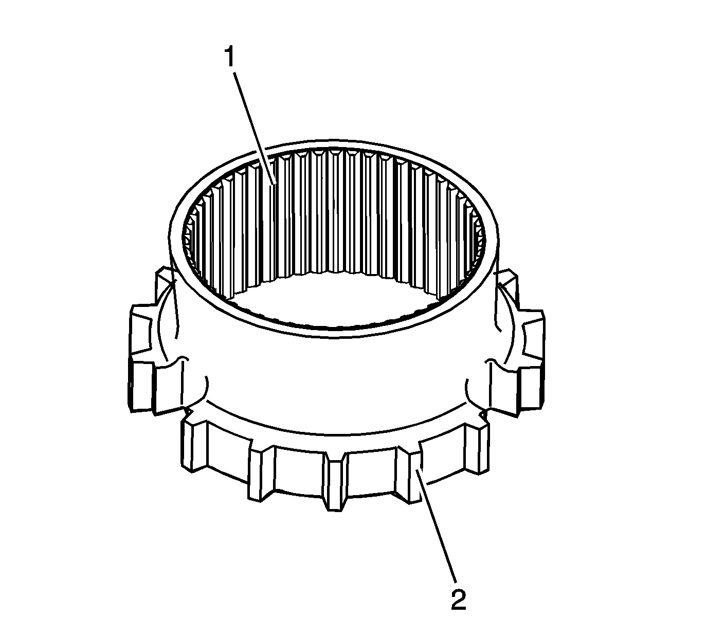
- Inspect the 2/4 wheel drive synchronizer gear for chipped or excessive worn teeth (2).
- Inspect the inner splines (1) of the 2/4 wheel drive synchronize gear for excessive looseness on the drive sprocket hub.
- Replace the 2/4 wheel drive synchronizer gear if the above conditions are found.
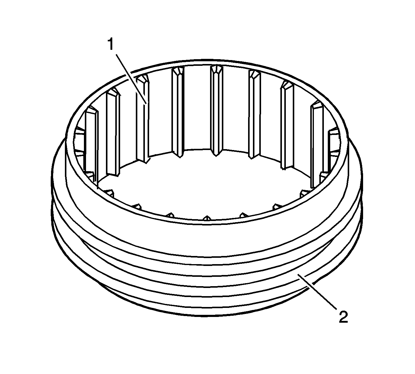
- Inspect the synchronizer sleeve for the following conditions:
| • | Wear on the engagement teeth (1) |
- Replace the synchronizer sleeve if any of the above are worn.
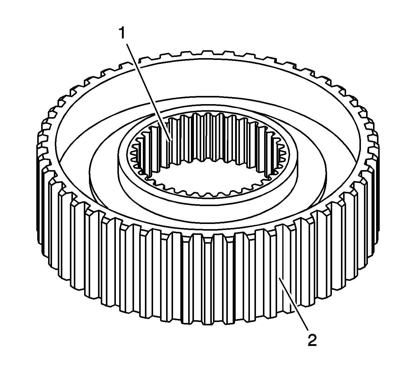
- Inspect the synchronizer hub for the following conditions:
| • | Loose fit on the mainshaft |
| • | Wear on the splines (1) |
| • | Wear on the engagement teeth (2) |
- Replace the synchronizer hub if any of the above is worn.


