Air Drum Brake Adjustment Pushrod Stroke Measurement
Check your maintenance schedule for the recommended service intervals.
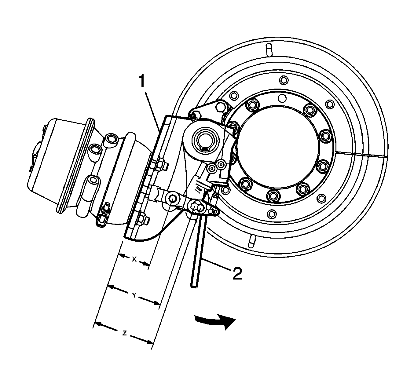
Measure the pushrod stroke in order to determine if the brakes are acceptably
adjusted (1). The pushrod travel should be less than the maximum allowable stroke
listed in the Dimensional Specifications Table. Refer to
Air Drum Brake Component Specifications
.
Measurement Procedure
The stroke is the difference between the released air brake automatic slack
adjuster position and the applied air brake automatic slack adjuster position. The
applied position must be measured at 550-620 kPa (80-90 psi)
air pressure in the brake chamber assemblies when the brakes are fully applied.
- Start the engine to increase the air pressure to 690 kPa (100 psi)
if necessary.
- Stop the engine. Apply and release the brakes to decrease the air pressure
to 690 kPa (100 psi) if necessary.

- Check the dual air pressure gauge in order
to ensure the correct air pressure. Verify that the air pressure in the air reservoirs
is 690 kPa (100 psi) under the following conditions:
| • | The rear air brake chambers, spring brake chamber section, are released |
- For (X) measure the distance between the brake chamber assembly
mounting surface and the center of the air brake chamber clevis pin on all of the
brakes.
- Have an assistant apply and hold one full brake application.
- For (Z) measure the distance between the brake chamber assembly mounting
surface and the center of the air brake chamber clevis pin on all of the brakes with
the brakes applied at 550-620 kPa (80-90 psi).
- Release the brakes.
- Calculate the adjusted air brake chamber stroke at each brake using the
following method:
| 8.1. | Subtract the dimension in measurement (X) from the dimension in
measurement (Z). |
| 8.2. | The difference between the two dimensions is the adjusted air brake chamber
stroke. The adjusted air brake chamber stroke must not be greater than the stroke
length shown in the Dimensional Specifications Table. Refer to
Air Drum Brake Component Specifications
. |
Air Drum Brake Adjustment Arvin-Meritor/Gunite
Check your maintenance schedule for the recommended service intervals.
Measure the pushrod stroke in order to determine if the brakes are acceptably
adjusted (1). The pushrod travel should be less than the maximum allowable stroke
listed in the Dimensional Specifications Table. Refer to
Air Drum Brake Component Specifications
.
- Block the wheels.
- Perform the Push Rod Stroke Measurement procedure to see if adjustment
is needed.

Important: Automatic slack adjusters should never be
manually adjusted in an effort to correct excessive chamber pushrod stroke. Manual
adjustment of the automatic slack adjuster can result in a degradation of slack adjuster
performance over time. If pushrod stroke is out of adjustment, determine root cause
of excess stroke by checking the chamber clevis, clevis pins, brake return springs,
camshaft bracket, camshaft bushings, and related foundation brake components for wear
or damage. Replace any worn or damaged components. Also ensure that the clevis jam
nut is not loose. If the pushrod stroke is still out of adjustment, replace the slack
adjuster.
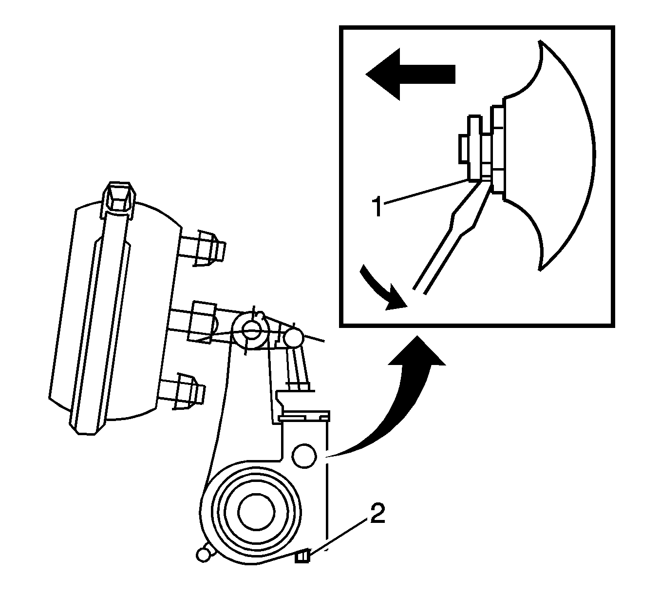
- To adjust the chamber stroke or slack adjuster setting, perform the following:
| 3.1. | Disengage the pawl (1) by using a flat-bladed tool to lift
the button on the pawl assembly at least 1/32 inch. |
| 3.2. | Turn the manual adjustment nut (2) 1/8 turn counterclockwise
until the linings touch the drum. |
| 3.3. | Back off the linings by turning the manual adjuster nut (2) a 1/2 turn
in the opposite direction. |
| 3.4. | Rotate the drum to check for clearance. |
| 3.5. | Remove the flat-bladed tool from the pawl (1). |


