Removal Procedure
Caution: Refer to SIR Caution in the Preface section.
- Disable the SIR system. Refer to
SIR Disabling and Enabling
in SIR.
- Remove the steering wheel. Refer to
Steering Wheel Replacement
.
- Remove the shift lever. Refer to
Shift Lever Replacement
.
- Remove the ignition lock cylinder. Refer to
Ignition Lock Cylinder Replacement
.
- If tilt column, remove the steering column tilt head components.
Refer to
Turn Signal Cancel Cam and Upper Bearing Inner Race Replacement
.
- If standard column, remove the steering column components. Refer
to
Turn Signal Cancel Cam and Upper Bearing Thrust Washer
.

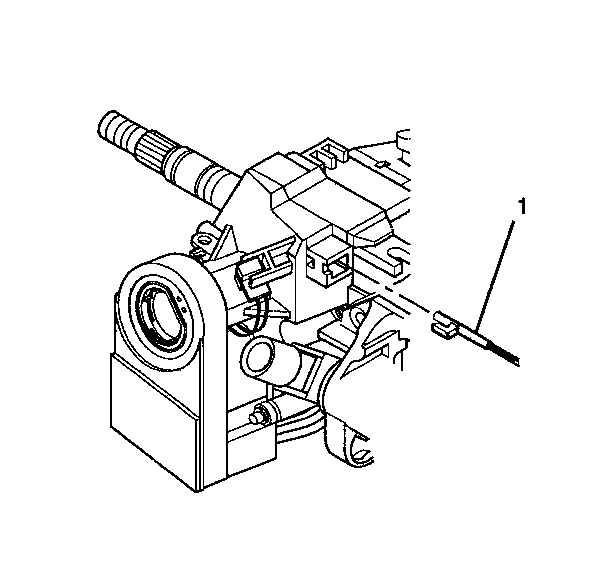
- If necessary, remove the
park lock cable assembly (1) from the ignition lock cylinder case assembly.
| 7.1. | Place the lock cylinder in the OFF-LOCK position. |
| 7.2. | Place the shift lever into the PARK position. |
| 7.3. | Insert a small screwdriver into the slot on the ignition lock
cylinder case assembly. Push against the locking tab on the end of the park
lock cable assembly (1). |
| 7.4. | Disconnect the park lock cable assembly (1) from the ignition
lock cylinder case assembly. |

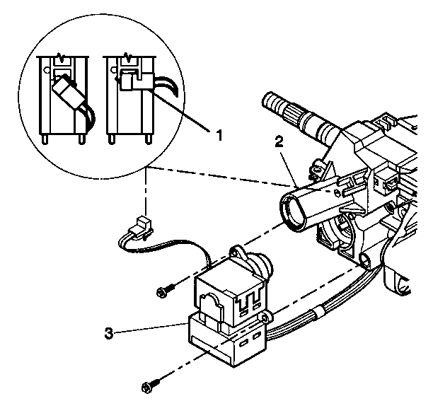
- Rotate the key alarm connector (1)
90 degrees.
- Pull the key alarm connector (1) out of the ignition lock
cylinder case assembly (2).
- Remove the 2 tapping screws from the ignition switch (3).
- Remove the ignition switch (3) from the ignition lock cylinder
case assembly (2).
- Let the ignition switch (3) hang freely.

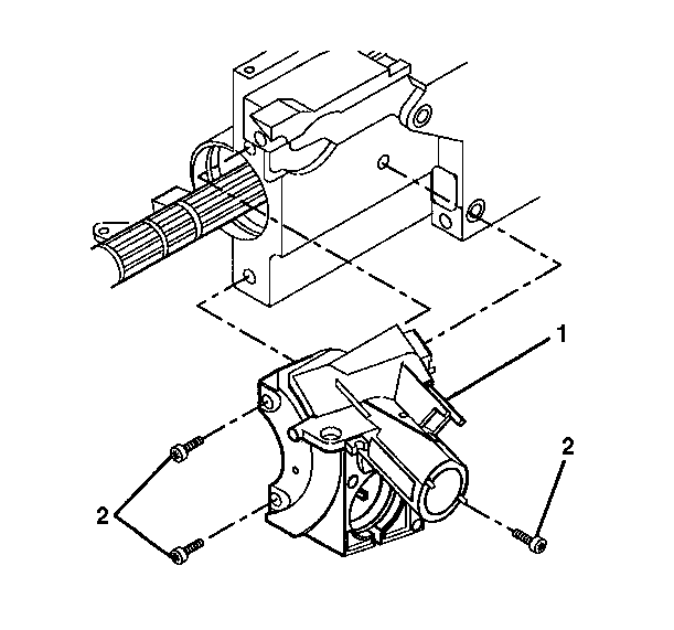
- Remove the 3 pan
head tapping screws (2) from the ignition lock cylinder case assembly (1).
- Remove the ignition lock cylinder case assembly (1) from
the steering column tilt head assembly.
Installation Procedure
Notice: Refer to Fastener Notice in the Preface section.

- Install the ignition lock
cylinder case assembly (1) onto the steering column tilt head assembly.
- Screw the 3 pan head tapping screws (2) into the ignition
lock cylinder case assembly.
Tighten
Tighten the screws to 7 N·m (62 lb in).

- Install the ignition switch
assembly (1) onto the ignition lock cylinder case assembly (2).
- Screw the 2 tapping screws into the ignition switch (1).
Tighten
Tighten the tapping screws to 1.5 N·m (13 lb in).
- Install the key alarm connector (3) onto the ignition lock
cylinder case assembly (2) by doing the following:
| 4.1. | Push the key alarm connector (1) into the ignition lock
cylinder case assembly (2). |
| 4.2. | Rotate the key alarm connector 90 degrees so that the key
alarm connector locks into place. |

Caution: Improper routing of the wire harness assembly may damage the inflatable
restraint steering wheel module coil. This may result in a malfunction of
the coil, which may cause personal injury.
- If necessary, connect the park lock cable assembly (1):
| 5.1. | Place the lock cylinder in the ACCESSORY position. |
| 5.2. | Place the gear shift lever into the PARK position. |
| 5.3. | Press the locking tab on the end of the park lock cable assembly (1)
into the slot in the ignition lock cylinder case assembly. |
- If standard column, install the steering column components. Refer
to
Turn Signal Cancel Cam and Upper Bearing Thrust Washer
.
- If tilt column, install the steering column tilt head components.
Refer to
Turn Signal Cancel Cam and Upper Bearing Inner Race Replacement
.
- Install the ignition lock cylinder. Refer to
Ignition Lock Cylinder Replacement
.
- Install the shift lever. Refer to
Shift Lever Replacement
.
- Install the steering wheel. Refer to
Steering Wheel Replacement
.
- Enable the SIR system. Refer to
SIR Disabling and Enabling
in SIR.


