Removal Procedure
- Remove vehicle components only if necessary, in order to provide adequate clearance for transmission removal.
- Remove the engine cover. Refer to
Engine Cover Replacement
.
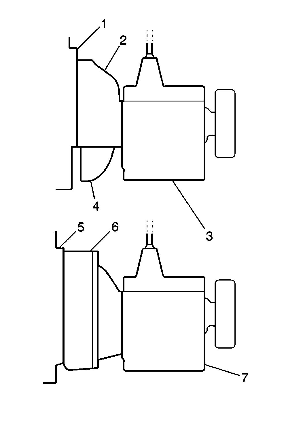
- The vehicle will be equipped with one of the following:
| • | Apron-type flywheel housing (2) |
| • | SAE type flywheel housing (6) |
| - | The apron-type flywheel housing (2) has a sheet metal access cover (4) which allows for inspection of the clutch and flywheel. |
| - | The SAE type flywheel housing (6) surrounds the entire clutch flywheel. |
- Transmission replacement procedures differ slightly between the two types of housings.
- Block the front and rear wheels.
- Ensure that the transmission is in neutral.
Caution: Unless directed otherwise, the ignition and start switch must be in the OFF or LOCK position, and all electrical loads must be OFF before servicing
any electrical component. Disconnect the negative battery cable to prevent an electrical spark should a tool or equipment come in contact with an exposed electrical terminal. Failure to follow these precautions may result in personal injury and/or damage to
the vehicle or its components.
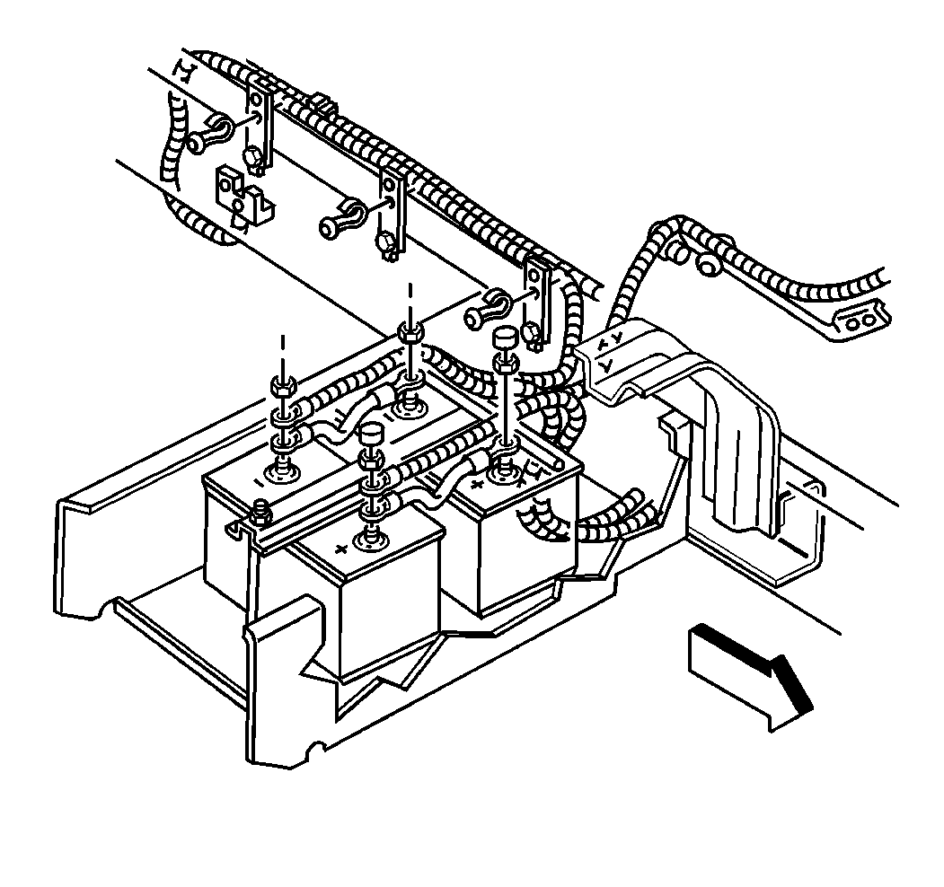
- Disconnect the negative battery cable. Refer to
Battery Negative Cable Disconnection and Connection
.
- Drain the transmission fluid. Refer to
Transmission Oil Changing
.
- Remove the control lever and/or boot. Refer to
Control Lever and/or Boot Replacement
.
- Remove the transmission air shift harness, if equipped. Refer to
Transmission Air Shift Harness Replacement
.
- Remove the clutch cable bracket bolts and reposition the clutch cable bracket and cable. Refer to
Clutch Cable Return Spring and/or Bracket Replacement
.
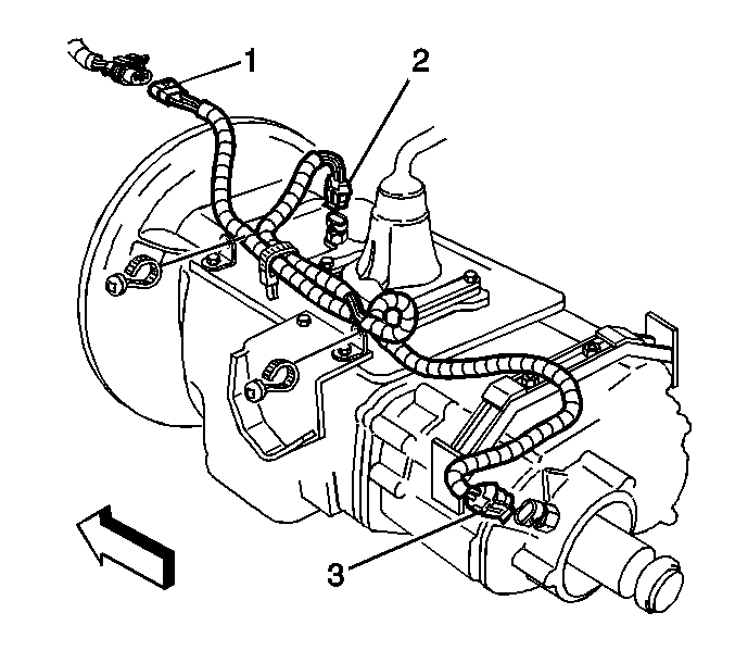
- Disconnect the engine harness electrical connectors from the transmission connector (1) typical.
- If equipped, remove the park brake cable from the transmission. Refer to
Park Brake Cable Replacement
.
- Remove the propeller shaft. Refer to
Two-Piece Rear Propeller Shaft Replacement
,
One-Piece Rear Propeller Shaft Replacement
, or
Three-Piece Rear Propeller Shaft Replacement
.
- If equipped, remove the power take-off (PTO) and controls. Install a protective cover over the PTO opening.
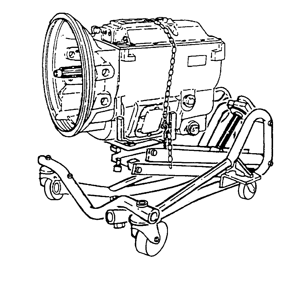
Important: When removing or installing the transmission, use a transmission dolly jack in order to support the weight of the transmission. Fasten safety chains over the top and to both sides of the dolly.
- Position the dolly jack under the transmission. Adjust the dolly jack in order to support the weight of the transmission.
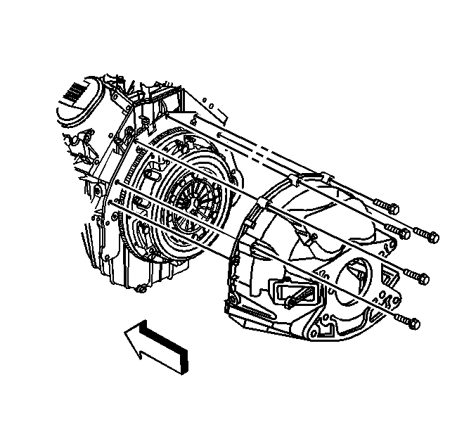
- If equipped with the apron-type flywheel housing, remove the flywheel housing cover bolts and cover.
- If equipped with a apron-type flywheel housing, remove the clutch fork return spring bracket, caution tag, and housing cover extension bolts.
- If equipped with the apron-type flywheel housing, remove the flywheel housing bolts.
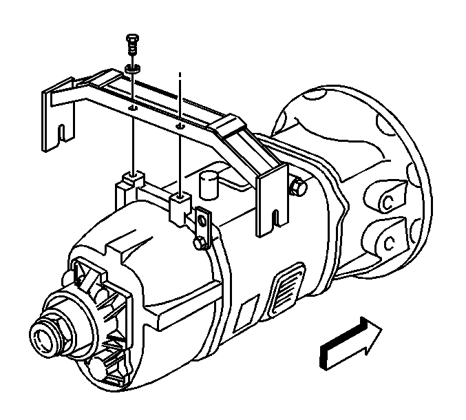
- If equipped with a transmission support, remove the transmission support. Refer to
Transmission Mount Bracket Replacement
.
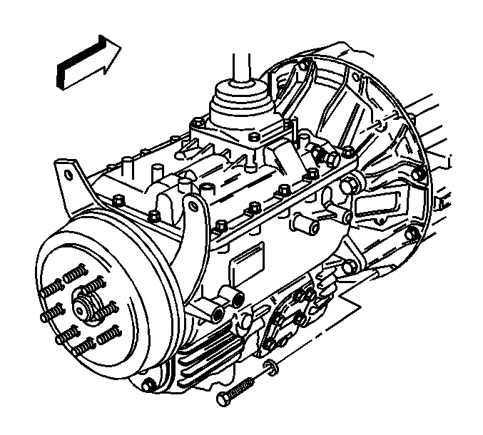
- If equipped with the SAE type flywheel housing, remove the transmission bolts.
Notice: When removing the transmission, do not allow the weight of the transmission
to hang on the clutch disc hub. The clutch disc will become distorted and
seriously affect the operation of the clutch.
- Move the transmission straight back from the engine, keep the mainshaft in alignment with the clutch disc hub.
- When the transmission is free from the engine, lower and remove the transmission.
Installation Procedure

- Shift the transmission into high gear.
- With the transmission mounted to a suitable dolly, move the transmission into position under the vehicle.
- Rotate the output shaft to align the main drive gear shaft with the clutch disc hub.
- Move the transmission forward, guiding the main drive gear shaft into the clutch disc hub.
- Install the transmission.
| • | Avoid springing the clutch when installing the transmission. |
| • | Do not allow the transmission to drop or hang unsupported in the splined hub of the clutch disc. |
- If equipped with brackets, install the brackets and the transmission bolts.
Notice: Refer to Fastener Notice in the Preface section.
- If equipped with the SAE number 2 flywheel housing, install the exhaust manifold front pipe bracket and transmission bolts.
Tighten
Tighten the transmission bolts to 50 N·m (37 lb ft).
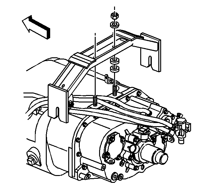
- If equipped, install the transmission support. Refer to
Transmission Mount Bracket Replacement
.

- If equipped with the apron-type flywheel housing, install the flywheel housing bolts.
Tighten
Tighten the bolts to 50 N·m (37 lb ft).
- If equipped with the apron-type flywheel housing, install the flywheel housing cover and bolts.
Tighten
Tighten the bolts to 25 N·m (18 lb ft).
- If equipped, remove the protective cover over the PTO opening. Install the PTO and controls.
- Install the propeller shaft. Refer to
Two-Piece Rear Propeller Shaft Replacement
,
One-Piece Rear Propeller Shaft Replacement
, or
Three-Piece Rear Propeller Shaft Replacement
.
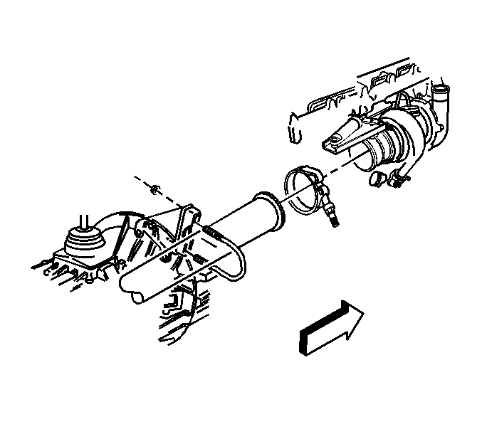
- If equipped with RPO K40, perform the following:
| • | Install the exhaust manifold front pipe. |
| • | Install the U-bolt and nuts. |
Tighten
Tighten the nuts to 24 N·m (18 lb ft).
| • | Tighten the exhaust manifold front pipe clamp nut. |
Tighten
Tighten the nut to 10 N·m (89 lb in).
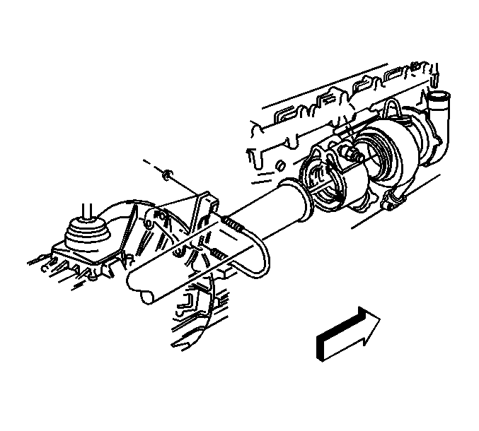
- If equipped without PRO K40, perform the following:
| • | Install the exhaust manifold front pipe. |
| • | Install the U-bolt and nuts. |
Tighten
Tighten the nuts to 24 N·m (18 lb ft).
| • | Install the exhaust manifold front pipe clamp nut. |
Tighten
Tighten the nut to 10 N·m (89 lb in).
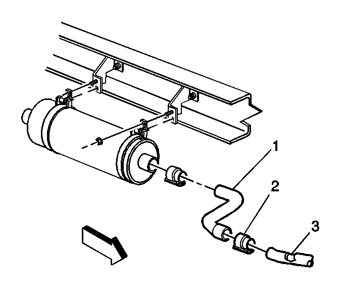
- If equipped, tighten the band clamp (2) joining the exhaust manifold front (3),
and rear (1) pipes.
- If equipped, install the muffler. Refer to
Muffler Replacement
.

- Connect the engine harness electrical connector to the transmission connector (1) typical.
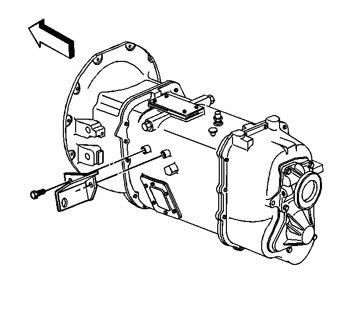
- Install and position the clutch cable bracket and cable. Refer to
Clutch Cable Return Spring and/or Bracket Replacement
.
- Install the transmission air shift harness. Refer to
Transmission Air Shift Harness Replacement
.
- Install the control lever and/or boot. Refer to
Control Lever and/or Boot Replacement
.
- Fill the transmission fluid. Refer to
Transmission Oil Changing
.
- Install the engine cover. Refer to
Engine Cover Replacement
.

- Connect the negative battery cable. Refer to
Battery Negative Cable Disconnection and Connection
.


