| • | J 43266
Injector Sleeve Installer |
| • | J 43267
Valve Stem Seal Installer |
| • | J 43272
Valve Guide Remover and Installer |
Valve Seat
Important:
| • | The valve seats must be properly reconditioned. The valves must be precisely seated for the engine to deliver proper power and performance. Good contact between each valve and its seat in the cylinder head ensures that the heat in the valve head
will be properly dispersed. |
| • | When grinding the valve seats, follow the recommendations of the equipment manufacturer in order to attain the proper results. |
| • | The valve guide bores must be clear of carbon and dirt in order to ensure the proper centering of the pilot in the valve guide. The correct seat angle is 89 degrees 45 minutes for exhaust, 119 degrees 45 minutes
for intake. |
| • | If too much material is removed from the valve seat, the valve install depth may become too excessive. If this occurs, replace the valve seat. |
| • | Replace any valves that are warped or pitted. Replace any valve stems which show excessive wear. |
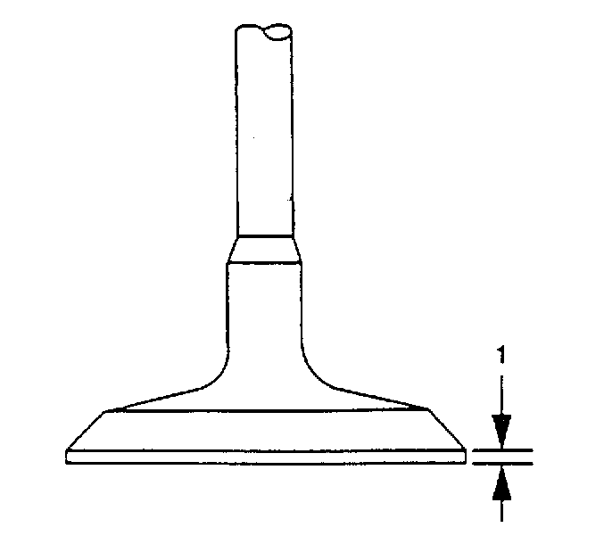
- Measure the valve margin thickness (1).
Specifications
| • | Measurement for intake valves: 1.88 mm (0.074 in) |
| • | Measurement for exhaust valves: 1.75 mm (0.0689 in) |
- Measure the valve face angle.
Specifications
| • | Face angle for the intake valve: 30 degrees. |
| • | Face angle for the exhaust valve: 45 degrees. |
Valve Guide Replacement
- Place the cylinder head on wooden blocks with the combustion chambers facing up.
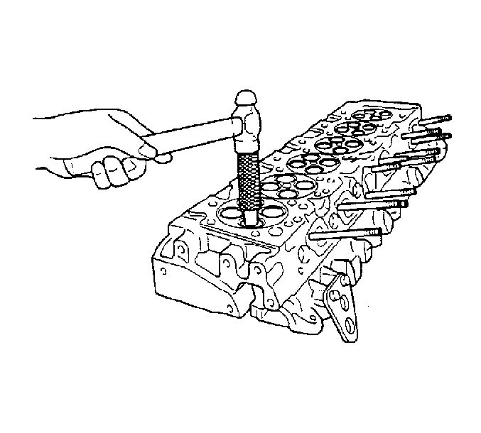
- Using the
J 43272
, drive the valve guide out.
- Clean the valve guide bore in the cylinder head.
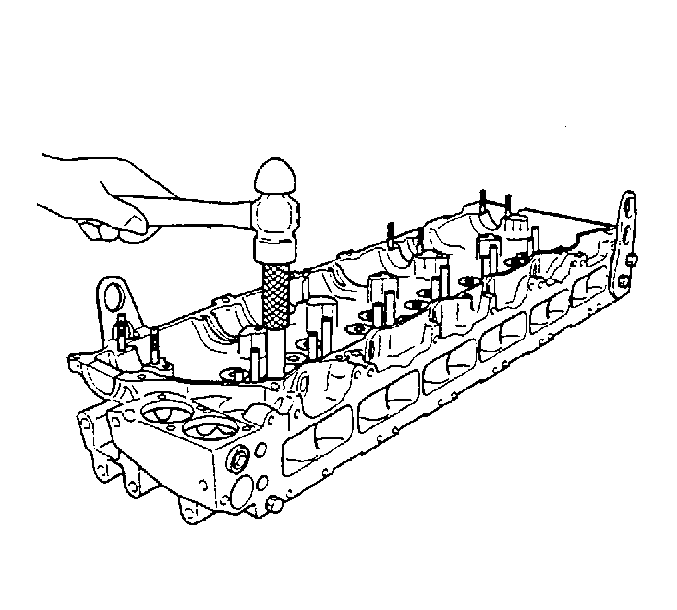
- Install the new valve guide with
J 43272
, valve guide installer.
- Measure the distance from the top of the valve guide to the cylinder head surface. The proper distance is 19 mm (0.7480 in). The
J 43272
is supplied with an installer designed to install
the valve guide to the proper depth.
Valve Seat Replacement
- Grind the valve seat (intake and exhaust) until the seat measures 0.5-1 mm (0.0196-0.04 in) thick.
- Remove the valve seat with a pry tool.
- Thoroughly clean the valve seat counter bore in the cylinder head before installing the new seat.
- Press the new valve seat into the cylinder head.
Important: When a new valve seat and new valve are used together, the installed depth should be 0.65-1.1 mm (0.0255-0.0433 in). The installed depth should not be any greater than 2.5 mm (0.098 in)
for the intake valve, and 2.8 mm (0.110 in) for the exhaust valve.
- Grind the valve seat.
Valve Lapping
The valves should be lapped just before the final assembly to assure a good valve seal.
- Apply Prussian blue dye or equivalent to the valve seat.
- Insert the valve into the proper port.
- Rotate the valve lightly, then remove.
Important: The valve seat width will be indicated by the mark on the valve face.
- Inspect the valve face.
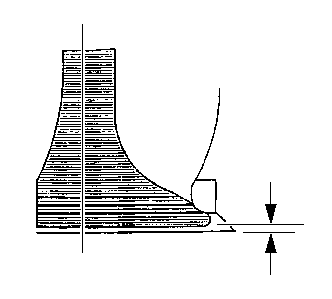
Important: The contact area should be centered on the valve face. If not, check the condition of the valve seat and repair, as needed.
- Measure the valve seat width.
Specifications
| • | Intake valve should be: 2.5 mm (0.098 in) |
| • | Exhaust valve should be: 2.0 mm (0.079 in) |
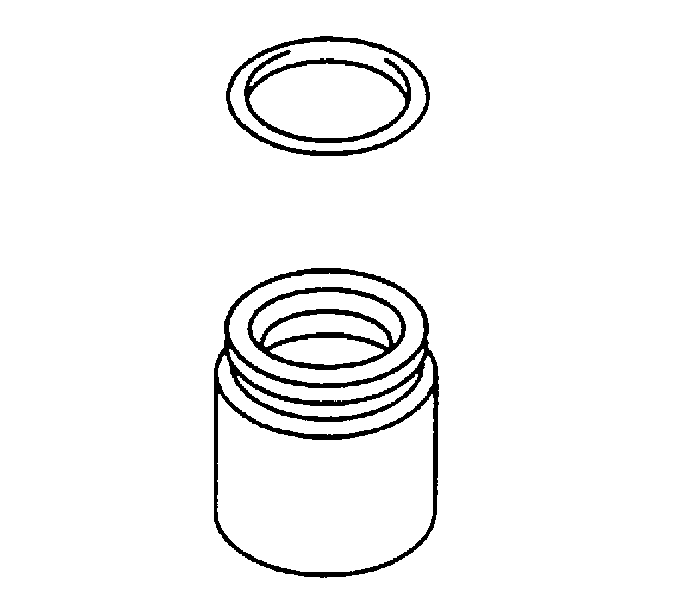
- Repeat steps 1-5 on the remaining valves.
- Clean all the Prussian blue dye from the valves and the valve seats.
- Apply a medium valve lapping compound to the valve.
- Lap the valve until a light gray ring appears all the way around the valve face.
- Thoroughly clean all the valve lapping compound from the valve and valve seat.
- Repeat this procedure on the remaining valve and valve seats.
Valve Seal Installation
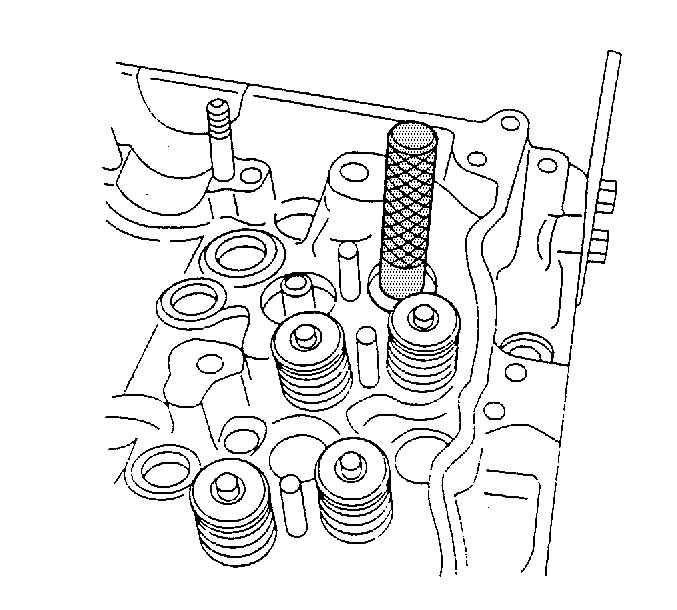
- Lubricate the valve stem seal with clean engine oil.
- Install the valve stem seal using the
J 43267
.
Injector Sleeve Replacement
- Place the cylinder head on wooden blocks with the combustion chambers facing up.
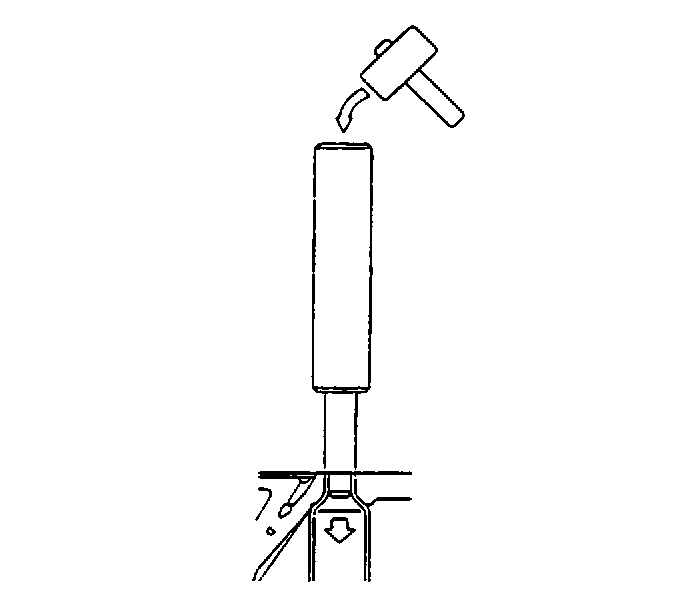
- Remove the injector sleeve with the
J 43265
.
- Clean the injector sleeve bore in the cylinder head.
- Install the O-ring (1) to the new injector sleeve.
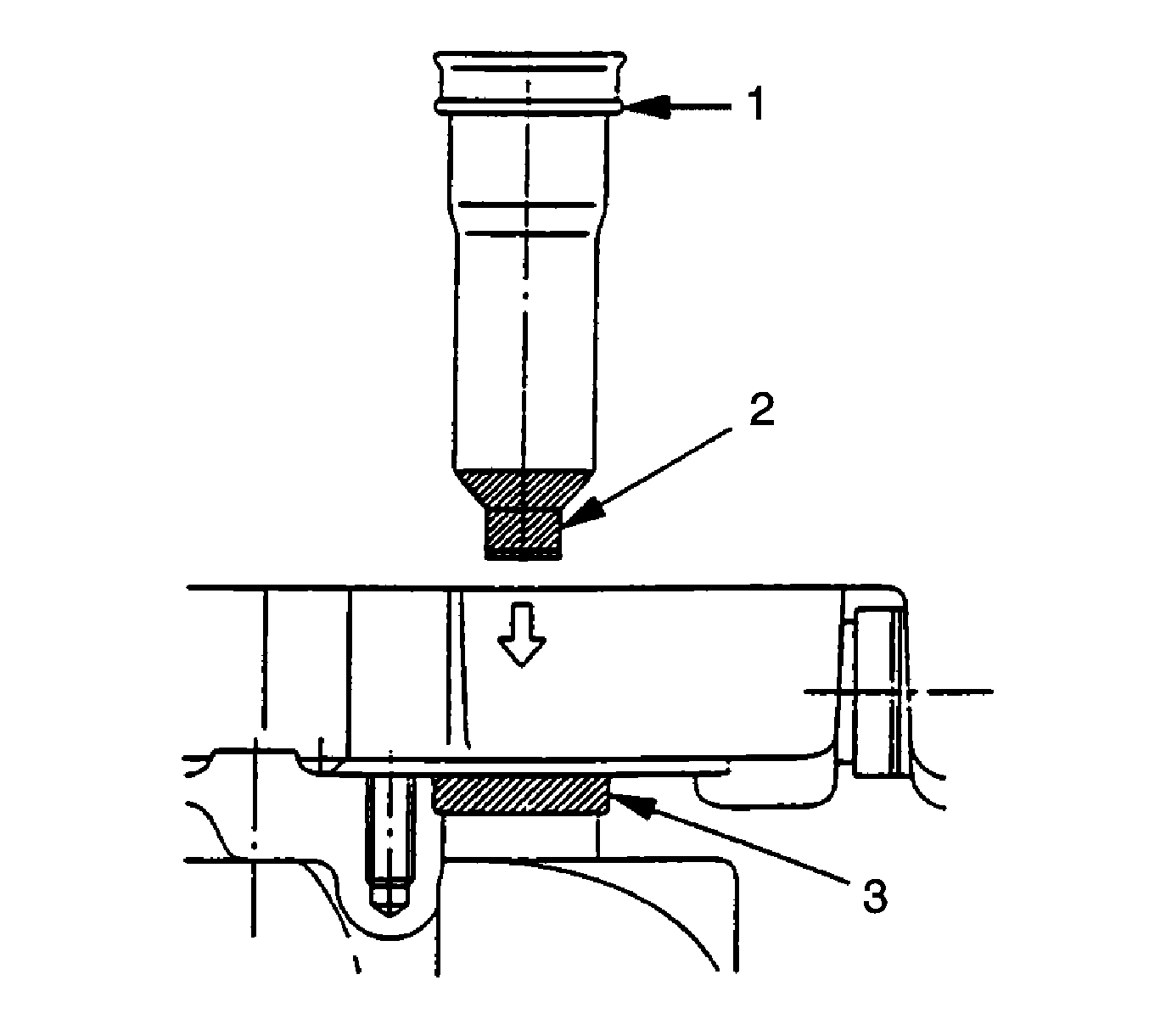
- Apply LT 620 high temperature sealant to the new injector sleeve (2) and cylinder head injector
sleeve bore (3) as shown in the illustration.
- Insert the injector sleeve to cylinder head.
- Use the injector clamp bolt to clamp the injector sleeve with the
J 43266
.
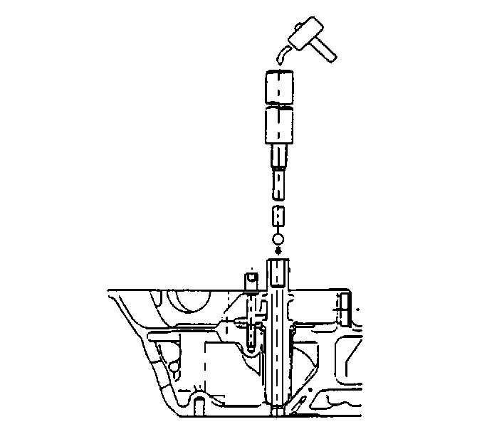
- Put the ball bearing, outside diameter 9.525 mm (3.8 in), into the injector sleeve and set tool
J 43266
.
- Strike out the ball bearing.


