Removal Procedure
- Disconnect the negative battery cable at the battery. Refer to Battery Negative Cable Disconnection and Connection .
- Remove the air inlet pipe from the turbocharger and the charge air cooler .
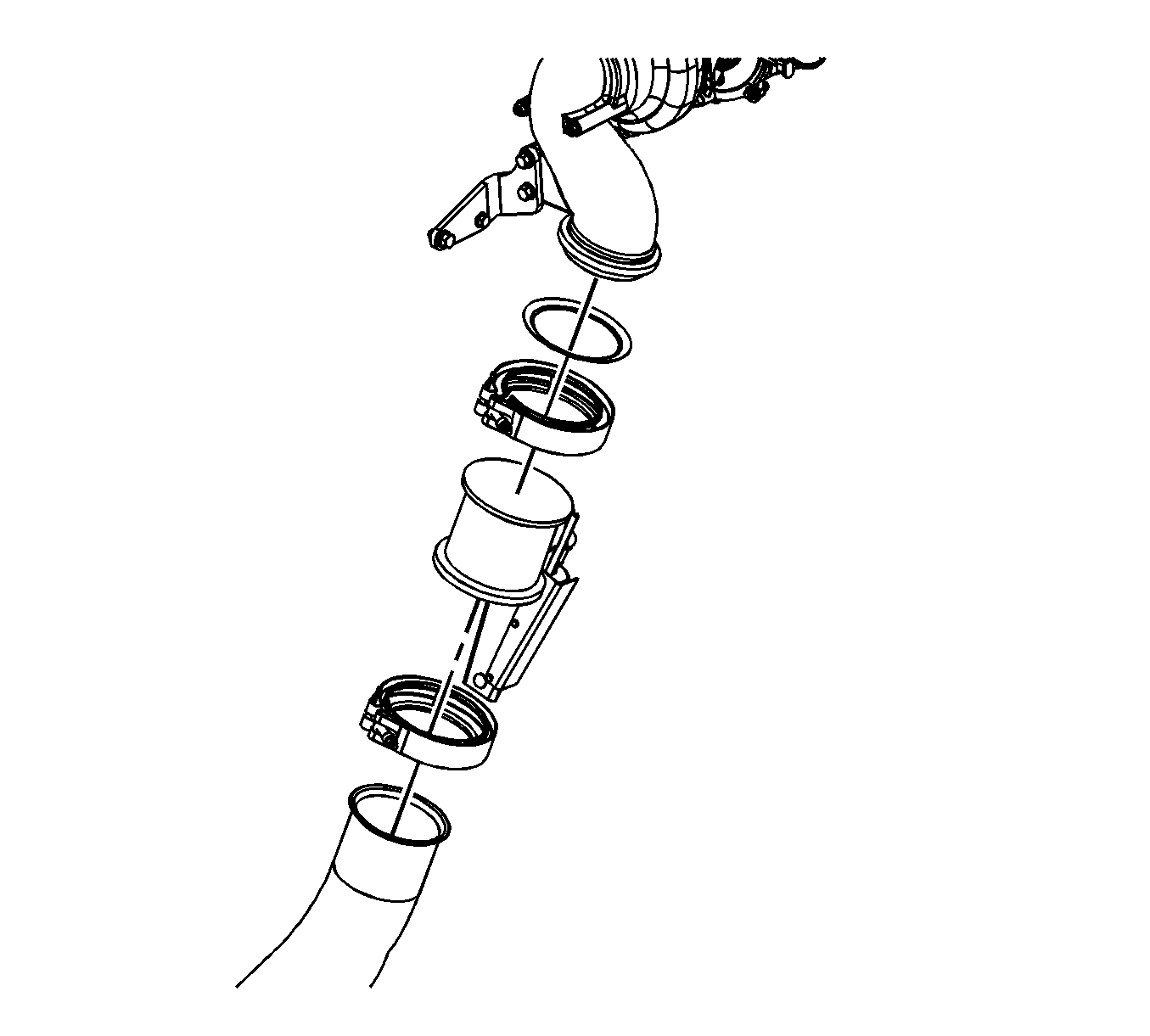
- Remove the exhaust pipe clamp and the exhaust pipe and seal from the exhaust pipe adapter.
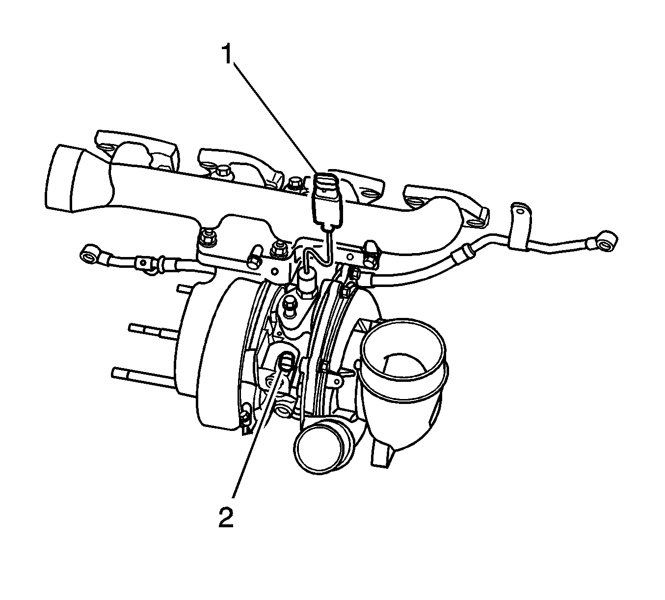
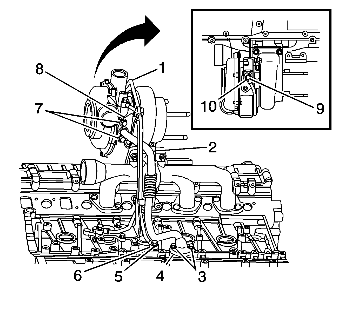
- Disconnect the turbocharger vane position sensor electrical connector (1).
- Disconnect the turbocharger vane position control solenoid electrical connector (2).
- Remove the air cleaner layer. Refer to Air Cleaner Assembly Replacement .
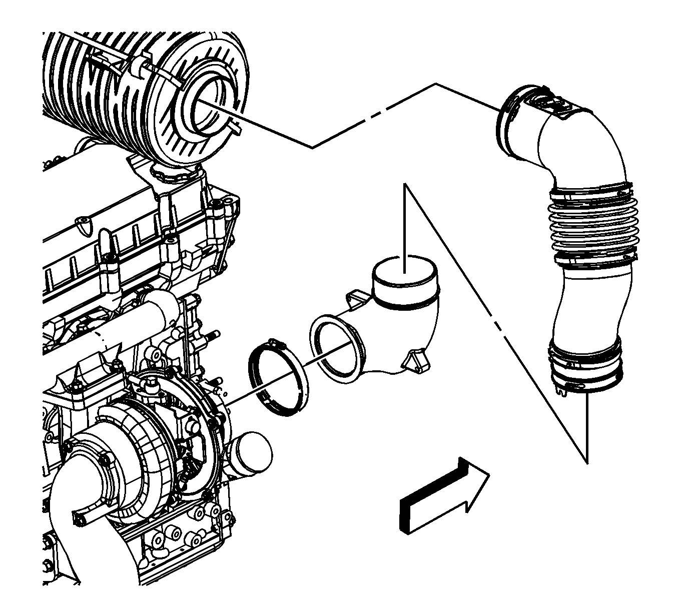
- Loosen the elbow clamp at the air cleaner assembly and the elbow clamp at the turbocharger and remove the duct assembly from the turbocharger and the air cleaner.
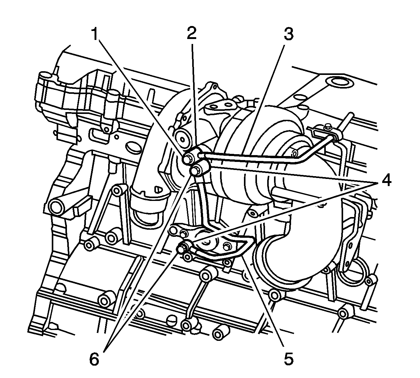
- Remove the coolant feed line eye bolt (6), washers (4) and the coolant feed line (5) from the turbocharger.
- Remove the coolant return line eye bolt (1), washer (2) and the coolant return line (3) from the turbocharger.
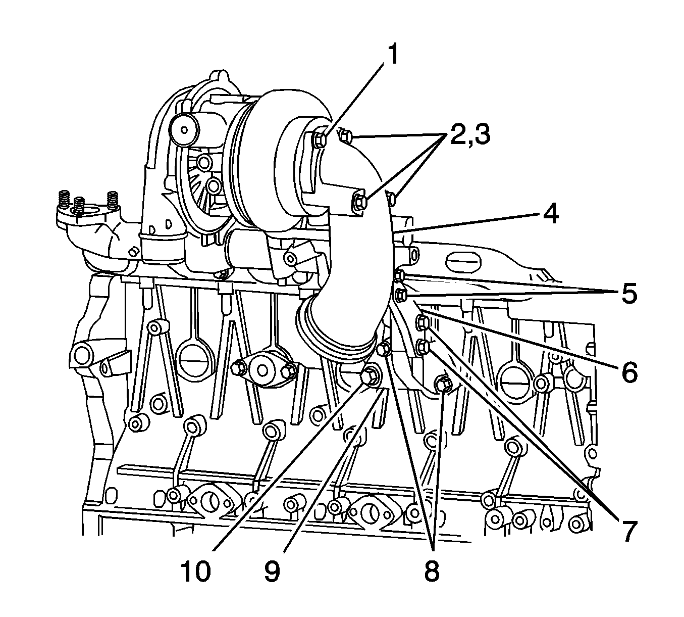
- Remove the oil feed pipe eye bolts (5, 9), gaskets (6, 10) and the oil feed pipe (1) from the engine block and the turbocharger.
- Remove the oil return tube bolts (3, 7) oil return tube (2) and gaskets (4, 8) from the turbocharger and the engine block.
- Remove the exhaust pipe adapter bracket bolts (5, 7, 8, 10) and the exhaust pipe adapter bracket (6, 9) from the exhaust pipe adapter (4) and the engine block.
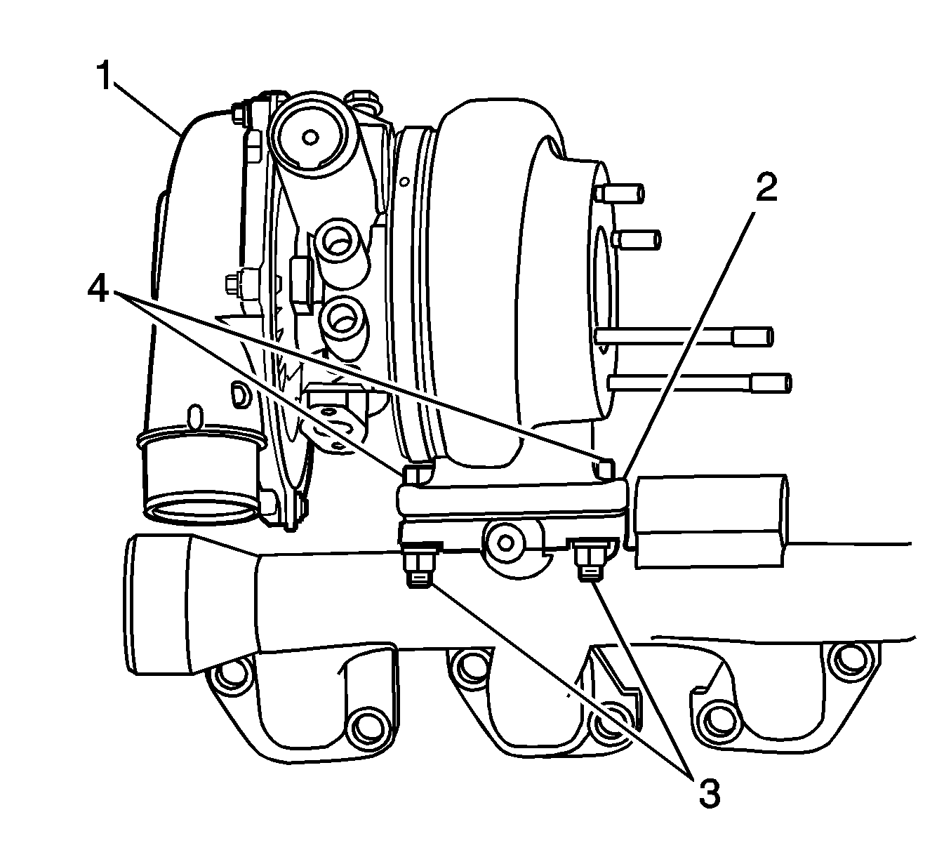
- Remove the exhaust pipe adapter nuts and washers (2, 3), the exhaust pipe adapter (4) and the exhaust pipe adapter gasket (1) from the turbocharger.
- Remove the turbocharger nuts and washers (3), bolts (4), turbocharger (1) and gasket (2) from the exhaust manifold.
Notice: If a turbocharger has failed, clean any turbocharger debris or excessive oil from the charge air cooler system before installing the new turbocharger. Failure to clean debris from the charge air cooler system will cause severe turbocharger and engine damage upon startup. Failure to clean excessive oil from the charge air cooler system may cause an engine runaway condition on startup, resulting in severe engine damage.
Bearing Radial Clearance Measurement Procedure
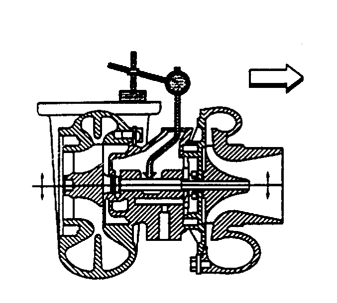
- Use a dial indicator with an offset plunger and magnetic base. Set the plunger so that the indicator touches the turbocharger main shaft.
- Set the dial indicator to 0.
- Hold the turbocharger shaft to prevent it from moving. Move the compressor and turbine wheel up and down. Read the shaft diametical play (compressor and turbine side clearance) on the dial indicator.
Specification
Compressor and Turbine Shaft Play: 0.108-0.140 mm (0.0043-0.0055 in)
Compressor End Play Measurement Procedure
- Use a dial indicator with an offset plunger and magnetic base. Set the plunger so that the indicator touches the turbocharger main shaft.
- Set the dial indicator to 0.
- Move the turbocharger shaft back and forth. Read the thrust end play (compressor clearance) on the dial indicator.
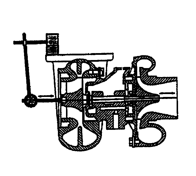
Specification
Thrust End Play: 0.045-0.090 mm (0.0018-0.0035 in)
Inspection Procedure
- Inspect the gasket mating surfaces of the turbocharger for cracks.
- Inspect the turbine blades for carbon residue and other damage.
- Use your hand to rotate the compressor wheel. The compressor wheel must turn smoothly and freely. There must be no binding or abnormal noise.
Installation Procedure
- Install the new gasket (2). The unmarked side of the gasket must be facing the exhaust manifold.
- Install the turbocharger (1) to the exhaust manifold.
- Install the oil drain tube (2) and gaskets (4, 8) to the turbocharger and cylinder block with bolts (3, 7).
- Install the washers and nuts (3) to the exhaust manifold bolts (4).
- Install the oil feed pipe (1) and new gaskets (6) to the turbocharger and cylinder block with eye bolts (5, 9).
- Install the oil feed pipe clamp and bolt.
- Install the new gasket (1) to the exhaust pipe adapter (4).
- Connect the exhaust pipe adapter (4) to the turbocharger.
- Install the exhaust pipe adapter nuts and washers (2, 3) to the turbocharger.
- Install the exhaust pipe adapter bracket (6, 9) to the cylinder block with bolts (5, 7, 8, 10).
- Install the exhaust pipe adapter bracket (6) to the exhaust pipe adapter (4) with bolts (5, 7).
- Install the water pipes (1, 4) to the turbocharger with 2 new gaskets (2, 5) and eye bolts (3, 6).
- Connect the turbocharger vane position sensor electrical connector (1).
- Connect the turbocharger vane position control solenoid electrical connector (2).
- Install the exhaust pipe to the exhaust pipe adapter with seal and clamp.
- Install the air cleaner duct assembly to the turbocharger with clamp.
- Connect the air inlet hose to the turbocharger and the charge air cooler.
- Install the air cleaner layer. Refer to Air Cleaner Assembly Replacement .
- Connect the negative battery cable at the battery. Refer to Battery Negative Cable Disconnection and Connection .

Notice: Refer to Fastener Notice in the Preface section.

Tighten
Tighten the bolts (3, 7) to 25 N·m (18 lb ft).

Tighten
Tighten the nuts (3) to 52 N·m (38 lb ft).

Important: Pour 118.3 ml (4 ounces) of clean engine oil into the oil feed port to pre-lubricate the turbocharger. Turn the compressor wheel with your hand to distribute the oil.
Tighten
| • | Tighten the bolt (9) to 34 N·m (25 lb ft). |
| • | Tighten the bolt (5) to 41 N·m (30 lb ft). |

Tighten
Tighten the nuts to 26 N·m (19 lb ft).
Tighten
Tighten the bolts (8, 10) to 24 N·m (18 lb ft).
Tighten
Tighten the bolts (5, 7) to 50 N·m (37 lb ft).
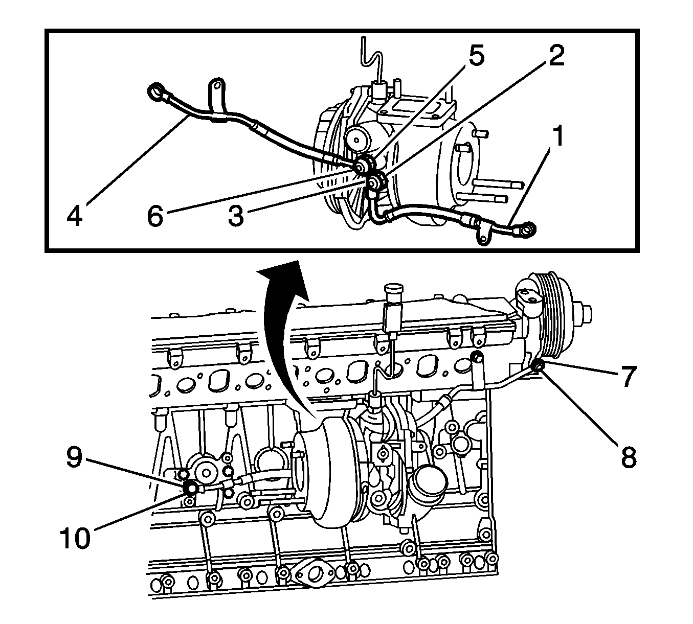
Tighten
Tighten the bolts (3, 6) to 41 N·m (30 lb ft).


