Charge Air Cooler Diagnosis Charge Air Cooler Air Leak Test
Diagnostic Instructions
| • | Perform the Diagnostic System Check - Vehicle prior to using this diagnostic procedure. |
| • | Review Strategy Based Diagnosis for an overview of the diagnostic approach. |
| • | Diagnostic Procedure Instructions provide an overview of each diagnostic category. |
Special Tools
| • | EN-47603 Compression Gage Adapter |
| • | J 46091 Charge Air Cooler Tester |
| • | J-46091-10 Charge Air Cooler Tester Adapter |
J 46091-1 Pressure Regulator Adjustment
Important: Some J 46091-1 regulators may have the adjusting knob riveted in place. The rivet head must be drilled out with a 5/16 inch drill bit before adjustment. Do not drill more than 1/8 inch in depth, or just enough to remove the rivet head. The rivet shaft does not have to be removed from the regulator.
- Connect the EN-47603 compression adapter to the J 46091 gage set and connect shop air to the J 46091 .
- Open the shutoff valve, then slowly turn the regulator on the J 46091 clockwise until the gage reads 206 kPa (30 psi).
- Close the air supply valve and remove the EN-47603 from the gage assembly.
- The gage set is now calibrated to perform the test.
Charge Air Cooler Outlet Connection (Engine Air Intake COLD Side)
Important: It is not necessary to remove the charge air cooler from the vehicle to perform this test.
- Remove both wheelhouse panels. Refer to Wheelhouse Panel Replacement .
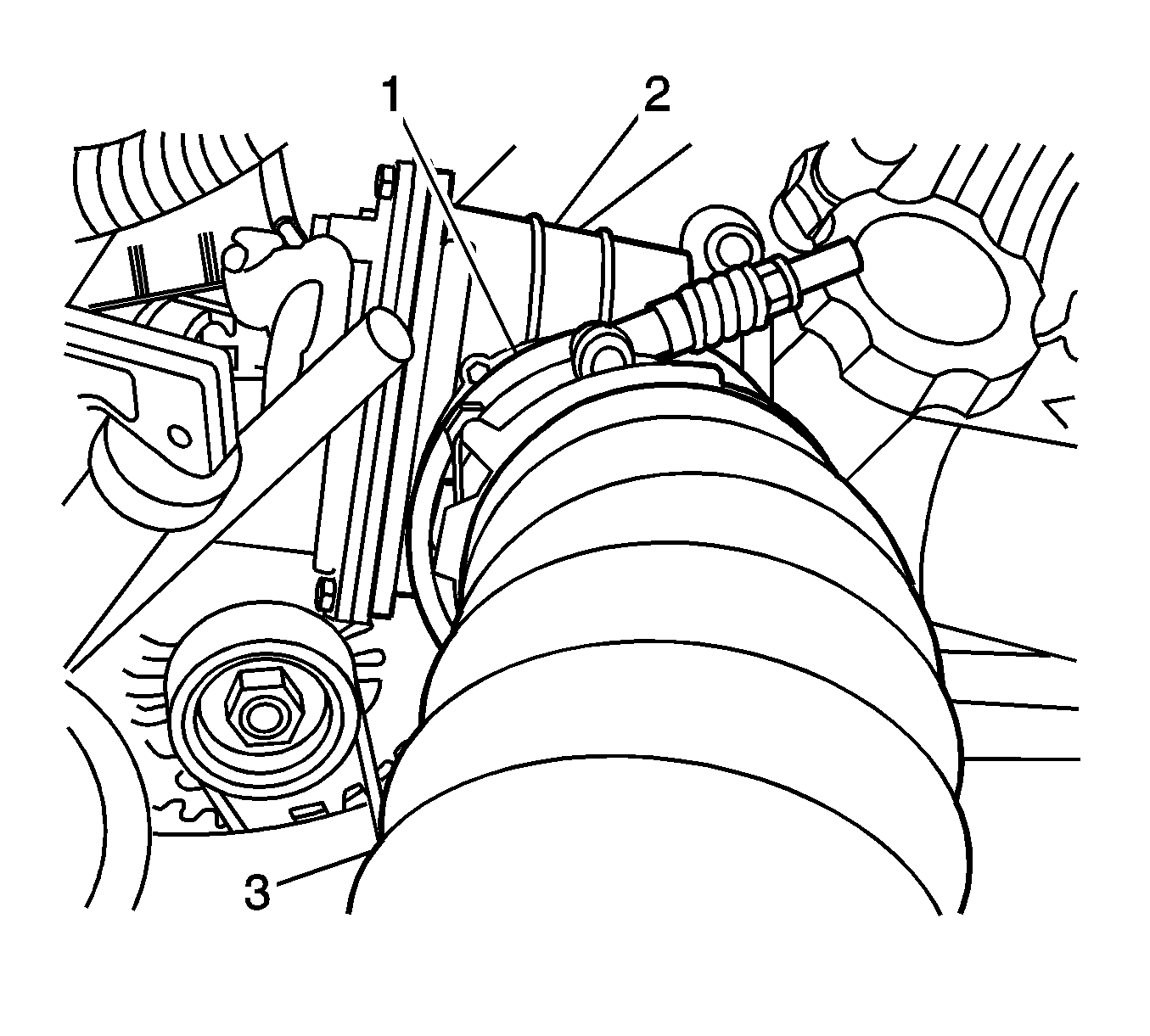
- Loosen the charge air cooler (CAC) clamp (1) that fastens the right air cooler duct to the intake air valve (2).
- Remove the right charge air cooler duct (3) from the intake air valve inlet.
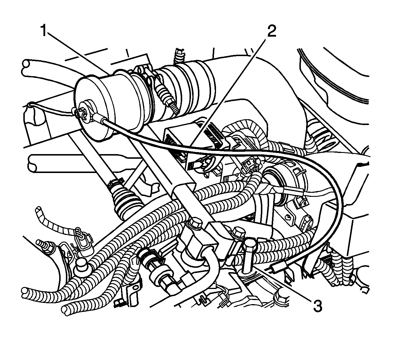
- Install the J-46091-10 adapter to the charge air duct.
- Use the clamp to secure the adapter to the charge air duct.
- Secure the safety cable.

Important: After removing the charge air cooler duct, protect the intake air valve opening in order to prevent entry of objects.
Notice: Refer to Fastener Notice in the Preface section.
Tighten
Tighten the clamp to 8 N·m (70 lb in).
Caution: To prevent possible injury from the coupler blowing off the charge air cooler hose during the test, connect the safety cable before applying air pressure.

Charge Air Cooler Inlet Connection (Engine Air Intake HOT Side)

- Remove the engine cover. Refer to Engine Cover Replacement .
- Remove the air cleaner. Refer to Air Cleaner Assembly Replacement .
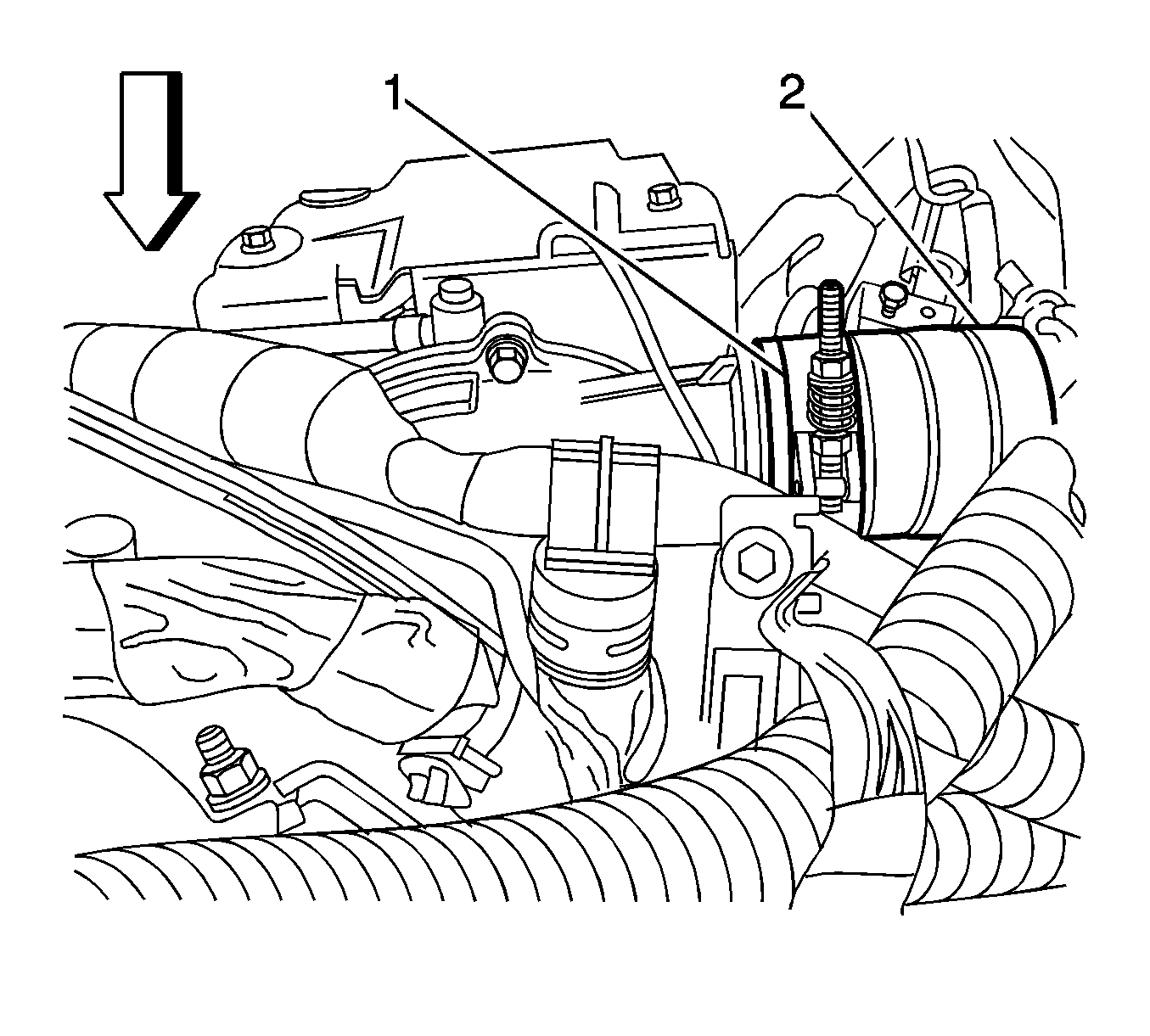
- Loosen the right clamp that fastens the left air cooler duct to turbocharger (1).
- Remove the left charge air cooler inlet duct connector (2) from the turbocharger.
- Use the clamp to attach the gage couple from the J 46091 adapter to the charge air hose.
- Secure the safety cable.
- Attach the gage/regulator assembly from the J 46091 to the quick disconnect fitting on the gage coupler.
Important: After removing the air cleaner assembly, protect the engine opening to prevent entry of objects.
Important:
• After removing the charged air cooler duct, cover the turbocharger to prevent entry of objects. • Do not use a screwdriver or other tool to pry the hose loose. The hose can be torn or damaged. Loosen the hose by twisting.
Tighten
Torque the clamp to 8 N·m (70 lb in).
Caution: Refer to Charge Air Cooler Caution in the Preface section.
Leak Test - Air Pressure Application
Caution: Refer to Charge Air Cooler Caution in the Preface section.
Important: Charge air coolers are not required to be leak proof. Do not test the cooler for leakage by submerging it in a radiator test tank. Almost all charge air cooler units will show leakage if they are submerged.
- Connect the filtered air supply to the air valve on the gage/regulator assembly.
- Open the air valve slowly, increasing the air pressure in 34-69 kPa (5-10 psi) increments while listening for air leaks. Continue increasing the air pressure until the gage reads 205 kPa (30 psi).
- Close the air valve and monitor the gage for 15 seconds. Note any decrease in air pressure.
- Repeat the test 3 times to verify the results.
Leak Test Fails
If the pressure drop is greater than 34 kPa (5 psi) in 15 seconds, the leak test has failed. Perform the following procedure:
- Inspect for air leaks using a pump spray bottle to apply a soapy solution to the pipes/hoses, charge air cooler hose connections, and charge air cooler core. Observe for bubbles.
- Replace or tighten the affected component as necessary.
- Retest the CAC system. If no other leaks are found, assemble the vehicle and clear the DTC information with a scan tool.
- Perform a Service Regeneration with a scan tool. Refer to Diesel Particulate Filter (DPF) Service Regeneration .
Notice: After performing the system repair, perform the following:
• A code clear with a scan tool, regardless of whether or not a DTC is set • A Diesel Particulate Filter (DPF) Service Regeneration with a scan tool
Leak Test Passes
If the pressure drop is less than 34 kPa (5 psi) in 15 seconds, the leak test passes. Remove the tester by performing the following procedure:
- Slowly bleed the air from the cooler by depressing the relief valve on the adapter plate.
- Remove the air hose, gage/regulator assembly, and both adapters.
- Connect the charge air hose to the turbocharger.
- Install the engine cover. Refer to Engine Cover Replacement .
- Install the air cleaner assembly. Refer to Air Cleaner Assembly Replacement .
- Install both wheelhouse panels. Refer to Wheelhouse Panel Replacement .
Tighten
Torque the clamp to 8 N·m (70 lb in).
