Relay Rod Replacement 4WD
Tools Required
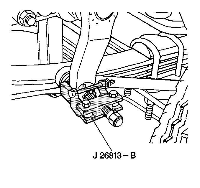
J 26813-B Steering Linkage Puller
Removal Procedure
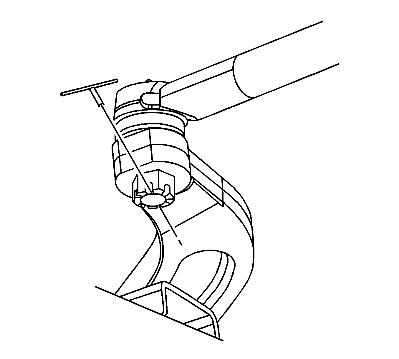
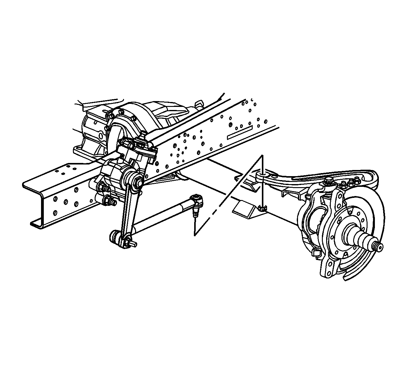
- Remove the relay rod to steering arm cotter pin and discard.
- Remove the relay rod to steering arm nut.
- Using J 26813-B , remove the relay rod from the steering arm.
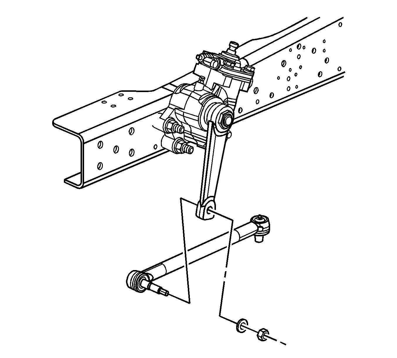
- Remove the relay rod to pitman arm nut and washer.
- Using J 26813-B , remove the relay rod from the pitman arm.
- Inspect the relay rod (11) for damage.
- Inspect the end assembly stud threads for damage.
- Inspect the assembly rubber seals for the following conditions:
- Install the relay rod nuts.
- Use a torque wrench in order to measure the torque used to turn the ball stud.
- Replace the relay rod if the turning torque is less than 0.5 N·m (5 lb in).
Important: Before removing the relay rod mark, position so it can be referenced on installation.
| • | Damage |
| • | Deterioration |
Installation Procedure
- Install the relay to the pitman arm.
- Install the relay rod to pitman arm washer and nut.
- Install the relay rod to the steering arm.
- Install the relay rod to the steering arm nut.
- Advance the relay rod nut to the nearest cotter pin slot.
- Install the new cotter pin.
- Lubricate the relay rod with chassis lubricant. Refer to Fluid and Lubricant Recommendations and Maintenance Schedule .
Important: Note the position of the relay rod from removal process so the relay rod is not installed backwards.

Notice: Refer to Fastener Notice in the Preface section.
Tighten
Tighten the nut to 210 N·m (155 lb ft).

Tighten
Tighten the nut to 129 N·m (96 lb ft).

Important: Do not back off a relay rod nut in order to insert a cotter pin.
Relay Rod Replacement 2WD
Tools Required
J 26813-B Steering Linkage Puller
Removal Procedure
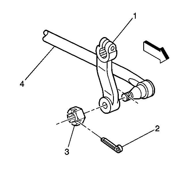
A non-adjustable relay rod connects the pitman arm to the steering arm. If the relay rod becomes worn or damaged, replace the complete assembly.
- Remove the cotter pin (2).
- Discard the cotter pin.
- Remove the relay rod nut (3).
- Use the J 26813-B in order to remove the relay rod from the pitman arm.
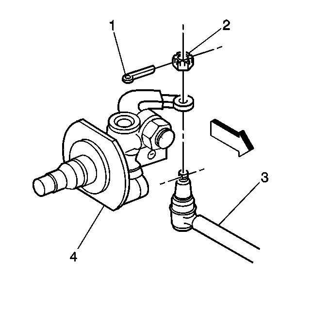
- Remove the cotter pin (1) and discard.
- Remove the nut (2) from the steering arm.
- Use the J 26813-B in order to remove the relay rod (3) from the steering arm.
- Remove the relay rod (3).
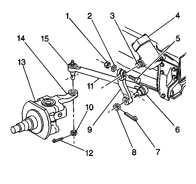
- Inspect the relay rod (11) for damage.
- Inspect the end assembly stud threads for damage.
- Inspect the assembly rubber seals for the following conditions:
- Install the relay rod nuts (8, 10).
- Use a torque wrench in order to measure the torque used to turn the ball stud.
- Replace the relay rod if the turning torque is less than 0.5 N·m (5 lb in).
Important: In some applications a lock style nut may be used. If a lock style nut is used it should be discarded and replaced with a new lock style nut.

Important: Before removing relay rod mark its position so it can be referenced on installation.
Important: In some applications a lock style nut may be used. If a lock style nut is used it should be discarded and replaced with a new lock style nut.
| • | Damage |
| • | Deterioration |
Installation Procedure
- Install the relay rod (4) ball joint-pitman arm end to the pitman arm (1).
- Install the relay rod to pitman arm nut.
- Install the relay rod (3) ball joint steering arm end to the steering arm.
- Install the steering arm/relay rod nut.
- Advance both relay rod nuts (8, 10) to the nearest cotter pin slot.
- Install the new cotter pins (7, 12) if a lock style nut was not used.
- Lubricate the relay rod with chassis lubricant. Refer to Fluid and Lubricant Recommendations and Maintenance Schedule .

Important: Note position of relay rod from removal process so the relay rod is not installed backwards.
Notice: Refer to Fastener Notice in the Preface section.
Tighten
| • | FN9/FM7 - Tighten the relay rod nut to 210 N·m (155 lb ft). |
| • | FM8 - Tighten the relay rod nut to 129 N·m (96 lb ft). |
| • | FM6/FS7/FL3/FH4 - Tighten the relay rod nut to 162 N·m (120 lb ft). |

Tighten
| • | FN9/FM7/FM8 - Tighten the steering arm/relay rod nut to 210 N·m (155 lb ft). |
| • | FM6/FS7/FL3/FH4 - Tighten the steering arm/relay rod nut to 325 N·m (239 lb ft). |

Important: Do not back off a relay rod nut in order to insert a cotter pin.
