Caution: If a turbocharger has failed, clean any turbocharger debris or excessive oil from the charge air cooler system before installing the new turbocharger. Failure to clean debris from the charge air cooler system will cause severe turbocharger and engine damage upon startup. Failure to clean excessive oil from the charge air cooler system may cause an engine runaway condition on startup, resulting in severe engine damage.
Note: If a turbocharger failure is thought to be caused due to a lack of oil, the camshaft bearing should be checked. The number 4 camshaft bearing bore feeds the turbocharger oil supply (feed) pipe. If this camshaft bearing spins in the bore, the turbocharger will be starved for oil. This will cause a failure of the turbocharger. Failure to diagnosis this condition will result in repeat turbocharger failures.
- Disconnect the negative battery cable. Refer to Lifting and Jacking the Vehicle.
- Remove the left exhaust pipe. Refer to Exhaust Pipe Replacement - Left Side.
- Remove the right exhaust pipe. Refer to Exhaust Pipe Replacement - Right Side.
- Remove the exhaust gas recirculation (EGR) cooler tube. Refer to Exhaust Gas Recirculation Valve Cooler Replacement.
- Remove the charge air cooler outlet pipe. Refer to Charge Air Cooler Inlet Pipe and Outlet Pipe Replacement.
- Remove the air intake pipe. Refer to Air Intake Pipe Replacement.
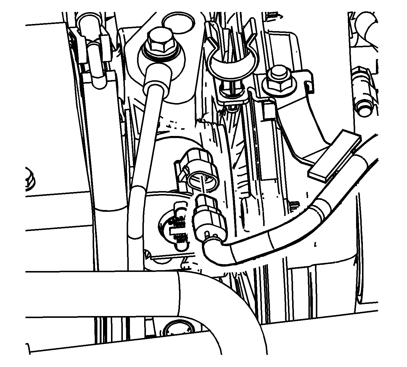
- Disconnect the engine wiring harness electrical connector from the turbocharger vane position sensor.
- Disconnect the engine wiring harness electrical connector from the turbocharger vane control solenoid valve.
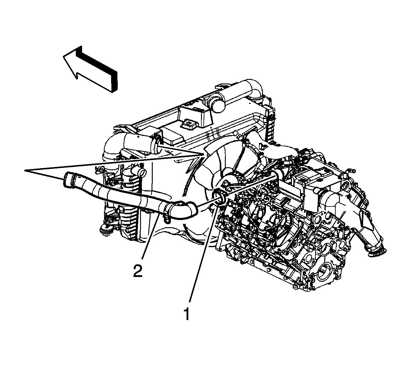
- Loosen the charge air cooler inlet duct clamp (1) at the turbocharger.
- Remove the charge air cooler inlet duct (2) from the turbocharger
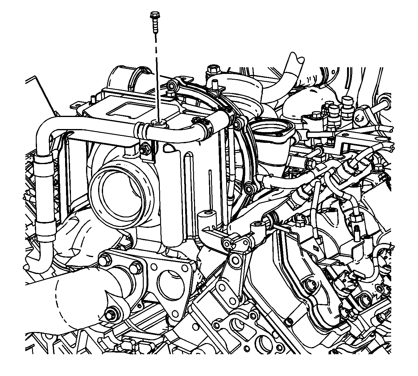
- Remove the EGR cooler pipe bolt.
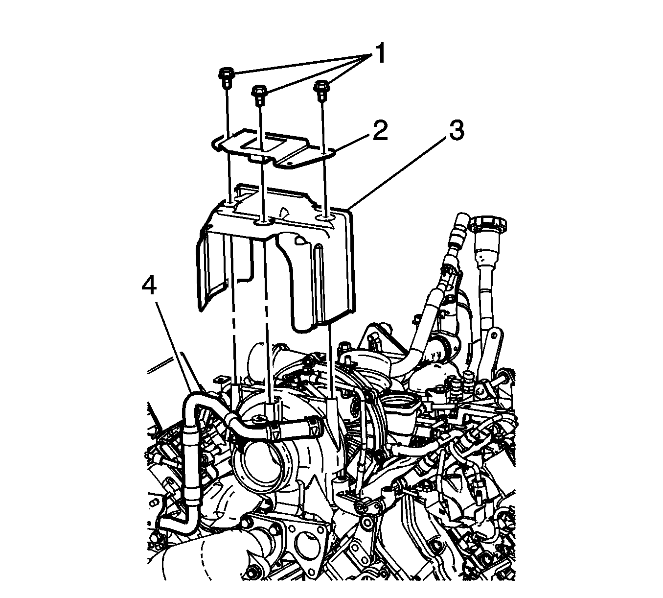
- Reposition the EGR cooler pipe (4) out of the way.
- Remove the EGR valve adapter pipe bracket bolts (1).
- Remove the EGR valve adapter pipe bracket (2) and turbocharger heat shield (3).
- Reposition the turbocharger coolant outlet pipe clamp (1) and remove the hose from the turbocharger pipe.
- Reposition the turbocharger coolant inlet pipe clamp (1) and remove the hose from the turbocharger pipe.
- Remove the turbocharger oil feed pipe banjo bolt and washer. Discard the banjo bolt and washer.
- Reposition and secure the turbocharger oil feed pipe out of the way.
- Remove the turbocharger oil return pipe nuts at the top of the flywheel housing.
- Remove the turbocharger bolts.
- Remove the turbocharger (with the oil return pipe).
- Remove and discard the turbocharger oil return pipe gasket at the flywheel housing.
- Remove the turbocharger lower heat shield, if necessary.
- Remove the turbocharger oil feed pipe bolt, washer, and pipe, if necessary.
- If the turbocharger has failed, perform the following steps in order to verify the condition of the number 4 camshaft bearing before installing a new turbocharger.
- If replacing the turbocharger perform the following steps otherwise proceed to step 11 in the installation procedure.
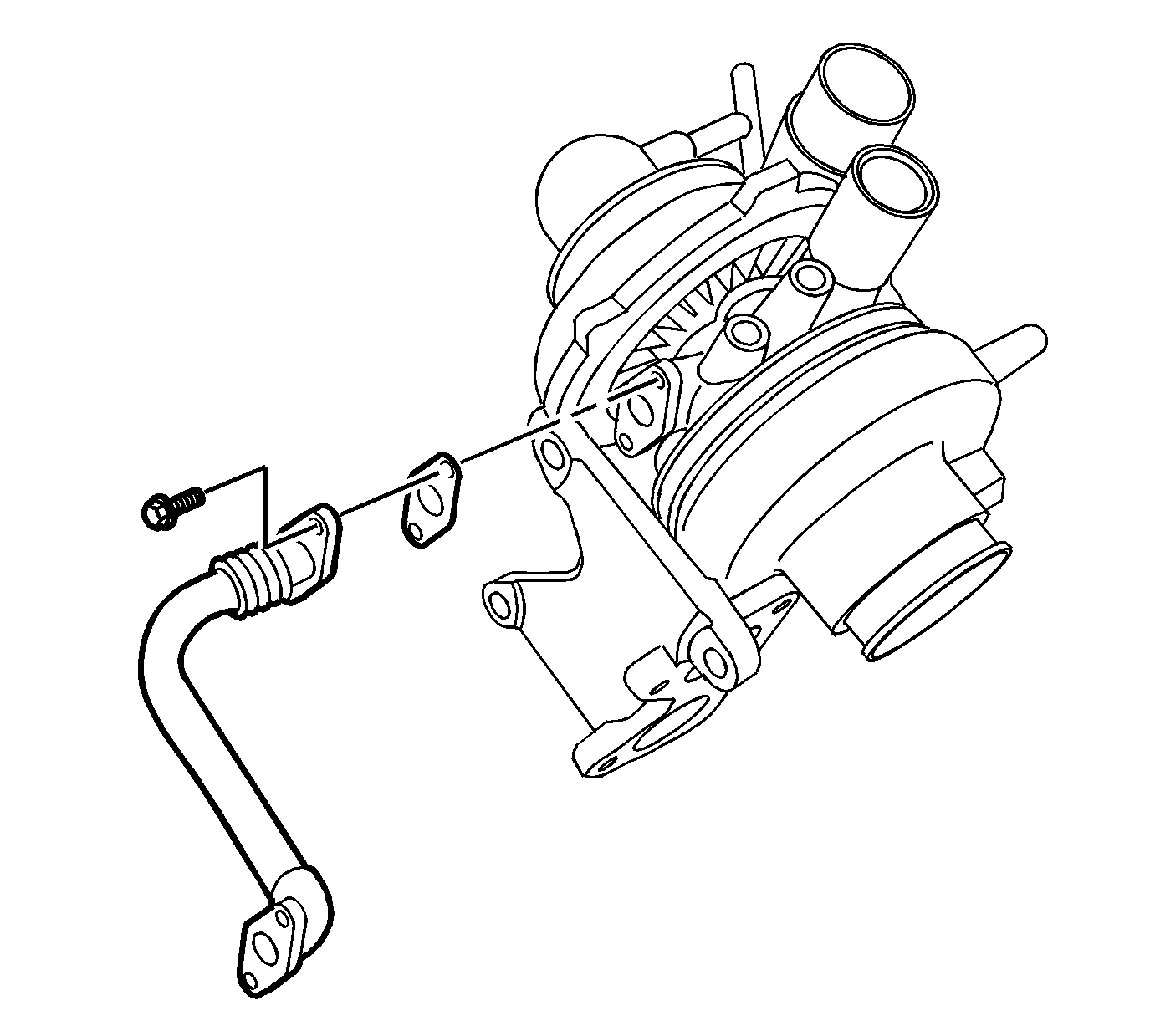
- Remove the oil return pipe bolts, pipe, and gasket from the turbocharger. Discard the gasket.
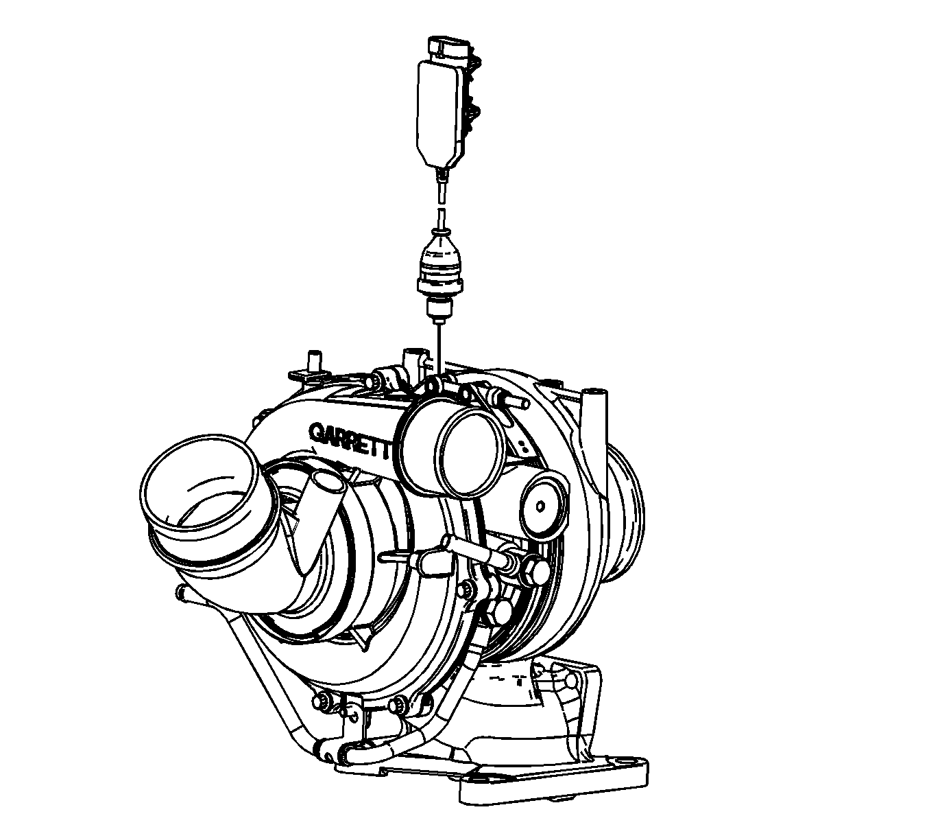
- Remove the turbocharger vane position sensor.
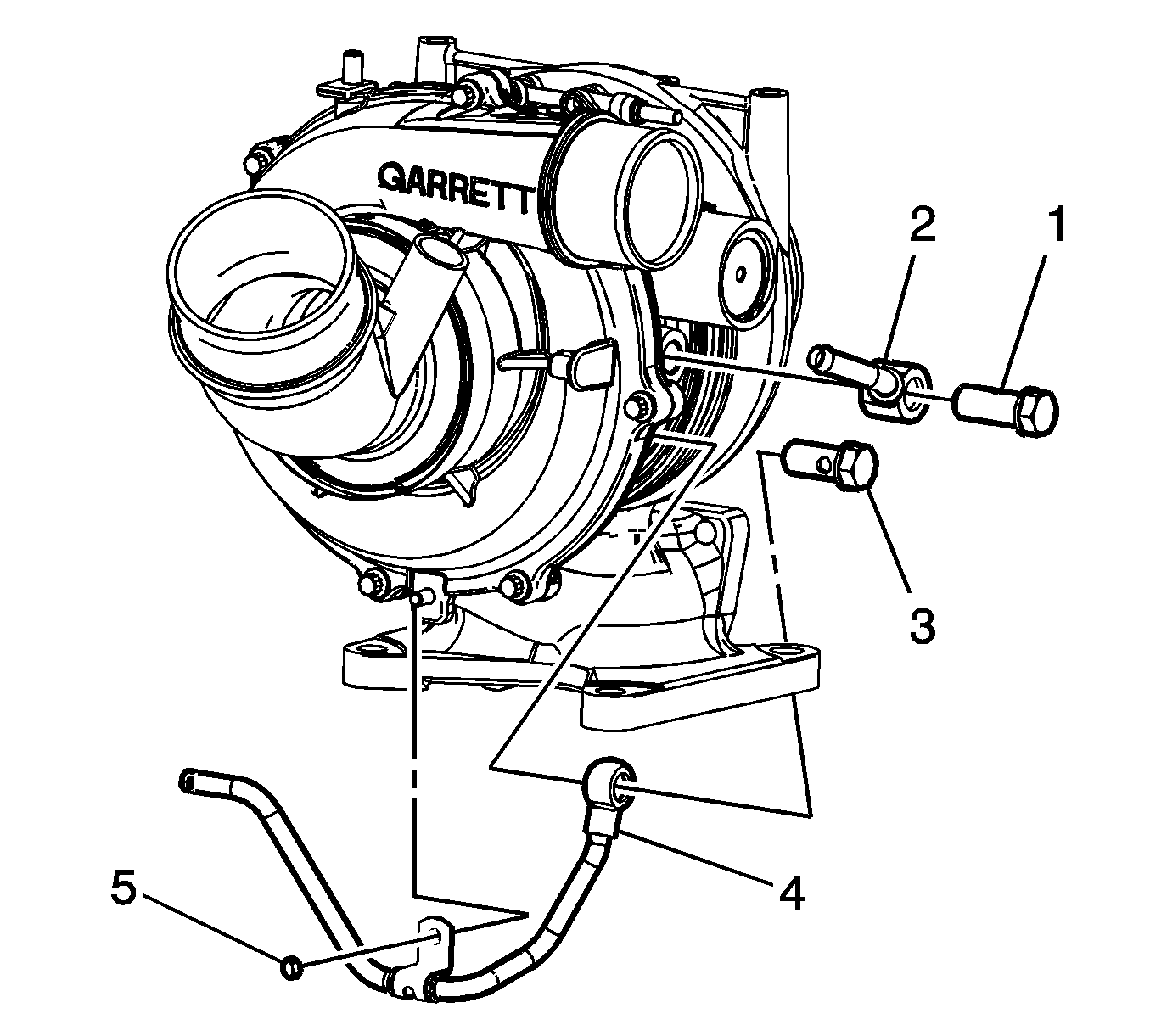
- Remove the turbocharger coolant feed pipe banjo bolt (1), washers and pipe (2).
- Remove the turbocharger coolant return pipe banjo bolt (3) and washers.
- Remove the turbocharger coolant return pipe clip nut (5) and pipe (4).
Note:
• Do not use a screwdriver or other tool to pry the hose loose. The hose can be torn or damaged. Loosen the hose by twisting. • After removing the charge air cooler duct, cover the turbocharger opening with tape in order to prevent entry of objects.
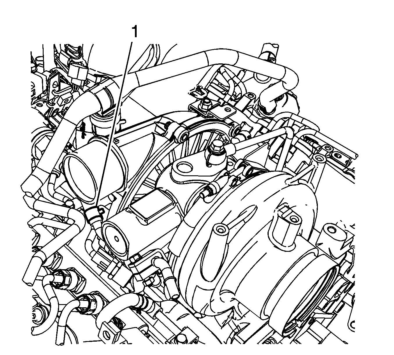
Note: Use care not to damage this hose during the procedure.
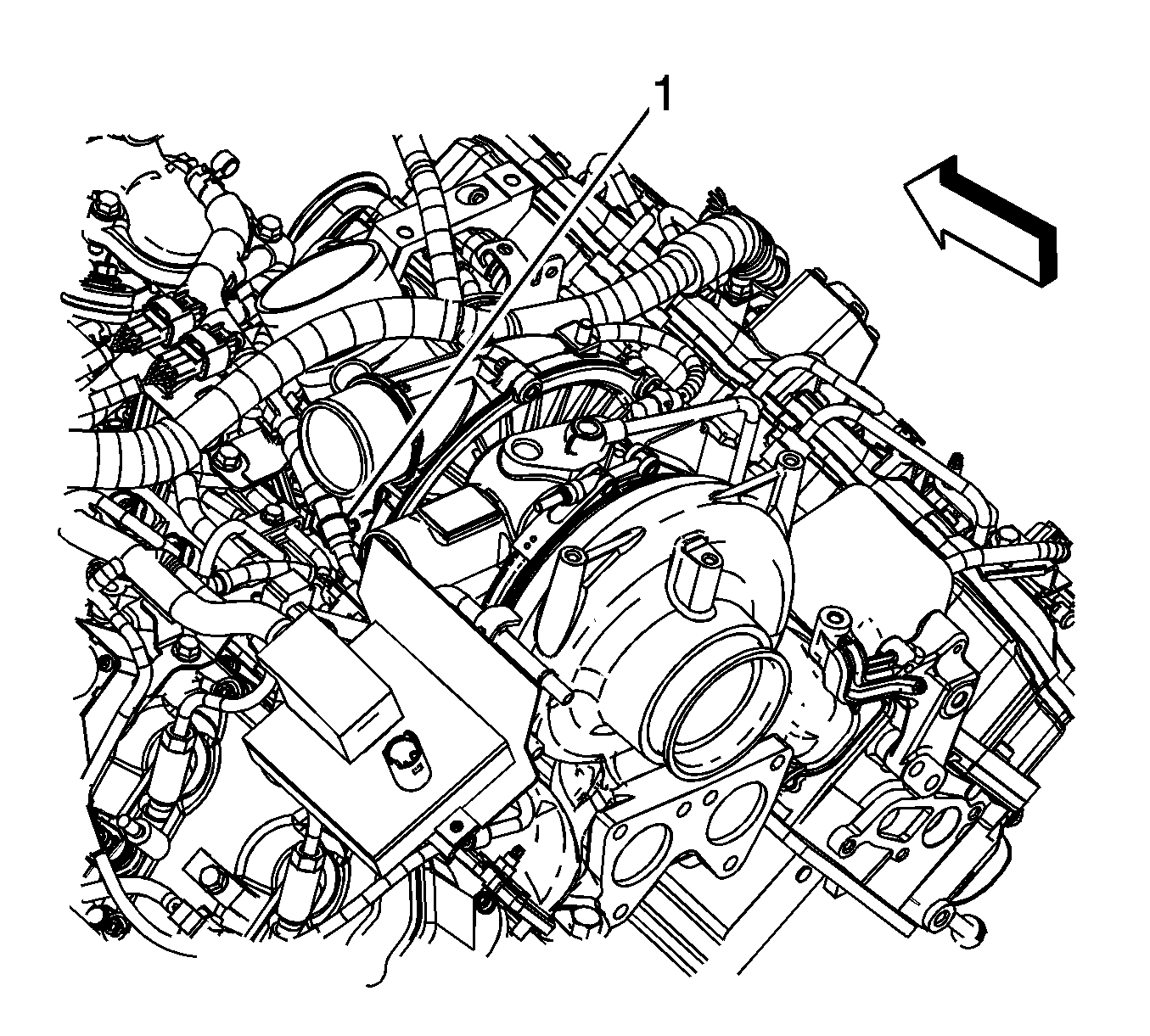
Note: Use care not to damage this hose during the procedure.
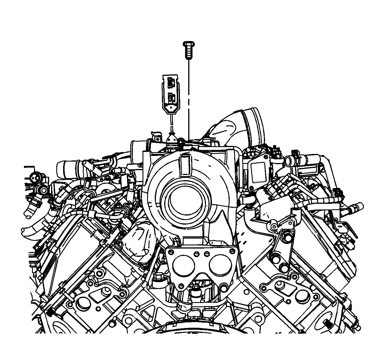
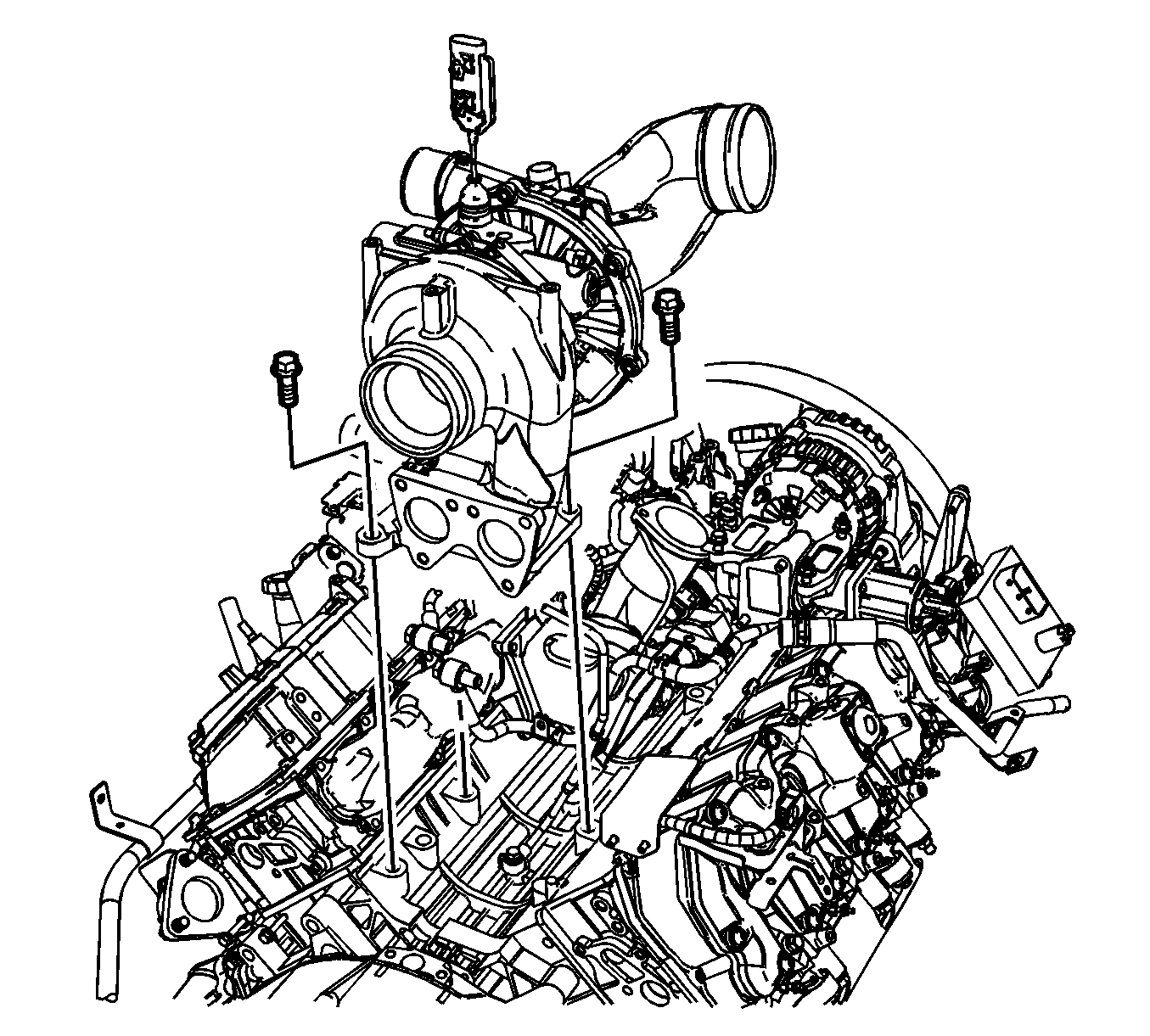
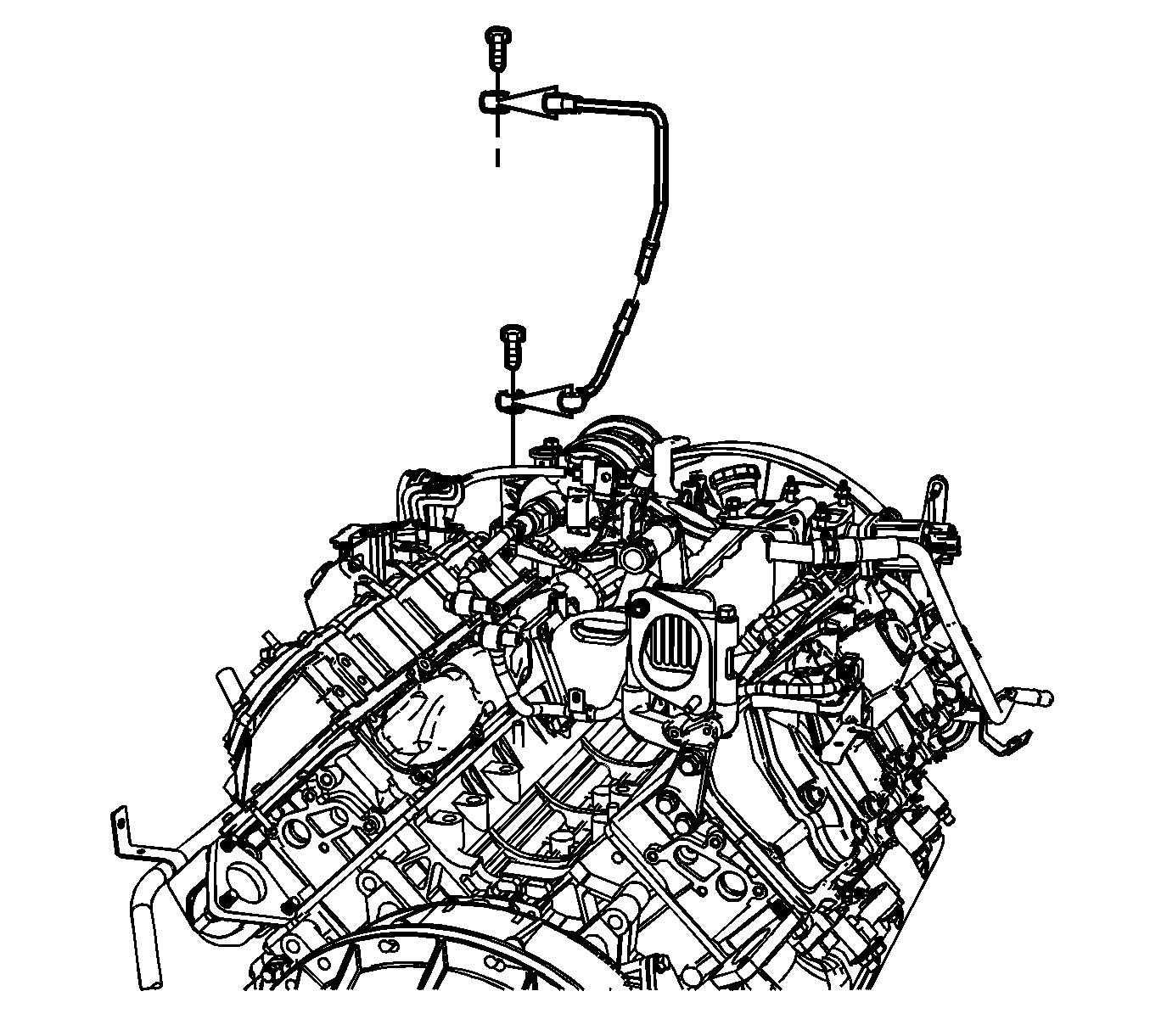
Caution: Do not twist the turbocharger oil feed pipe. Twisting of the feed pipe will result in the collapse and deformation of the plastic pipe, restricting oil flow and causing turbocharger damage. During turbocharger replacement, gently push the oil feed pipe towards the front of the engine to clear the turbocharger. Assistance may be required to keep the pipes clear of the turbocharger during removal or installation.
| • | Visually inspect for correct alignment of the number 4 camshaft bearing oil hole through the turbocharger oil supply hole in the block. |
| • | Turn the engine over by hand 1/2 turn and inspect for camshaft bearing movement, indicating a spun camshaft bearing. |
| • | If the bearing is spun the engine MUST be replaced. |
Installation Procedure
- If replacing the turbocharger perform the following steps otherwise proceed to step 11.
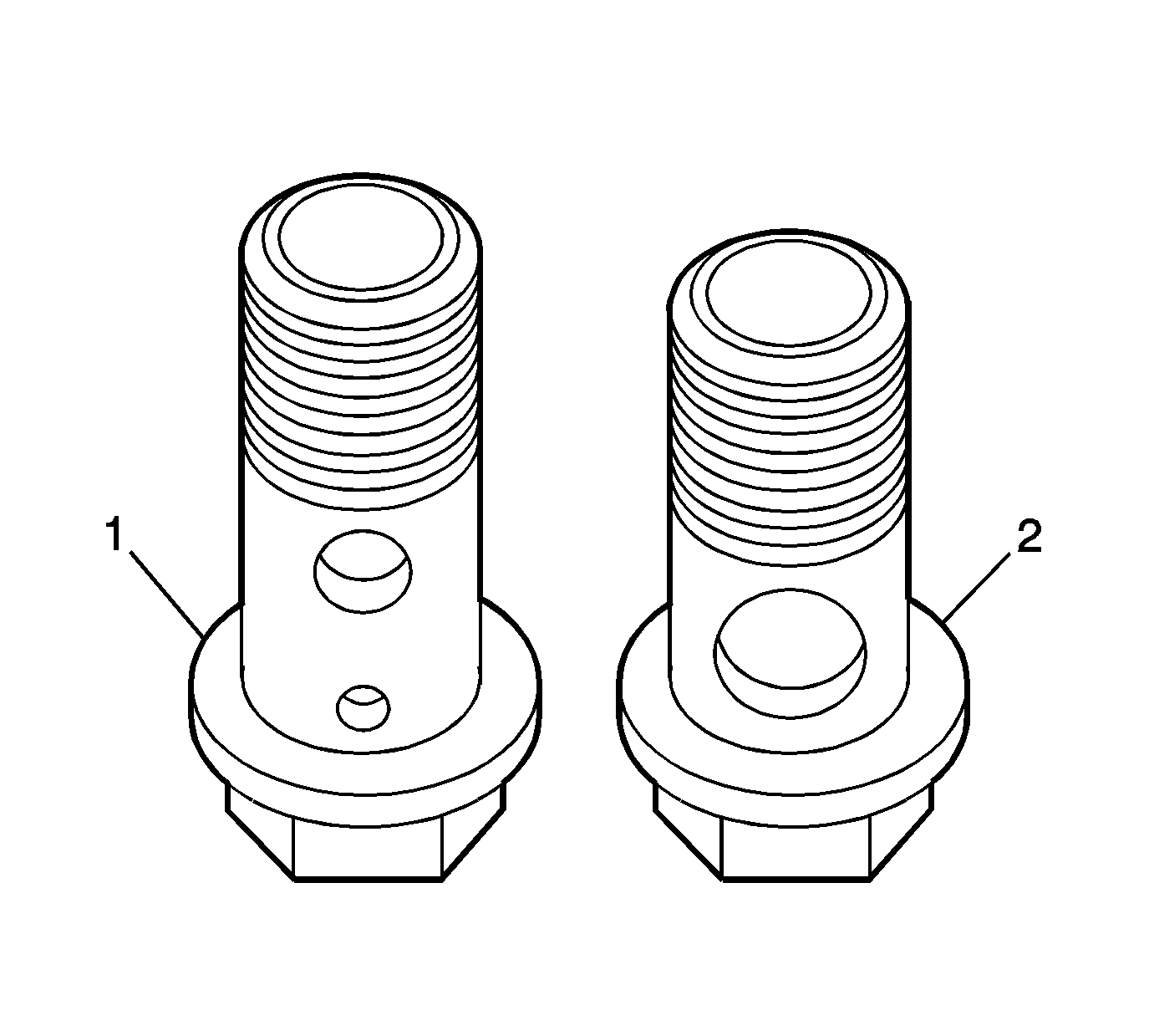
- Install the long bolt (1) with the 2 holes to the coolant inlet pipe and the short bolt (2) with one hole for the coolant outlet pipe.
- Position the turbocharger coolant return pipe (4) and install the clip nut (5).
- Position the turbocharger coolant return pipe washers and install the banjo bolt (3).
- Position the turbocharger coolant feed pipe washers and pipe (2), and install the banjo bolt (1).
- Install the turbocharger vane position sensor.
- Position a NEW oil return pipe gasket to the turbocharger and install the oil return pipe and bolts to the turbocharger.
- Install a NEW turbocharger oil feed pipe washer onto the banjo fitting, if necessary.
- Install the turbocharger oil feed pipe and bolt, if necessary.
- Install the turbocharger lower heat shield, if necessary.
- Install a NEW turbocharger oil return pipe gasket at the flywheel housing.
- Install the turbocharger.
- Install the turbocharger bolts.
- Install the turbocharger oil return pipe nuts at the top of the flywheel housing.
- Unsecure and position the turbocharger oil feed pipe to the correct position.
- Install a NEW turbocharger oil feed pipe washer onto the banjo fitting and install the feed pipe bolt.
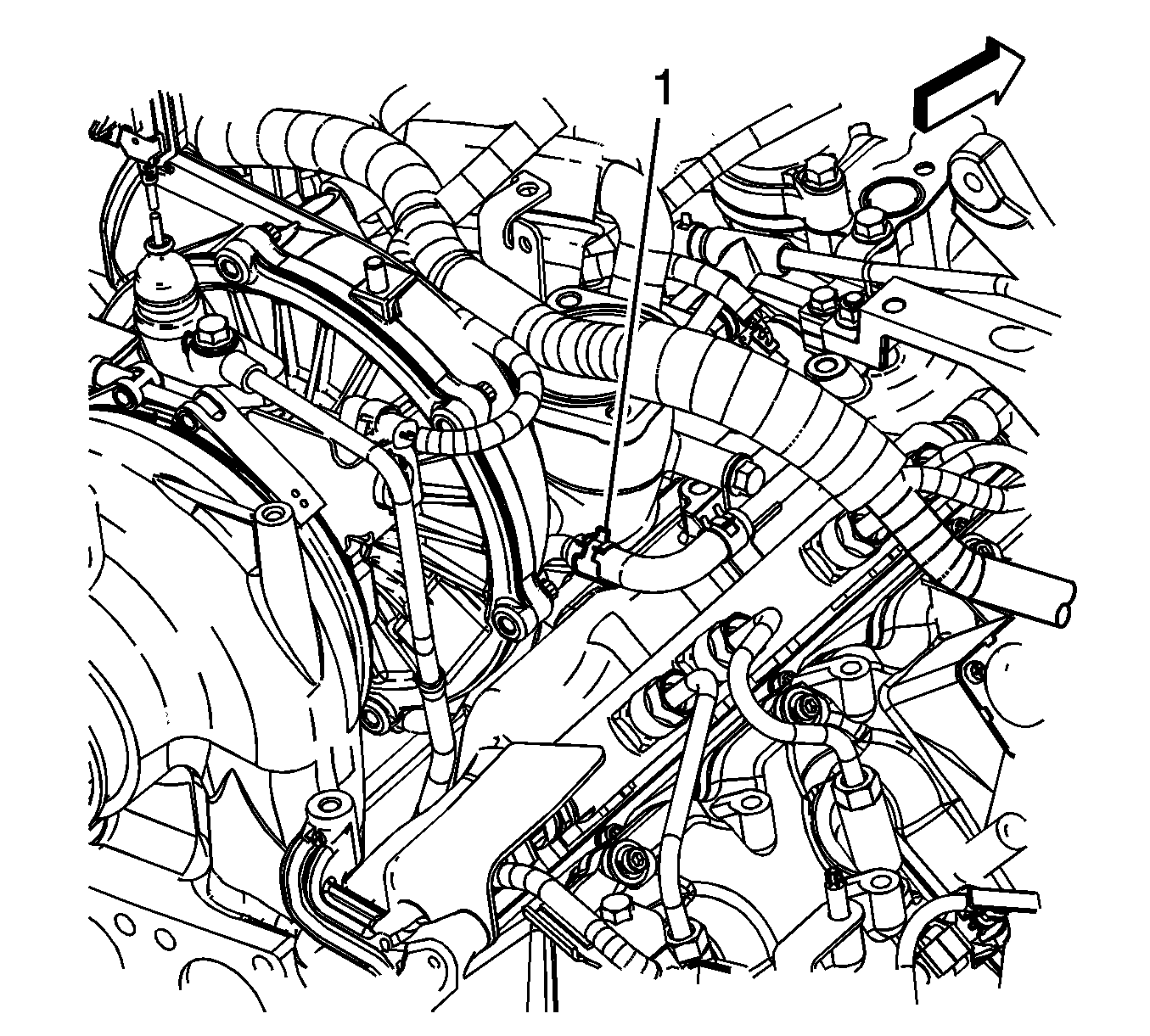
- Install the turbocharger coolant inlet pipe hose to the turbocharger pipe and position the clamp (1).
- Install the turbocharger coolant outlet hose to the turbocharger pipe and position the clamp (1).
- Install the turbocharger heat shield (3) and EGR valve adapter pipe bracket (2).
- Install the EGR valve adapter pipe bracket bolts (1).
- Position the EGR cooler pipe (4).
- Install the EGR cooler pipe bolt.
- Remove the tape from the turbocharger openings.
- Install the charge air cooler inlet duct (2) to the turbocharger
- Tighten the charge air cooler inlet duct clamp (1) at the turbocharger.
- Connect the engine wiring harness electrical connector to the turbocharger vane control solenoid valve.
- Connect the engine wiring harness electrical connector from the turbocharger vane position sensor.
- Install the air intake pipe. Refer to Air Intake Pipe Replacement.
- Install the charge air cooler outlet pipe. Refer to Charge Air Cooler Inlet Pipe and Outlet Pipe Replacement.
- Install the EGR cooler tube. Refer to Exhaust Gas Recirculation Valve Cooler Replacement.
- Install the right exhaust pipe. Refer to Exhaust Pipe Replacement - Right Side.
- Install the left exhaust pipe. Refer to Exhaust Pipe Replacement - Left Side.
- Connect the negative battery cable. Refer to Lifting and Jacking the Vehicle.
Caution: Refer to Fastener Caution in the Preface section.

Tighten
Tighten the nut to 9 N·m (80 lb in).
Tighten
Tighten the bolt to 25 N·m (18 lb ft).
Tighten
Tighten the bolt to 25 N·m (18 lb ft).

Tighten
Tighten the sensor to 28 N·m (21 lb ft).

Tighten
Tighten the bolts to 21 N·m (15 lb ft).

Caution: Do not twist the turbocharger oil feed pipe. Twisting of the feed pipe will result in the collapse and deformation of the plastic pipe, restricting oil flow and causing turbocharger damage. During turbocharger replacement, gently push the oil feed pipe towards the front of the engine to clear the turbocharger. Assistance may be required to keep the pipes clear of the turbocharger during removal or installation.
Note: Lubricate the washer with diesel fuel prior to installing.
Tighten
Tighten the bolt to 34 N·m (25 lb ft).

Tighten
Tighten the bolts to 108 N·m (80 lb ft).

Tighten
Tighten the nuts to 25 N·m (18 lb ft).
Note: Lubricate the washer with diesel fuel prior to installing.
Tighten
Tighten the bolt to 34 N·m (25 lb ft).

Note: Use care not to damage this hose during the procedure.
Note: Use care not to damage this hose during the procedure.

Tighten
Tighten the bolts to 9 N·m (80 lb in).

Tighten
Tighten the bolt to 9 N·m (80 lb in).

Tighten
Tighten the bolts to 8 N·m (71 lb in).

