For 1990-2009 cars only
Removal Procedure
- Block the wheels of the axle.
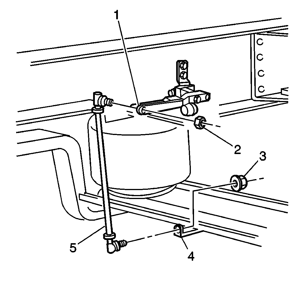
- Remove the locknuts (2, 3) and the washer that connects the height control valve link (5) to the valve (1).
- Remove the height control valve link (5) from the control valve (1).
- Drain the air pressure from the air springs.
- Raise the frame of the vehicle in order to remove the load from the suspension.
- Support the frame using jack stands.
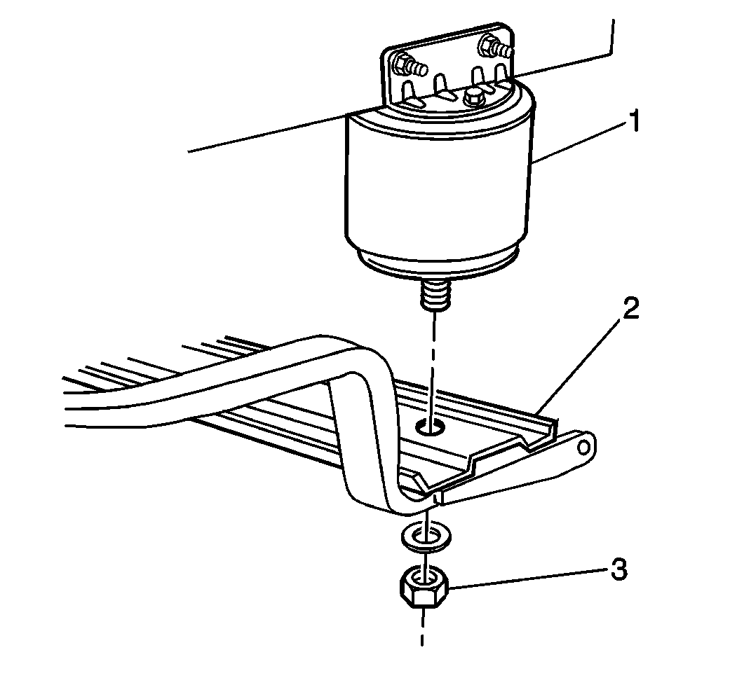
- Remove the locknut (3) and the washer that connect the air spring (1) to the cross channel (2) and to both of the main support beams.
- Raise the cross channel using jacks, if required.


Installation Procedure
- Connect the cross channel (2) to both of the air springs (1).
- Lower the frame.
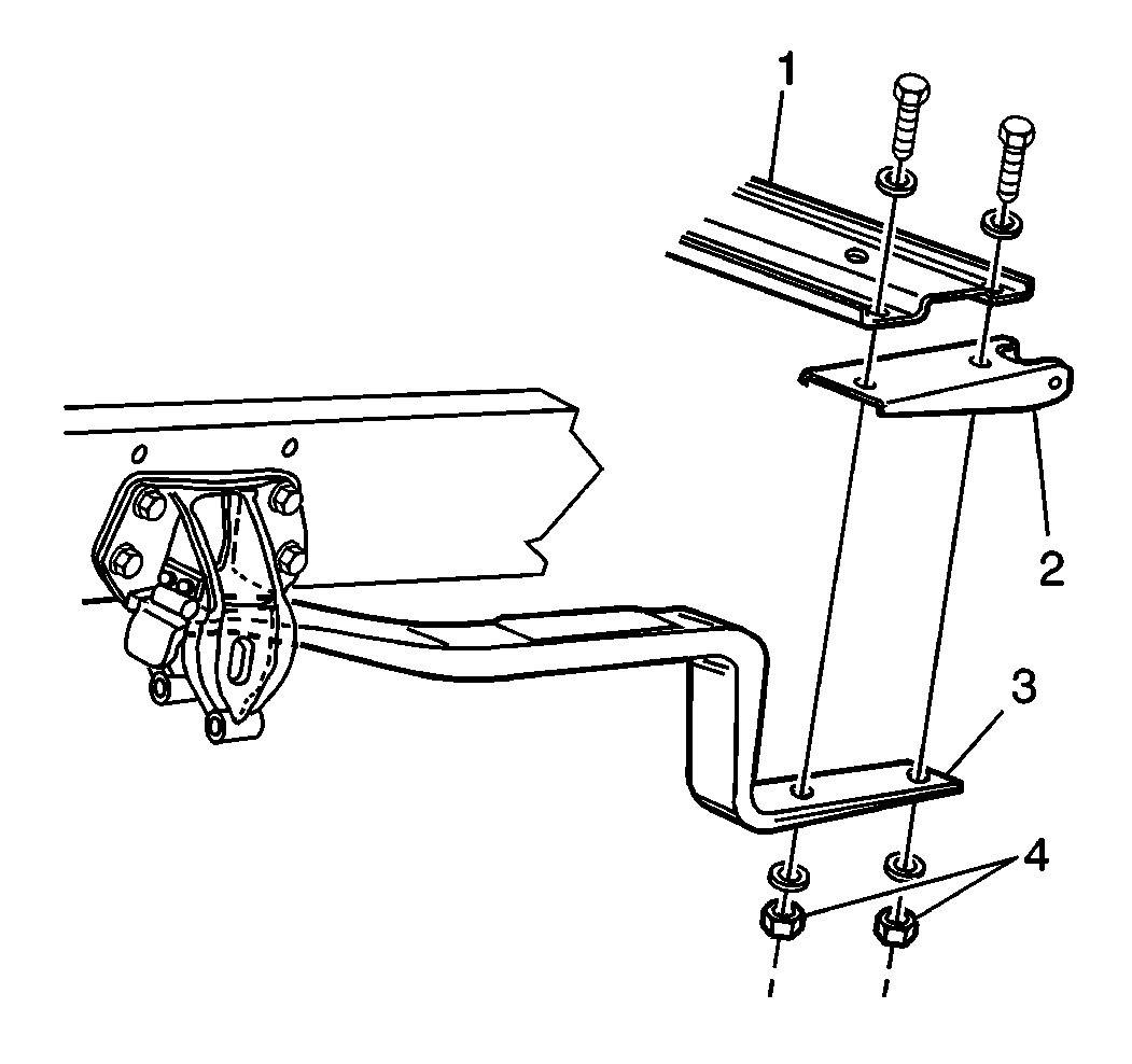
- Pilot the bolt holes onto the main support beam.
- Install the washers and the locknuts (4) that connect the cross channel (1) to the main support beam (3).
- Refill the system with air.
- Unblock the wheels.

Caution: Refer to Fastener Caution in the Preface section.

Tighten
Tighten the locknuts in 37 N·m (50 lb ft) increments to 330 N·m (243 lb ft).
