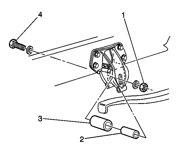
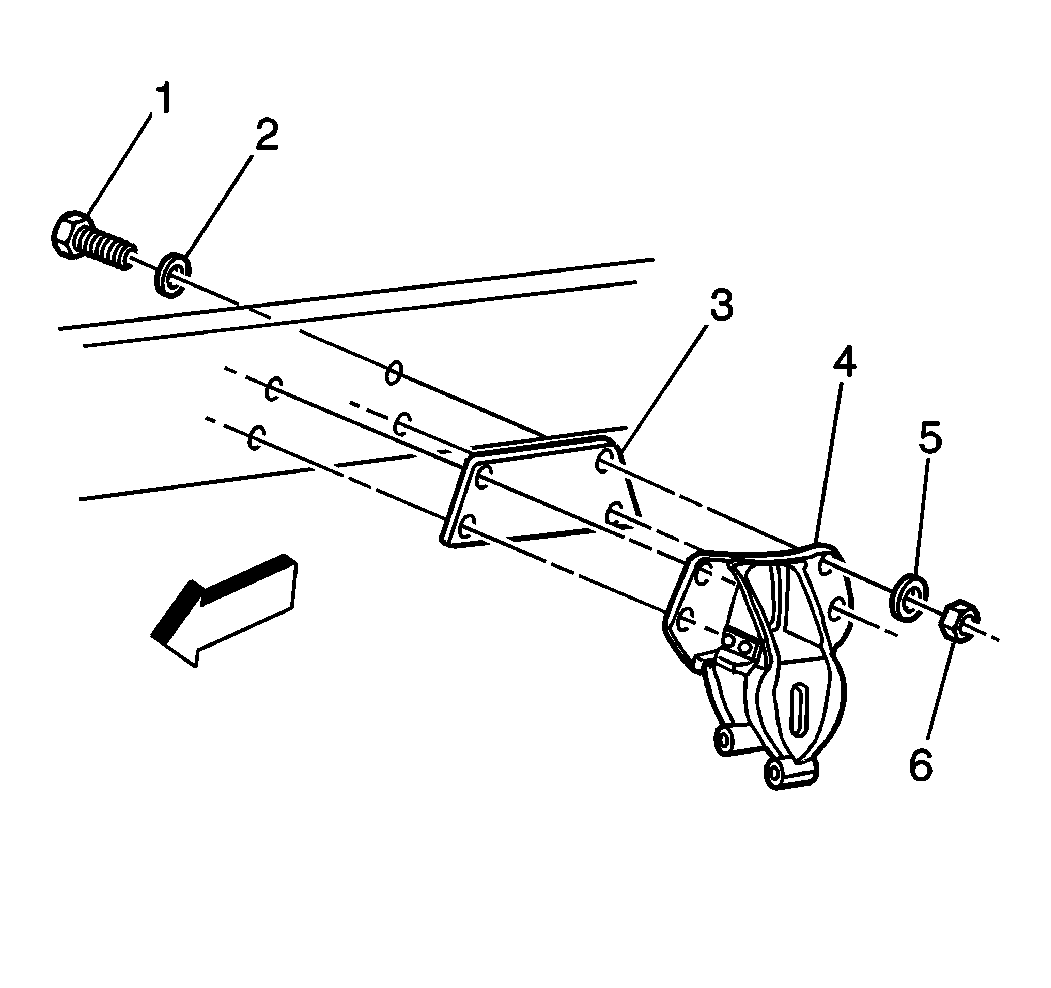
Removal Procedure
- Block the wheels of all of the axles.
- Support the frame using frame stands.
- Support the axles using jack stands.
- Drain the air pressure from the air springs.

- Remove the following components:
Note: The torque rods may remain in place.
- Apply an upward force on the cross tube or lower air spring brackets using a jack or a pry bar. The tips of the main support beams will drop away from the cam surface of the spring hanger brackets.

- Remove the following components:
| • | The insulator fasteners (1, 2, 5, 6) |
| • | The reinforcement plates |
Installation Procedure

- Place a new insulator pad on the spring hanger (4).
Caution: Refer to Fastener Caution in the Preface section.
- Place the retainer plate over the insulator pad.
Tighten
Tighten the 10 mm (0.375 in) hex head self- tapping screws to 34 N·m (25 lb ft).
- Release the jack or pry bar on the cross tube or on the lower air spring brackets. Allow the main support beams to come up to the new insulator pads.

- Install the following components:
| • | The rebound rollers (3) |
Tighten
Tighten the rebound bolt locknuts to 82 N·m (61 lb ft).
- Remove the jack stands.
- Unblock the wheels.


