Rear Brake Caliper Replacement Dayton-Walther Fixed Mount
Removal Procedure
- Apply the parking brake.
- Block the wheels.
- Remove about 2/3 of the brake fluid from the master cylinder reservoir.
- Raise the vehicle. Support the vehicle with safety stands. Refer to Lifting and Jacking the Vehicle.
- Remove the tire and wheel assembly. Refer to Tire and Wheel Removal and Installation.
- Remove the brake pad retainer spring bolt.
- Remove the brake pad retainer spring.
- Push back the pistons on one side of the brake caliper.
- Remove the brake pad.
- Push back the pistons on the other side of the brake caliper.
- Remove the remaining brake pad.
- Remove the brake pipe clip nuts and washers from the rear axle housing studs.
- Remove the brake pipe bolt and 2 gaskets from the caliper.
- Cap or tape the brake pipe fitting in order to prevent contamination.
- Remove the brake caliper bolts and washers.
- Remove the brake caliper from the brake caliper mounting plate.
Note:
• Do not completely drain the master cylinder reservoir. • Drain the fluid from the brake caliper bleeder valve. • Drain the fluid into a suitable container. • Discard the fluid.
Caution: Refer to Brake Caliper Caution in the Preface section.
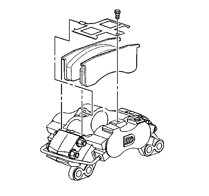
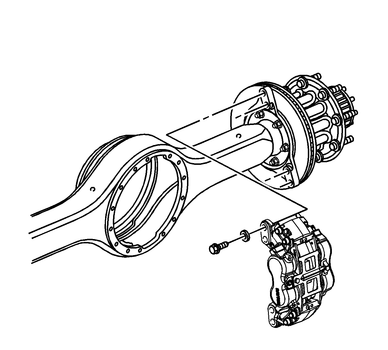
Caution: Do not loosen or remove the four bolts in the brake caliper bridge area. The brake caliper bridge bolts may become loose. If the bridge bolts become loose, replace the brake caliper. Failure to follow these instructions will cause damage to the brake caliper.
Installation Procedure
- Install the brake caliper onto the brake caliper mounting plate.
- Install the brake pipe clips onto the rear axle housing studs.
- Install the brake pipe clip washers and nuts onto the rear axle housing studs.
- Install the brake pipe gaskets and bolt.
- Install the brake pads.
- Install the brake pad retainer spring.
- Install the brake pad retainer spring bolt.
- Fill the master cylinder reservoir with brake fluid. Refer to Master Cylinder Reservoir Filling.
- Bleed the hydraulic brake system. Refer to Hydraulic Brake System Bleeding.
- Pump the brake pedal several times in order to ensure that the pedal is firm and the brake pads are seated.
- Install the tire and wheel assembly. Refer to Tire and Wheel Removal and Installation.
- Lower the vehicle. Refer to Lifting and Jacking the Vehicle.
- Remove the wheel blocks.
Caution: Refer to Fastener Caution in the Preface section.

Tighten
Tighten the brake caliper bolts to 450 N·m (332 lb ft).
Tighten
Tighten the brake pipe clip nuts to 17 N·m (13 lb ft).
Tighten
Tighten the brake pipe bolt to 37 N·m (27 lb ft).

Tighten
Tighten the brake pad retainer spring bolt to 41 N·m (30 lb ft).
Note: Inspect the fluid level in the master cylinder reservoir after pumping the brake pedal.
Warning: Do not move the vehicle until a firm brake pedal is obtained. Failure to obtain a firm pedal before moving vehicle may result in personal injury.
Rear Brake Caliper Replacement TRW Pin Slider
Tools Required
J 44959 T-70 Torx Bit Socket
Warning: Refer to Brake Dust Warning in the Preface section.
Warning: Refer to Brake Fluid Irritant Warning in the Preface section.
Removal Procedure
- Apply the parking brake.
- Block the wheels.
- Remove about 2/3 of the brake fluid from the master cylinder reservoir.
- Raise the vehicle. Support the vehicle with safety stands. Refer to Lifting and Jacking the Vehicle.
- Remove the tire and wheel assembly. Refer to Tire and Wheel Removal and Installation.
- If the rotor removal is needed remove caliper with bracket.
- If equipped with a torx bit, remove the brake caliper mounting bolts using a J 44959 .
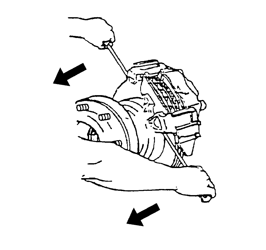
- Compress the piston using 2 screwdrivers to pry between the outer brake caliper housing and the outer brake pad.
- While compressing the pistons, watch the reservoir for possible brake fluid overflow.
- Disconnect the brake hose.
- Cap or tape the brake hose fitting in order to prevent contamination.
- Remove the brake caliper.
Note:
• Do not completely drain the master cylinder reservoir. • Drain the fluid from the brake caliper bleeder valve. • Drain the fluid into a suitable container. Discard the fluid.
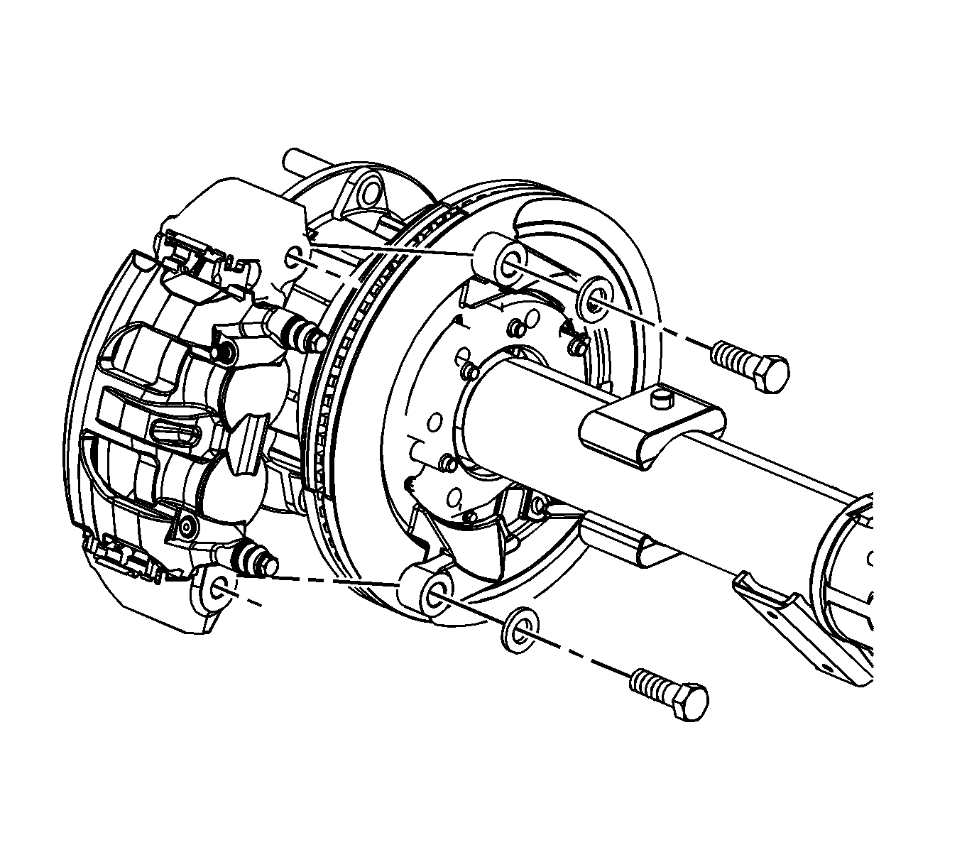
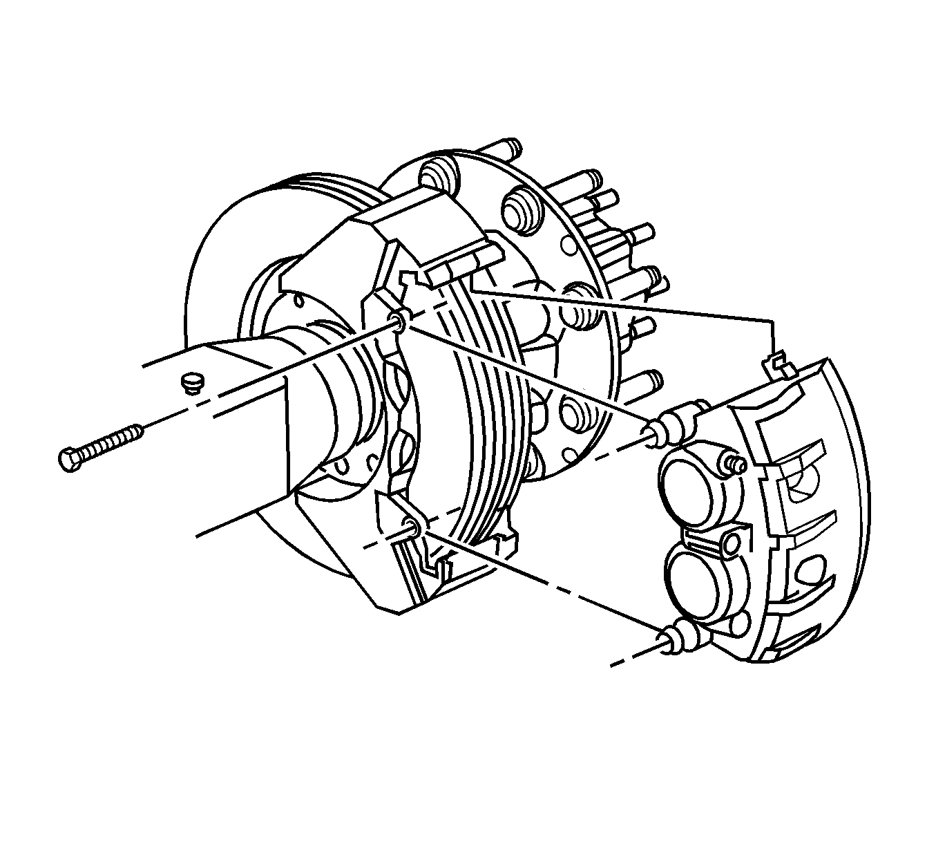
Caution: Refer to Brake Caliper Supporting to Prevent Hose Damage Caution in the Preface section.

Installation Procedure
- Apply a thin coat of brake caliper lubricant GM P/N 89021536 (Canadian P/N 89021538) or equivalent, to the brake caliper support pin surfaces.
- Install the brake hose.
- Loosely assemble the brake hose nut to the brake caliper.
- Install the wheel speed sensor. Refer to Rear Wheel Speed Sensor Replacement.
- If the brake caliper was removed with bracket, install the bracket.
- Install the brake caliper.
- Install the brake caliper mounting bolts.
- Fill the master cylinder reservoir with brake fluid. Use brake fluid GM P/N 1052535, or equivalent. Refer to Master Cylinder Reservoir Filling.
- Bleed the hydraulic brake system. Refer to Hydraulic Brake System Bleeding.
- Pump the brake pedal several times in order to ensure that the pedal is firm and the brake linings are seated.
- Install the tire and wheel assembly. Refer to Tire and Wheel Removal and Installation.
- Lower the vehicle. Refer to Lifting and Jacking the Vehicle.
- Remove the wheel blocks.
Caution: Refer to Installing Hoses without Twists or Bends Caution in the Preface section.
Caution: Refer to Fastener Caution in the Preface section.

Tighten
Tighten the bracket mounting bolts to 450 N·m (332 lb ft).

Tighten
Tighten the mounting bolts to 63 N·m (46 lb ft).
Note: Inspect the fluid level in the master cylinder reservoir after pumping the brake pedal.
