Tie Rod Arm Replacement 16K Axles
Removal Procedure
- Disconnect the tie rod end from the tie rod arm. Refer to Tie Rod Replacement.
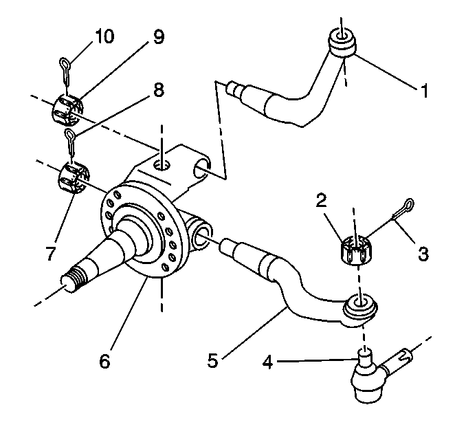
- Vehicles equipped with a cotter pin (8) remove and discard.
- Remove the nut (7).
- Drive the arm (5) from knuckle (6) with a suitable brass drift and hammer.

Note: Do not use heat on components to remove arms.
Installation Procedure
- Install the new tie rod arm (5) with key supplied.
- Install a new nut (7).
- Install a new cotter pin (8), if equipped.
- Install the tie rod end to the tie rod arm. Refer to Tie Rod Replacement.

Caution: Refer to Fastener Caution in the Preface section.
Note:
• Advance the nut (7) to the nearest cotter pin slot. • Do not back off the nut in order to insert a cotter pin.
Tighten
Tighten the nut to 1508 N·m (1112 lb ft).
Tie Rod Arm Replacement 10K/12K/14.6K/Axles
Special Tools
J 26813-B Steering Linkage Puller
Removal Procedure
Note: The tie rod arm is bolted to the steering knuckle. The tie rod arm is non-repairable. Replace the tie rod if damaged. If the tapered hole for the tie rod end is enlarged, replace the tie rod arm and the tie rod end.
- Remove the tie rod end from the tie rod arm. Refer to Tie Rod Replacement.
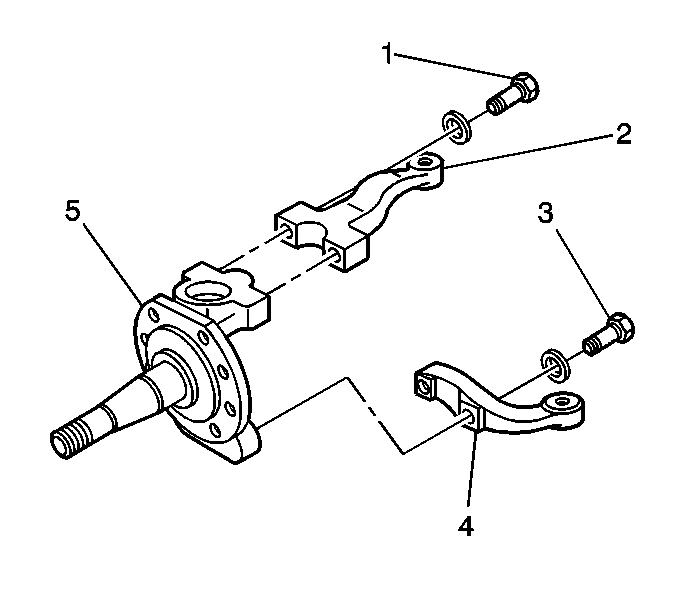
- Remove the tie rod arm bolts (3).
- Remove the tie rod arm (4).

Installation Procedure
- Install the tie rod arm (4) to the knuckle (5).
- Install the tie rod arm bolts (3).
- Install the tie rod ball joint to the tie rod arm. Refer to Tie Rod Replacement.
- Adjust the toe-in. Refer to Wheel Alignment - Steering Wheel Angle and/or Front Toe Adjustment.

Caution: Refer to Fastener Caution in the Preface section.
Tighten
Tighten the tie rod arm bolts to 1068 N·m (788 lb ft).
Note:
• Advance the tie rod ball joint nut to the nearest cotter pin slot. • Do not back off a tie rod ball joint nut in order to insert a cotter pin.
