For 1990-2009 cars only
Warning: Refer to Brake Fluid Irritant Warning in the Preface section.
Caution: Refer to Brake Fluid Effects on Paint and Electrical Components Caution in the Preface section.
Removal Procedure
Note: Flushing the system is required when dirt, sludge or water is found in the system. Flushing the system involves running clean fluid through the system until the draining fluid appears clean.
- Block the wheels.
- Disconnect the electrical connectors from the electrohydraulic pump and the flow switch.
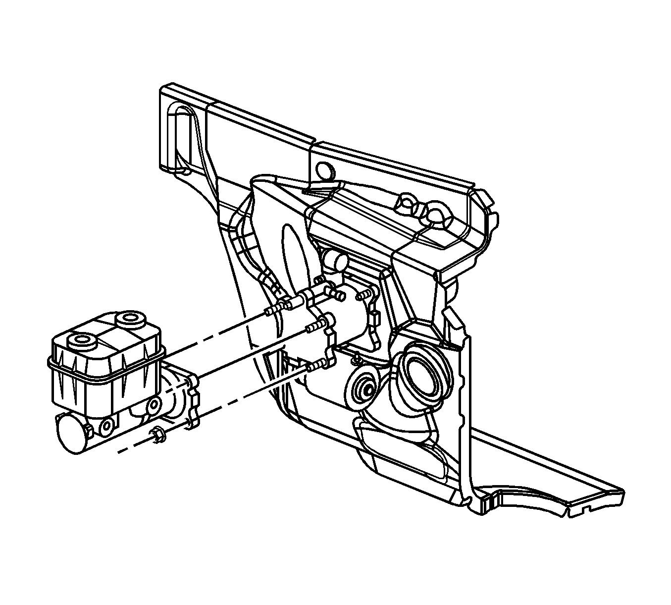
- Remove the master cylinder. Refer to Master Cylinder Replacement.
- Disconnect the hoses from the booster. Refer to Power Brake Booster Inlet Hose Replacement and Power Brake Booster Outlet Hose Replacement.
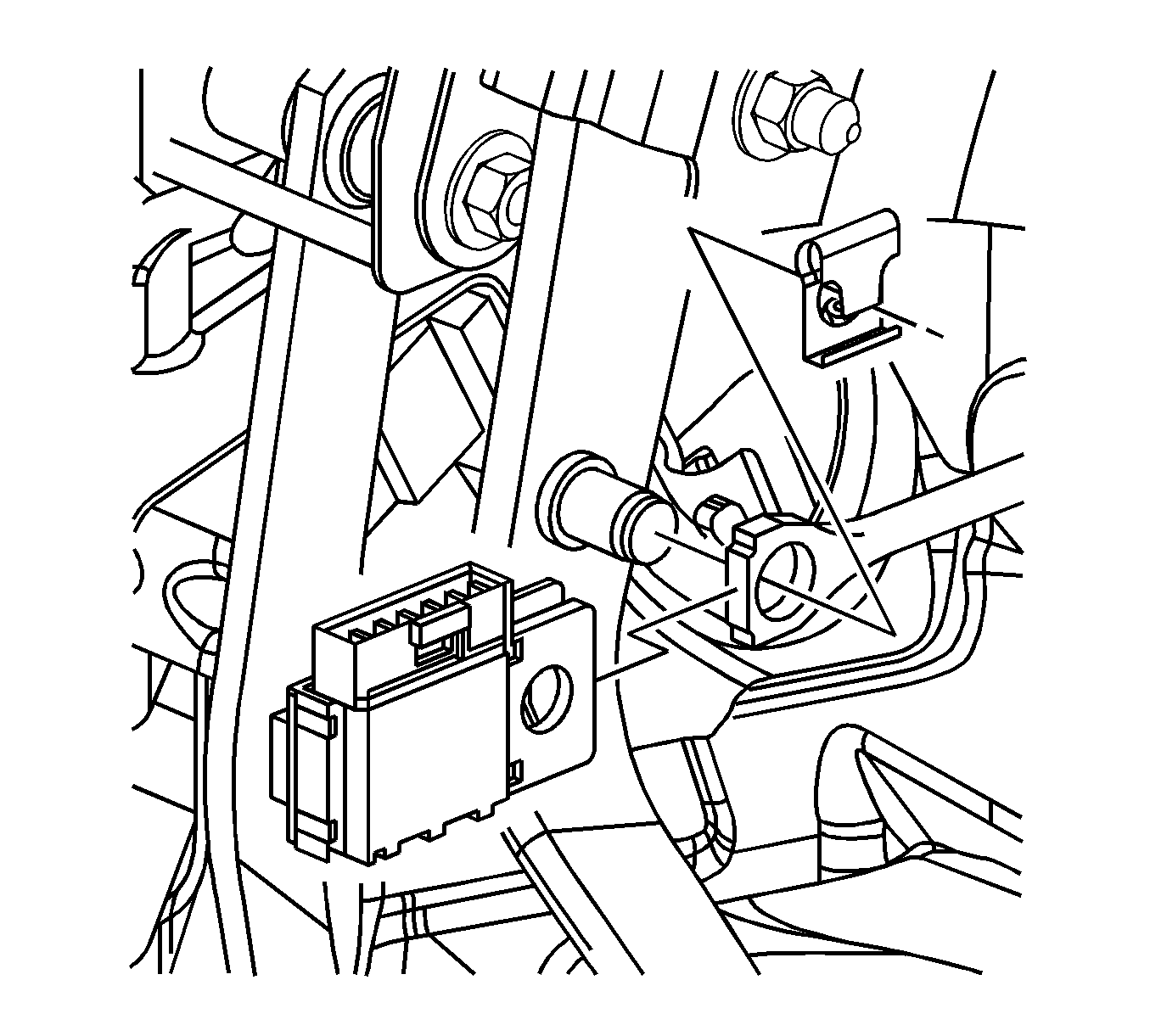
- Remove the booster pump rod retainer from the lever.
- Remove the stop lamp switch from the lever.
- Remove the booster pump rod from the lever.
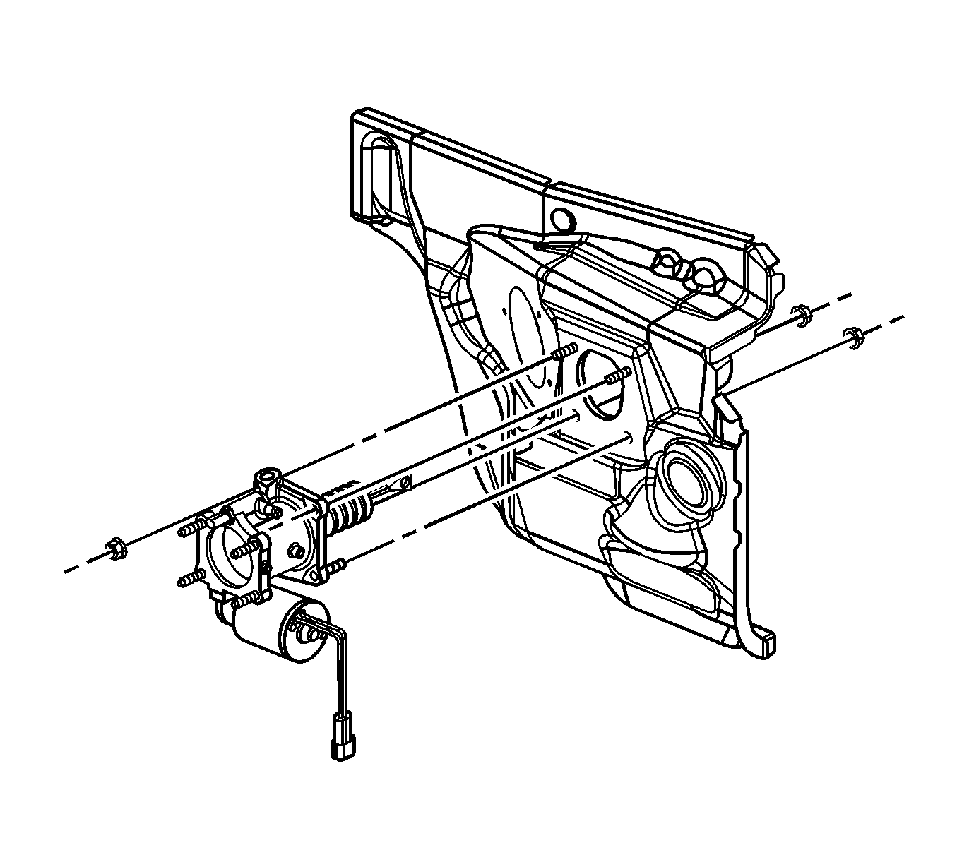
- Remove the nuts at the booster.
- Remove the booster assembly.
- Inspect the area between the power brake booster and the power brake booster pump for fluid leakage. If fluid leakage is evident, replace the O-ring seals between the booster and the pump. Refer to Power Brake Booster Pump Replacement.

Position the master cylinder away from the booster head. Secure the master cylinder in an upright position.


Installation Procedure
- Install the booster assembly to the vehicle.
- Install the nuts at the booster.
- Install the booster pump rod to the lever.
- Install the stop lamp switch to the lever.
- Install the booster pump rod retainer.
- Install the hoses to the booster. Refer to Power Brake Booster Outlet Hose Replacement and Power Brake Booster Inlet Hose Replacement.
- Install the master cylinder. Refer to Master Cylinder Replacement.
- Install the electrical connectors to the electrohydraulic pump and the flow switch.
- Fill the hydraulic pump reservoir.
- Bleed the system.
- Inspect the vehicle for the proper brake operation.
- Remove the wheel blocks.

Caution: Refer to Fastener Caution in the Preface section.
Tighten
Tighten the nuts to 50 N·m (37 lb ft).


