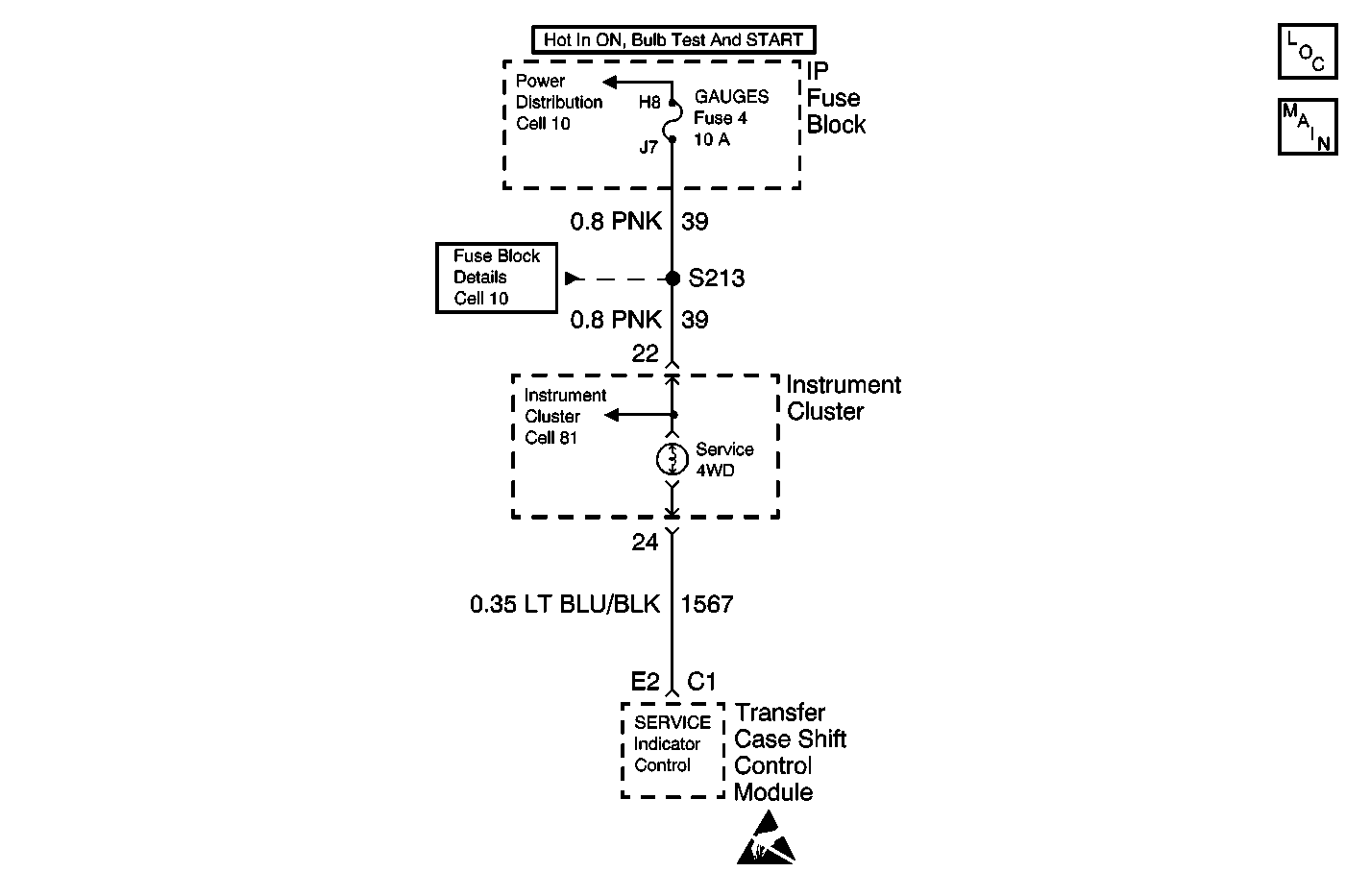
Circuit Description
The transfer case shift control module controls the SERVCE indicator (AWD/4WD) lamp, located in the instrument cluster, by grounding the SERVICE Indicator lamp control circuit. Voltage to the lamp is supplied via a common GAUGE Fuse, which feeds all of the gauges in the instrument cluster.
Conditions for Setting the DTC
After the transfer case shift control module commands the lamp on, the module senses a voltage greater than 7 V on the SERVICE Indicator lamp output circuit.
Conditions for Clearing the DTC
| • | The transfer case shift control module will clear the DTC if the condition for setting the DTC no longer exists. |
| • | A history DTC will clear after 100 consecutive ignition cycles without a fault present. |
| • | Use a scan tool in order to clear history DTCs. |
Test Description
The numbers below refer to the step numbers on the diagnostic table.
-
Look for the visual operation of the SERVICE indicator lamp. Command both the ON and OFF states.
-
Tests the operation of the SERVICE indicator lamp circuit.
-
Tests the SERVICE indicator lamp output circuit for an open, short to ground or high resistance.
Step | Action | Value(s) | Yes | No |
|---|---|---|---|---|
1 | Was the Transfer Case Diagnostic System Check performed? | -- | Go to Step 2 | Go to Diagnostic System Check |
Does the SERVICE Indicator lamp turn ON and OFF with each command? | -- | Go to Step 3 | ||
Does the SERVICE indicator lamp turn ON? | -- | Go to Step 6 | Go to Step 4 | |
Test the SERVICE indicator lamp control circuit for an open, short to ground, or high resistance. Refer to Circuit Testing and Wiring Repairs in Wiring Systems. Was the condition found and corrected? | -- | Go to Step 7 | Go to Step 5 | |
5 | Remove the instrument cluster for repair. Refer to Instrument Cluster Replacement in Instrument Panel, Gauges and Console. Is the repair complete? | -- | Go to Step 7 | -- |
6 | Replace the transfer case shift control module. Refer to Transfer Case Shift Control Module Replacement . Is the repair complete? | -- | Go to Step 7 | -- |
7 |
Does the DTC reset? | -- | Go to Step 2 | System OK |
