Tie Rod Replacement All Except C3500HD
Tools Required
| • | J 29193
Steering
Linkage Installer (12 mm) |
Removal Procedure
- Raise the vehicle. Refer to
Lifting and Jacking the Vehicle
in General Information.
- Suitably support the vehicle with jack stands.
Important: Do NOT reuse the nut.

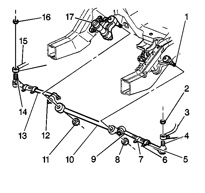
- Remove the nut (16) from
the outer tie rod ball stud (14).
- Use the J 6627-A
in order to remove the outer tie rod ball stud from the steering knuckle
(15).
Important: Do NOT reuse the nut.
- Remove the nut (12) from the inner tie rod ball stud.
- Use the J 6627-A
in order to remove the inner tie rod ball stud from the relay rod
(10).
- Remove the tie rod ends from the adjuster tube.
| 7.1. | Loosen the clamp nuts. |
| 7.3. | Unscrew the tie rods. |
- Inspect the following components:
| 8.1. | The tie rod ends for damage |
| 8.2. | The tie rod end seals for excessive wear |
| 8.3. | The ball stud threads for damage |
| 8.4. | The adjuster tubes for bending or damaged threads |
- Clean the tapered surfaces.
- Clean the threads on the ball stud and in the ball stud nut.
Installation Procedure
- If the tie rod end was removed, lubricate the tie rod threads
with chassis lubricant.
- Install the tie rod end to the adjuster tube.
- The number of threads on both the inner and the outer rod ends
must be equal within three threads.
Notice: Use the correct fastener in the correct location. Replacement fasteners
must be the correct part number for that application. Fasteners requiring
replacement or fasteners requiring the use of thread locking compound or sealant
are identified in the service procedure. Do not use paints, lubricants, or
corrosion inhibitors on fasteners or fastener joint surfaces unless specified.
These coatings affect fastener torque and joint clamping force and may damage
the fastener. Use the correct tightening sequence and specifications when
installing fasteners in order to avoid damage to parts and systems.
- Install the inner
tie rod ball studs to the relay rod.
The seal must be on the stud.
Tighten
Tighten the inner tie rod ball stud to 54 N·m (40 lb ft)
in order to seat the tapers.
- Use the J 29193
in
order to install the inner tie rod ball stud.
- Install the new prevailing torque nut to the inner tie rod ball
stud.
Tighten
Tighten the new prevailing torque nut to 62 N·m (46 lb ft).

- Install the outer tie
rod ball studs to the steering knuckle (15).
Tighten
Tighten the outer tie rod ball stud to 54 N·m (40 lb ft)
in order to seat the tapers.
Use the J 29193
in
order to install the outer tie rod ball stud.
- Install the new prevailing torque nut to the outer rod ball studs.
Tighten
Tighten the new prevailing torque nut to 62 N·m (46 lb ft).
- Adjust the front toe. Refer to
Wheel Alignment Measurement
in Wheel Alignment.
Tie Rod Replacement C3500HD
Removal Procedure

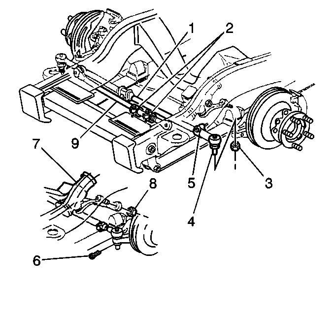
- The heavy duty suspension uses only one adjustable tie rod end, connected
to the left steering knuckle spindle.
| 1.1. | A ball socket is found at the end of the tie rod assembly rod
and attaches to the steering knuckle spindle. |
| 1.2. | The tie rod assembly rod attaches to the steering gear (7) by
means of a drag link (9) and ball socket with an adjuster sleeve near the
Pitman arm stud hole. |
- Remove the cotter pin (6) at the ball stud (4).
- Remove the nut (8) from the ball stud.
- Loosen the nut on the adjuster clamp.
- Remove the ball stud and tie rod end from the tie rod assembly
(1).
- Inspect the following parts:
| 6.1. | The tie rod end for damage |
| 6.2. | The tie rod end seals for excessive wear |
| 6.3. | The threads on the relay rod and the tie rod end for damage |
| 6.4. | The ball stud threads for damage |
| 6.5. | The adjuster tubes for bending or damaged threads |
| 6.6. | Clean the tapered surfaces |
| 6.7. | Clean the threads on the ball stud and in the ball stud nut |
Installation Procedure

- Install the ball stud (4) and the tie rod end to the tie rod assembly
(1).
- Install the ball stud into the steering knuckle.
Notice: Use the correct fastener in the correct location. Replacement fasteners
must be the correct part number for that application. Fasteners requiring
replacement or fasteners requiring the use of thread locking compound or sealant
are identified in the service procedure. Do not use paints, lubricants, or
corrosion inhibitors on fasteners or fastener joint surfaces unless specified.
These coatings affect fastener torque and joint clamping force and may damage
the fastener. Use the correct tightening sequence and specifications when
installing fasteners in order to avoid damage to parts and systems.
- Install the nut
(8) to the ball stud.
Tighten
Tighten the nut to 88 N·m (65 lb ft).
- Install the tie rod end.
- Install the cotter pin (6).
| 5.1. | Align the cotter pin slot to the nut with the hole through the
tie rod stud. |
| 5.2. | Do NOT back off the nut in order to align the slot. |
- Adjust the front toe. Refer to
Wheel Alignment Measurement
in Wheel Alignment.
- Install the adjuster clamp nuts.
Tighten
Tighten the clamp nut to 104 N·m (77 lb ft).


