Steering Knuckle Replacement Coil Spring Suspension
| • | J 43631 Ball Joint Remover |
| • | J 45851 Ball Joint Separator Protector Adapters |
Removal Procedure
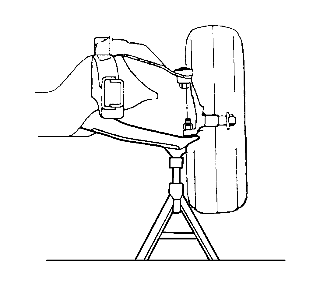
- Raise and support the vehicle. Refer to Lifting and Jacking the Vehicle in General Information.
- Remove the tire and wheel. Refer to Tire and Wheel Removal and Installation in Tires and Wheels.
- Support the lower control arm with a suitable jack.
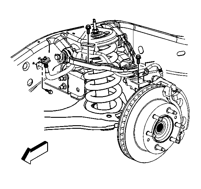
- Remove the wheel hub and bearing. Refer to Front Wheel Hub, Bearing, and Seal Replacement .
- Disconnect the Electronic Suspension Control (ESC) link rod from the sensor, if equipped. Refer to Electronic Suspension Front Position Sensor Link Assembly Replacement in Electronic Suspension Control.
- Disconnect the outer tie rod from the knuckle. Refer to Tie Rod Replacement in Steering Linkage (Non- Rack and Pinion).
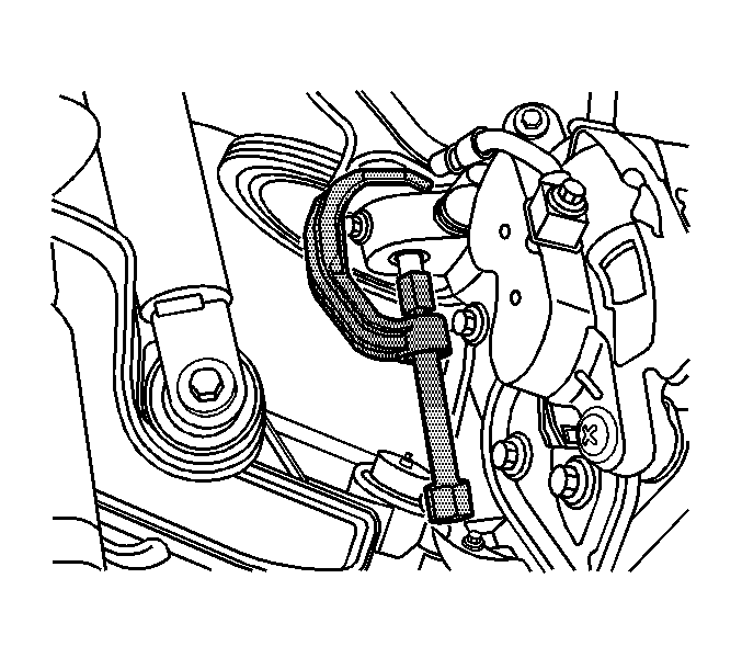
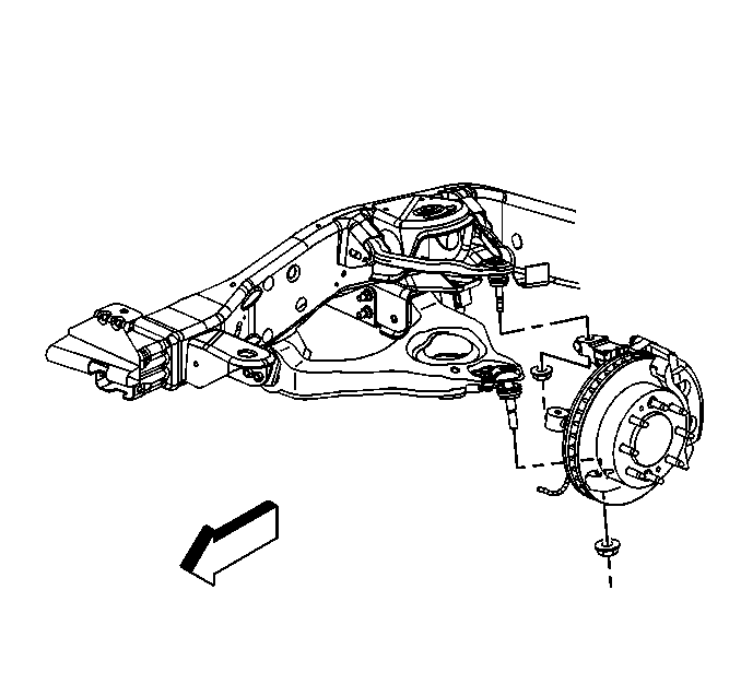
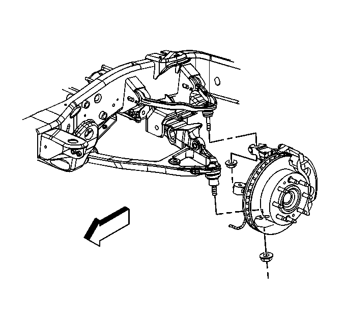
- Remove the brake hose bracket retaining bolt from the knuckle.
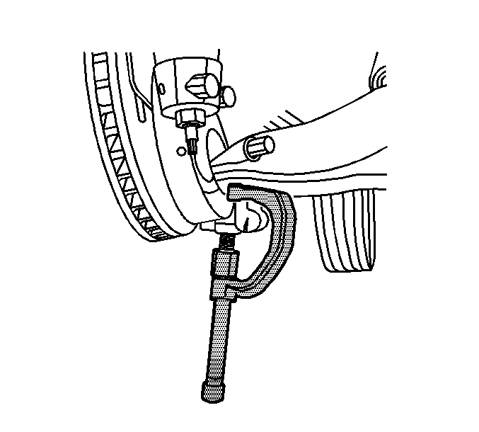
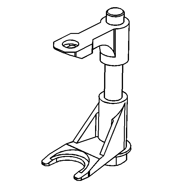
- Remove the retaining nut and separate the upper ball joint from the steering knuckle using the J 43631 and J 45851 .
- Remove the retaining nut and separate the lower ball joint from the steering knuckle using the J 43631 and J 45851 .
- Remove the steering knuckle.
Installation Procedure
- Clean all grease and contaminants from the tapered section and the threads of the upper ball joint, the lower ball joint, and the tie rod end.
- Clean and inspect the taper holes and the mounting surfaces of the steering knuckle. If any of the tapered holes are elongated, out of round, or damaged, the replace the steering knuckle.
- Install the steering knuckle.
- Connect the lower ball joint to the steering knuckle and install the retaining nut.
- Connect the upper ball joint to the steering knuckle and install the retaining nut.
- Install the brake hose bracket retaining bolt to the knuckle.
- Install the outer tie rod to the steering knuckle. Refer to Tie Rod Replacement in Steering Linkage (Non- Rack and Pinion).
- Install the wheel hub and bearing. Refer to Front Wheel Hub, Bearing, and Seal Replacement .
- Connect the ESC link rod to the sensor, if equipped. Refer to Electronic Suspension Front Position Sensor Link Assembly Replacement in Electronic Suspension Control.
- Install the tire and wheel. Refer to Tire and Wheel Removal and Installation in Tires and Wheels.
- Remove the safety stands.
- Lower the vehicle .
Notice: Use the correct fastener in the correct location. Replacement fasteners must be the correct part number for that application. Fasteners requiring replacement or fasteners requiring the use of thread locking compound or sealant are identified in the service procedure. Do not use paints, lubricants, or corrosion inhibitors on fasteners or fastener joint surfaces unless specified. These coatings affect fastener torque and joint clamping force and may damage the fastener. Use the correct tightening sequence and specifications when installing fasteners in order to avoid damage to parts and systems.
Tighten
Tighten the retaining nut to 100 N·m (74 lb ft).
Tighten
Tighten the retaining nut to 50 N·m (37 lb ft).
Tighten
Tighten the bolt to 9 N·m (80 lb in).
Steering Knuckle Replacement Torsion Bar Suspension
| • | J 43631 Ball Joint Remover |
| • | J 45851 Ball Joint Separator Protector Adapters |
| • | J-42188-B Ball Joint Separator |
Removal Procedure
- Raise and support the vehicle. Refer to Lifting and Jacking the Vehicle in General Information.
- Remove the tire and wheel. Refer to Tire and Wheel Removal and Installation in Tires and Wheels.
- Support the control arm with a safety stand.
- Disconnect the Electronic Suspension Control (ESC) link rod from the sensor, if equipped. Refer to Electronic Suspension Front Position Sensor Link Assembly Replacement in Electronic Suspension Control.
- Unload the torsion bars. Refer to Torsion Bar Replacement .
- Remove the wheel hub and bearing assembly. Refer to Front Wheel Hub, Bearing, and Seal Replacement .
- Remove the outer tie rod to the steering knuckle. Refer to Tie Rod Replacement in Steering Linkage (Non- Rack and Pinion).
- Remove the brake hose bracket retaining bolt from the steering knuckle.
- Remove the upper control arm retaining nut and separate the upper ball joint from the steering knuckle using the J-42188-B .
- Remove the lower ball joint retaining nut. Separate the lower ball joint from the steering knuckle using the J 43631 and J 45851 .
- Remove the steering knuckle.
Installation Procedure
- Clean all grease and contaminants from the tapered section and the threads of the upper ball joint, the lower ball joint, and the tie rod end.
- Clean and inspect the taper holes and the mounting surfaces of the steering knuckle. If any of the tapered holes are elongated, out of round, or damaged, replace the steering knuckle.
- Install the steering knuckle.
- Connect the lower ball joint to the steering knuckle and install the retaining nut.
- Connect the upper ball joint to the steering knuckle and install the retaining nut.
- Install the brake hose and the bracket retaining bolt to the steering knuckle
- Install the outer tie rod to the steering knuckle. Refer to Tie Rod Replacement in Steering Linkage (Non- Rack and Pinion).
- Install the wheel hub and bearing assembly. Refer to Front Wheel Hub, Bearing, and Seal Replacement .
- Connect the ESC link rod to the sensor, if equipped. Refer to Electronic Suspension Front Position Sensor Link Assembly Replacement in Electronic Suspension Control.
- Install the tire and wheel. Refer to Tire and Wheel Removal and Installation in Tires and Wheels.
- Load the torsion bars. Refer to Torsion Bar Replacement .
- Remove the safety stands.
- Lower the vehicle .
- Check the wheel alignment. Refer to Wheel Alignment Measurement in Wheel Alignment.
Notice: Refer to Fastener Notice in the Preface section.
Tighten
Tighten the lower control arm retaining nut to 100 N·m (74 lb ft).
Tighten
Tighten the upper control arm retaining nut to 50 N·m (37 lb ft).
Tighten
Tighten the bolt to 9 N·m (80 lb in).
