For 1990-2009 cars only
Tools Required
| • | J 36850 Transjel® Lubricant |
| • | J 8614-01 Countershaft Driven Gear Holder |
| • | J 35425 Rack Seal and Bearing Installer |
| • | J 34826 Hub Nut Socket - 36 mm |
| • | J 26900-6 Dial Caliper |
| • | J 7872 Magnetic Base Indicator Set |
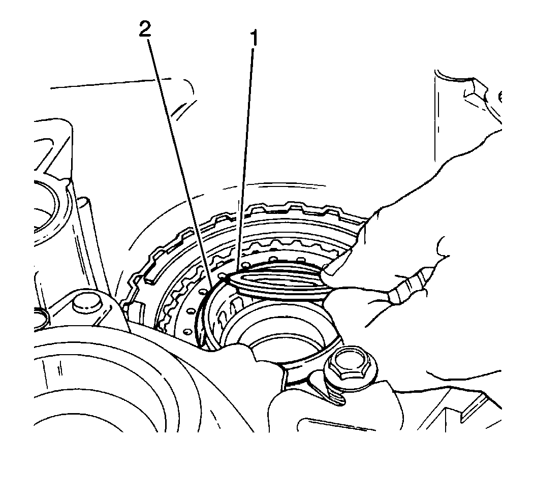
- Apply J 36850 to the underdrive sun gear inner thrust bearing (1).
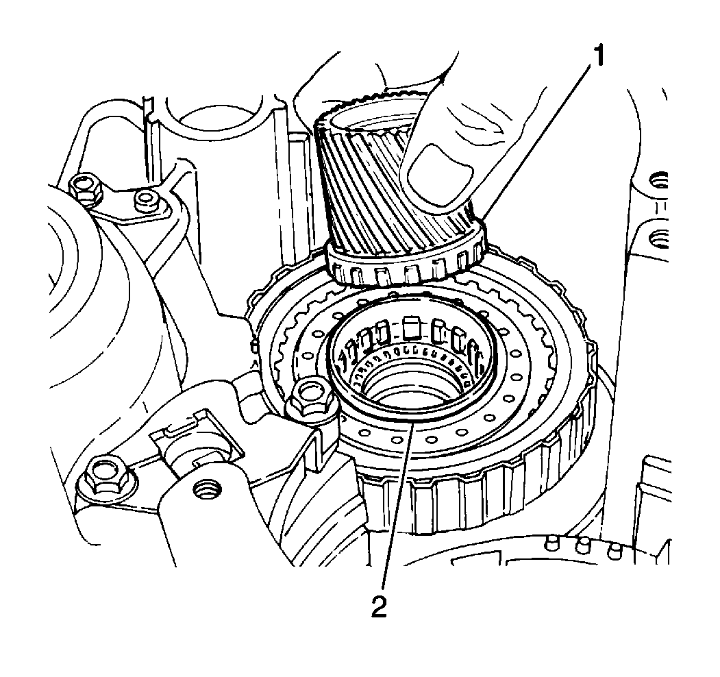
- Install the underdrive sun gear into the underdrive thrust bearing. Install the assembly into the underdrive clutch drum (2).
- Install the underdrive sun gear into the underdrive clutch drum (2).
- Align the inner teeth of the underdrive clutch discs.
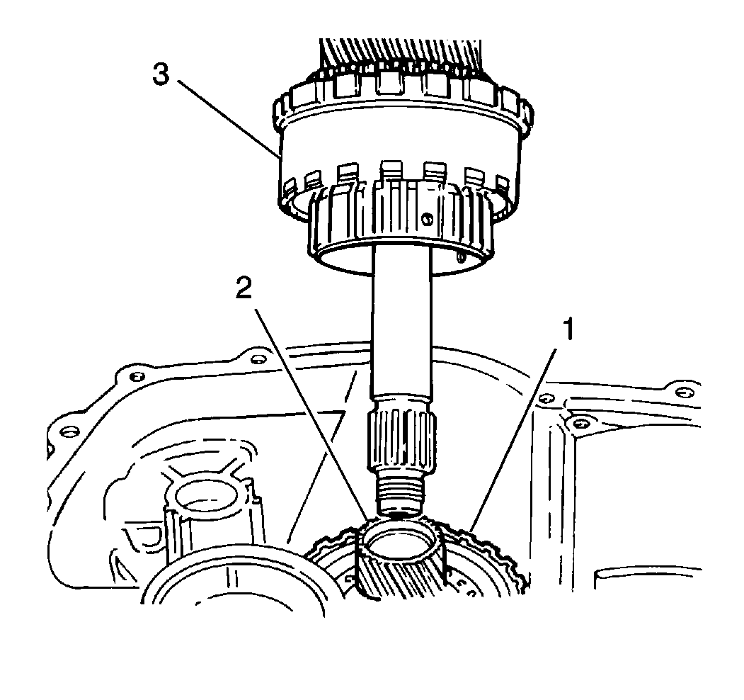
- Install the countershaft assembly (3) into the underdrive clutch assembly (1).
- Measure the countershaft assembly (1) depth using a J 26900-6 and a straight edge (A).
- Apply J 36850 to the countershaft driven gear thrust bearing.
- Install the countershaft driven gear thrust bearing into transaxle case (1).
- Install the countershaft driven gear (1) onto the countershaft using a J 35425 and a hammer while supporting the countershaft.
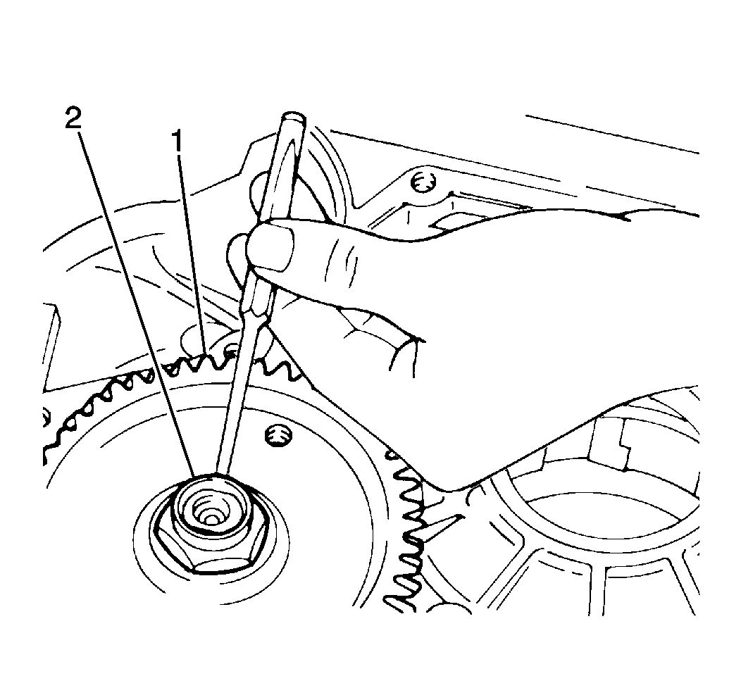
- Install a J 8614-01 onto the countershaft locknut driven gear stationary during the countershaft locknut installation.
- Install the countershaft driven gear locknut onto the countershaft driven gear (1) using a J 34826 with a J 8614-01 .
- Remove the J 8614-01 from the countershaft driven gear.
- Measure the countershaft assembly end play using a J 7872 .
- Stake the countershaft driven gear locknut (2).
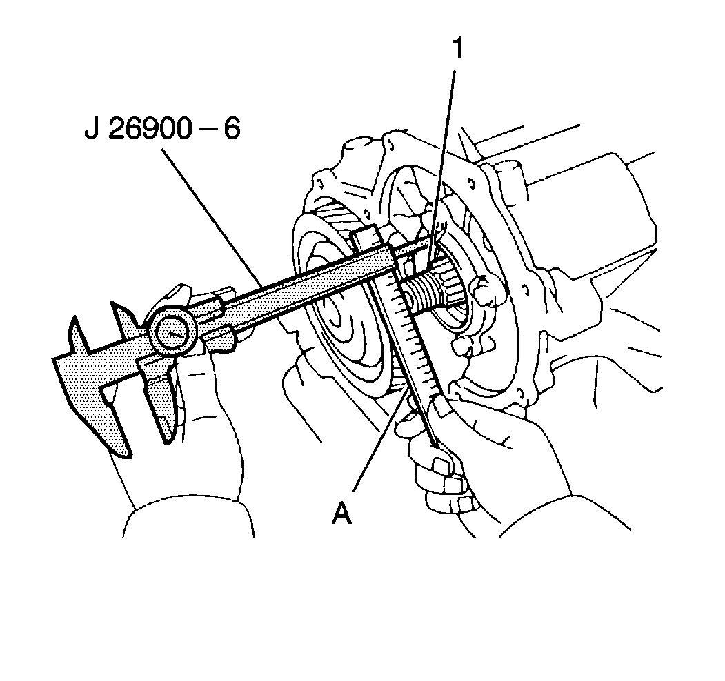
| • | Measure the distance between the end of the countershaft and the bolt seat underdrive clutch drum support. Countershaft assembly installation depth should measure 30.3-32.5 mm (1.193-1.280 in). |
| • | If the countershaft assembly installation depth does not fall within specification, remove the countershaft assembly installation depth falls within specification. |
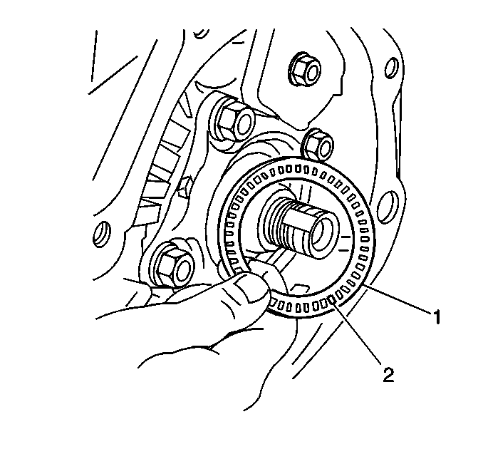
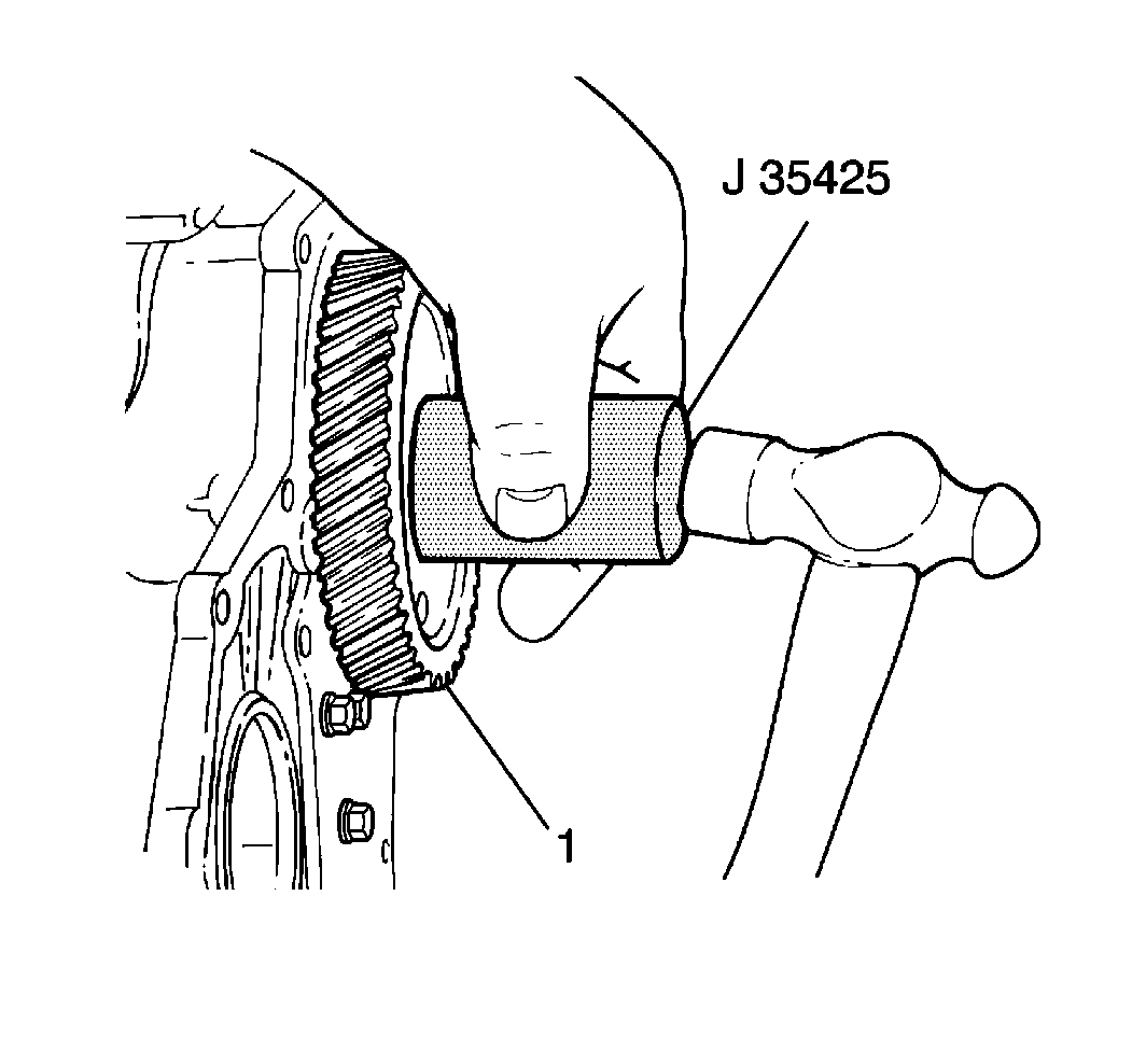
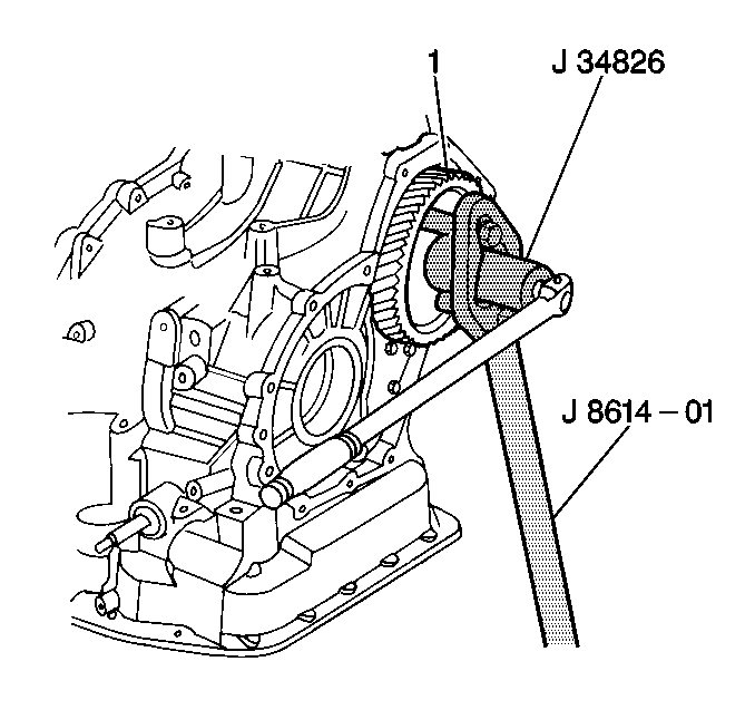
Notice: Refer to Fastener Notice in the Preface section.
Tighten
Tighten the countershaft driven gear locknut to 177 N·m (131 lb ft).
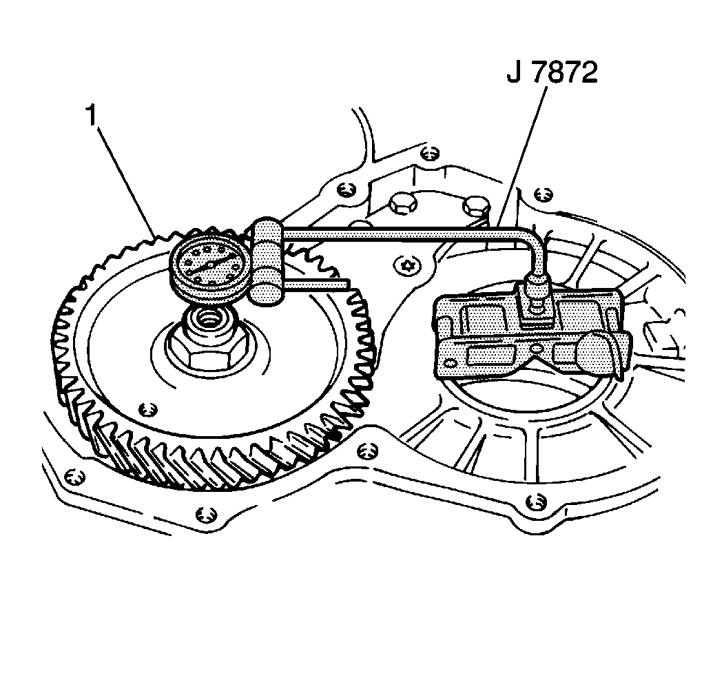
| • | Place the J 7872 on the end of the countershaft assembly and gently move the countershaft up and down while observing the J 7872 . |
| • | The countershaft assembly (1) end play should fall within 0.2-0.9 mm (0.008-0.035 in). |
| • | If the countershaft assembly does not fall within specification, remove the countershaft assembly and reinstall until the countershaft assembly end play is within specification. |
