For 1990-2009 cars only
Steering Knuckle Replacement 1500
Removal Procedure
- Raise and support the vehicle. Refer to Lifting and Jacking the Vehicle .
- Remove the tire and wheel. Refer to Tire and Wheel Removal and Installation .
- Remove the wheel drive shaft, if equipped. Refer to Wheel Drive Shaft Replacement .
- Remove the wheel bearing and hub assembly. Refer to Front Wheel Hub, Bearing, and Seal Replacement .
- Remove the outer tie rod end from the knuckle. Refer to Steering Linkage Outer Tie Rod Replacement .
- Separate the upper control arm from the knuckle. Refer to Upper Control Arm Replacement .
- Separate the lower control arm from the knuckle. Refer to Lower Control Arm Replacement .
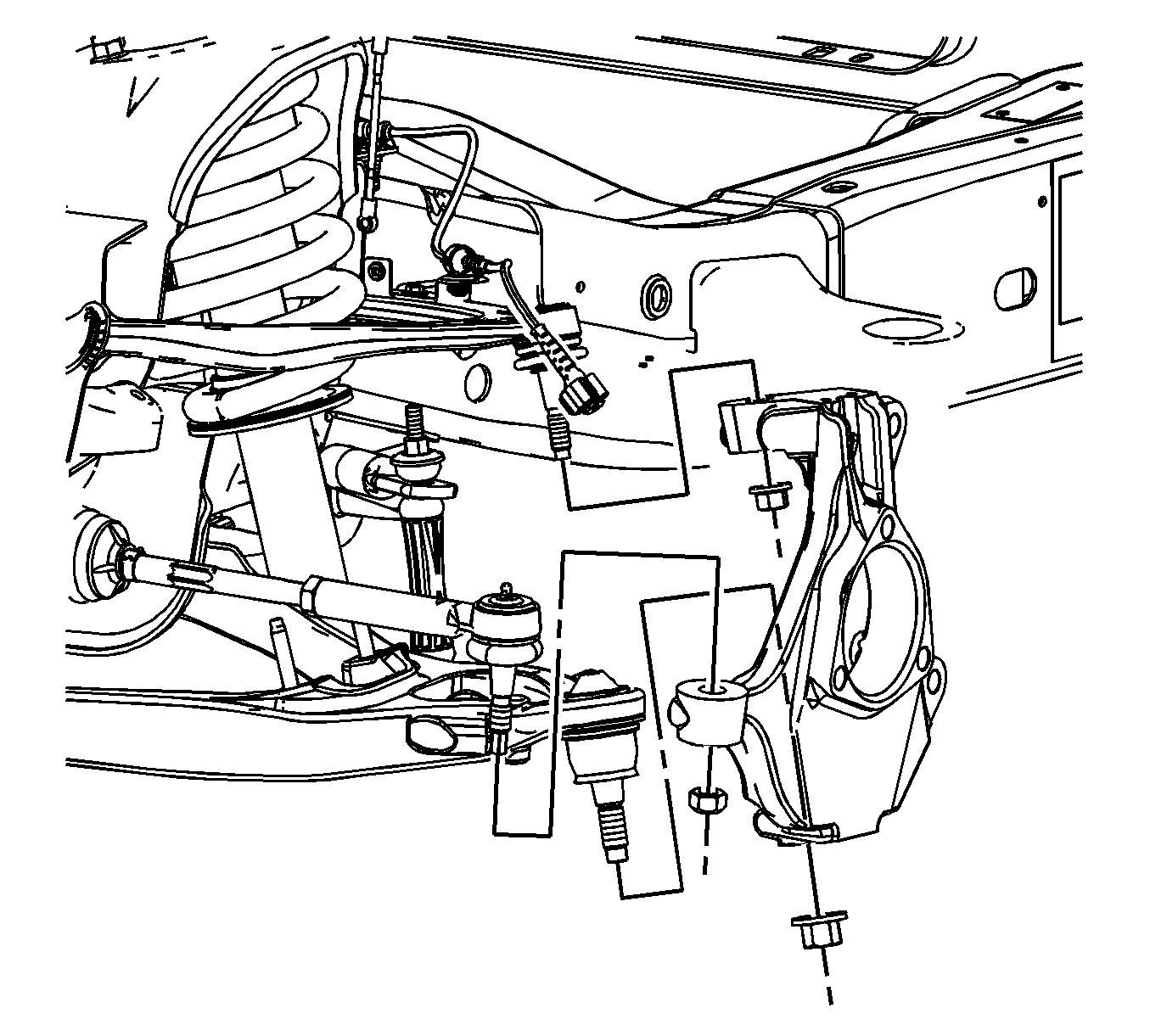
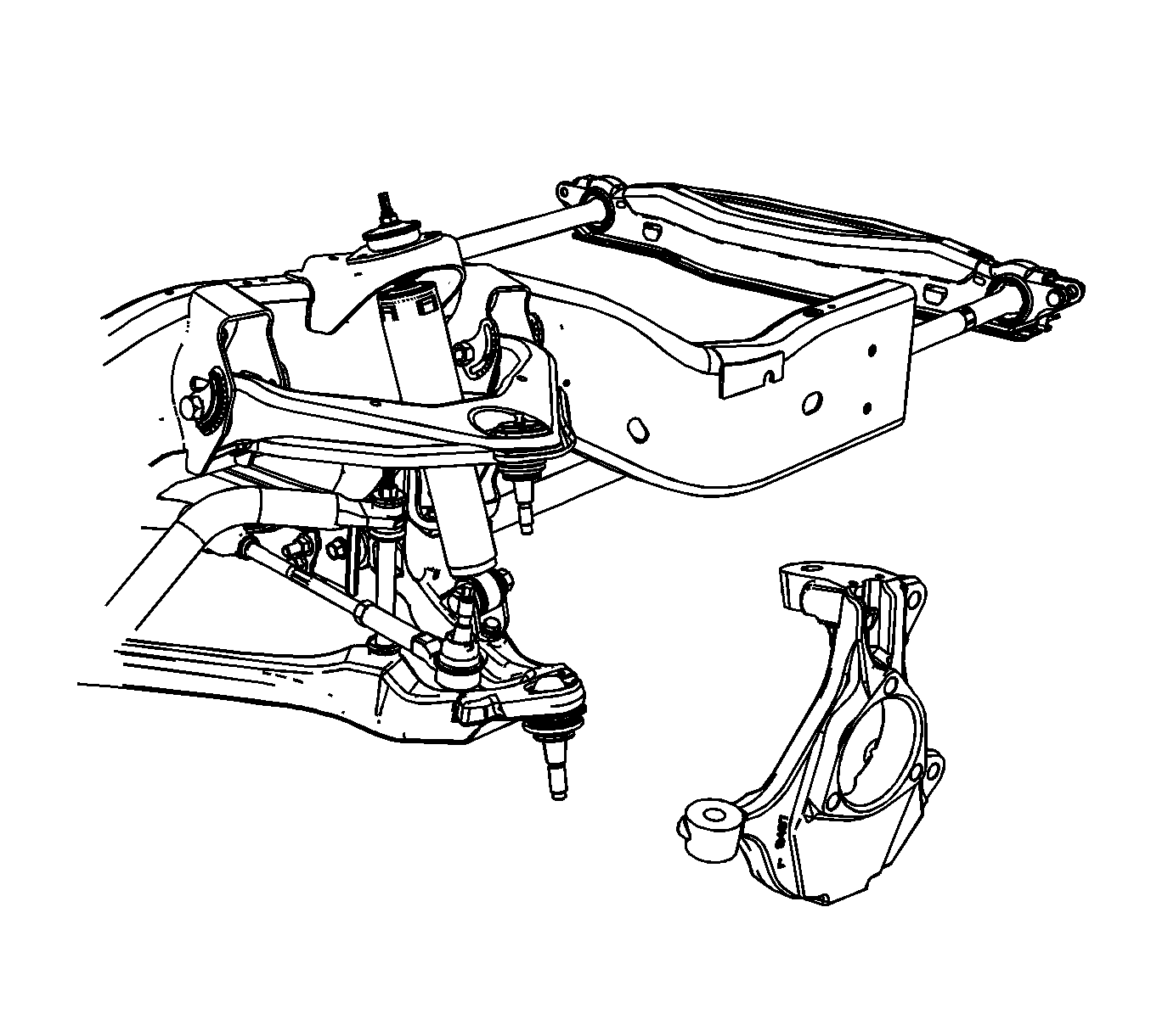
- Remove the knuckle from the vehicle.

Installation Procedure
- Install the lower ball joint in the knuckle. Refer to Lower Control Arm Replacement .
- Install upper ball joint in the knuckle. Refer to Upper Control Arm Replacement .
- Install the outer tie rod end in the knuckle. Refer to Steering Linkage Outer Tie Rod Replacement .
- Install the wheel bearing and hub assembly. Refer to Front Wheel Hub, Bearing, and Seal Replacement .
- Install the wheel drive shaft, if equipped. Refer to Wheel Drive Shaft Replacement .
- Install the tire and wheel. Refer to Tire and Wheel Removal and Installation .
- Remove the support and lower the vehicle.
- Verify the wheel alignment. Refer to Wheel Alignment Specifications .

Steering Knuckle Replacement 2500
Removal Procedure
- Remove the tire and wheel. Refer to Tire and Wheel Removal and Installation .
- Remove the wheel drive shaft, if equipped. Refer to Wheel Drive Shaft Replacement .
- Remove the wheel bearing and hub assembly. Refer to Front Wheel Hub, Bearing, and Seal Replacement .
- Remove the outer tie rod end from the knuckle. Refer to Steering Linkage Outer Tie Rod Replacement .
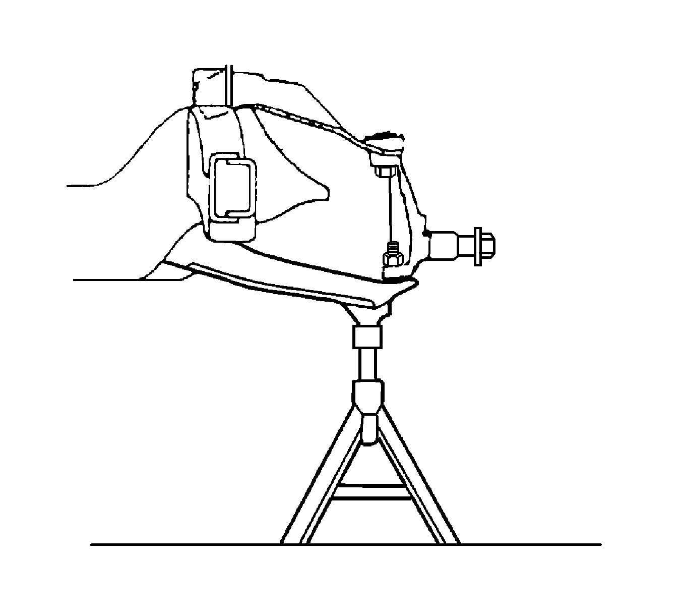
- Support the lower control arm.
- Separate the upper ball joint from the knuckle. Refer to Upper Control Arm Replacement .
- Separate the lower ball joint from the knuckle. Refer to Lower Control Arm Replacement .
- Remove the knuckle from the vehicle.


Installation Procedure
- Install the knuckle on the lower ball joint. Refer to Lower Control Arm Replacement .
- Install the upper ball joint in the knuckle. Refer to Upper Control Arm Replacement .
- Install the outer tie rod end. Refer to Steering Linkage Outer Tie Rod Replacement .
- Install the wheel bearing and hub assembly. Refer to Front Wheel Hub, Bearing, and Seal Replacement .
- Install the wheel drive shaft, if equipped. Refer to Wheel Drive Shaft Replacement .
- Remove the support from the lower control arm.
- Install the tire and wheel. Refer to Tire and Wheel Removal and Installation .
- Verify the wheel alignment. Refer to Wheel Drive Shaft Replacement .

