Removal Procedure
- Remove the master cylinder from the brake booster and support with heavy mechanic's wire or equivalent. DO NOT disconnect the hydraulic brake pipes from the master cylinder. Refer to Master Cylinder Replacement in Hydraulic Brakes.
- Remove the steering column from the vehicle. Refer to Steering Column Replacement in Steering Wheel and Column.
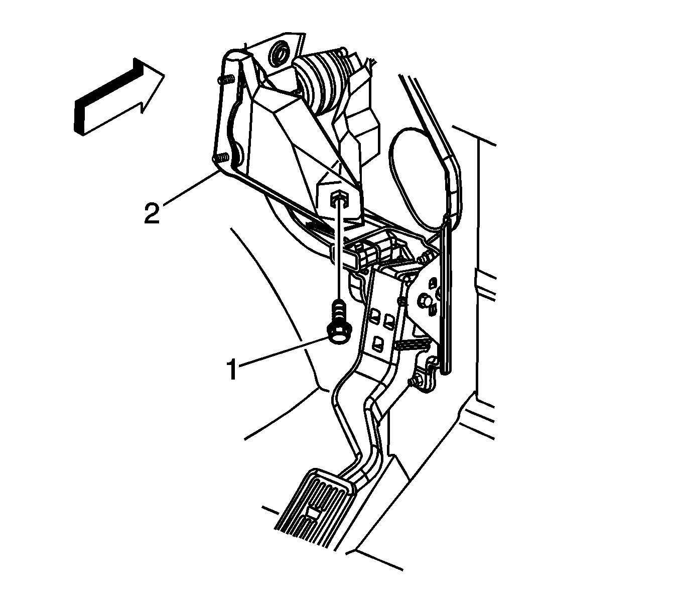
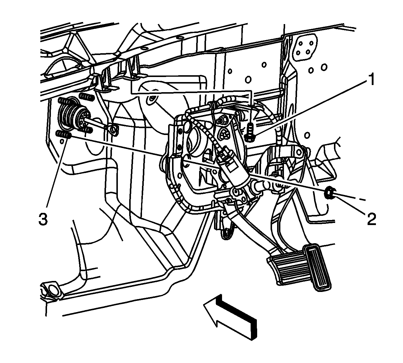
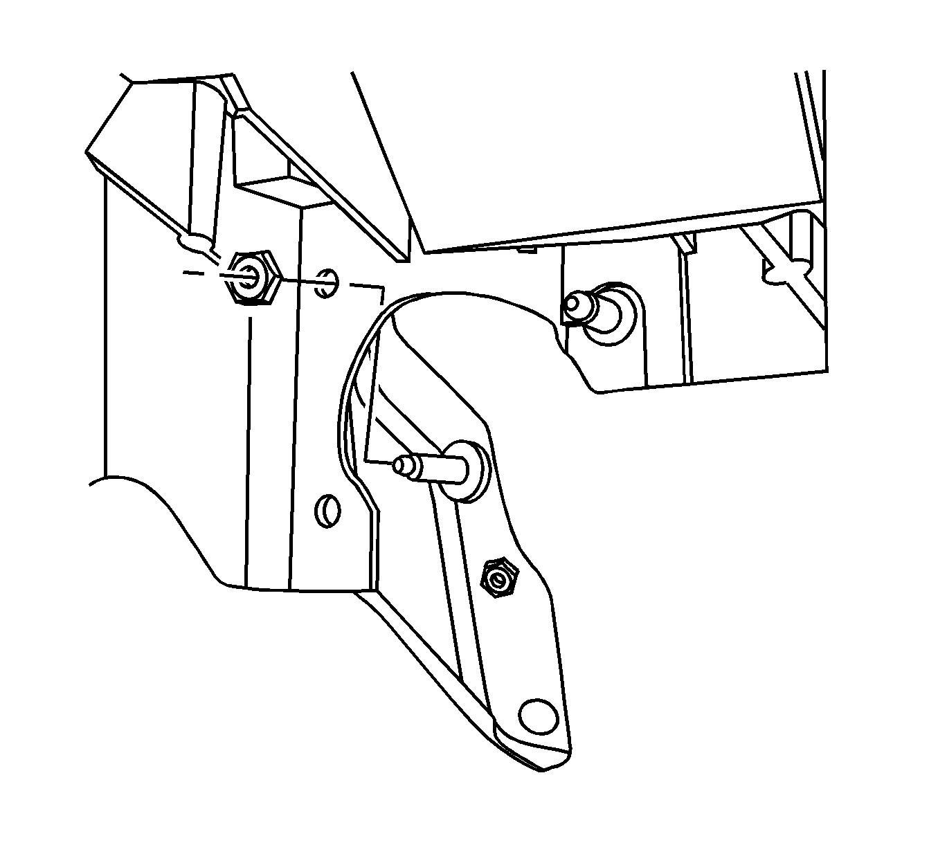
- Remove the transmission range selector cable support bolt from the instrument panel (I/P) reinforcement brace.
- Remove the upper nut from the I/P reinforcement brace at the I/P.
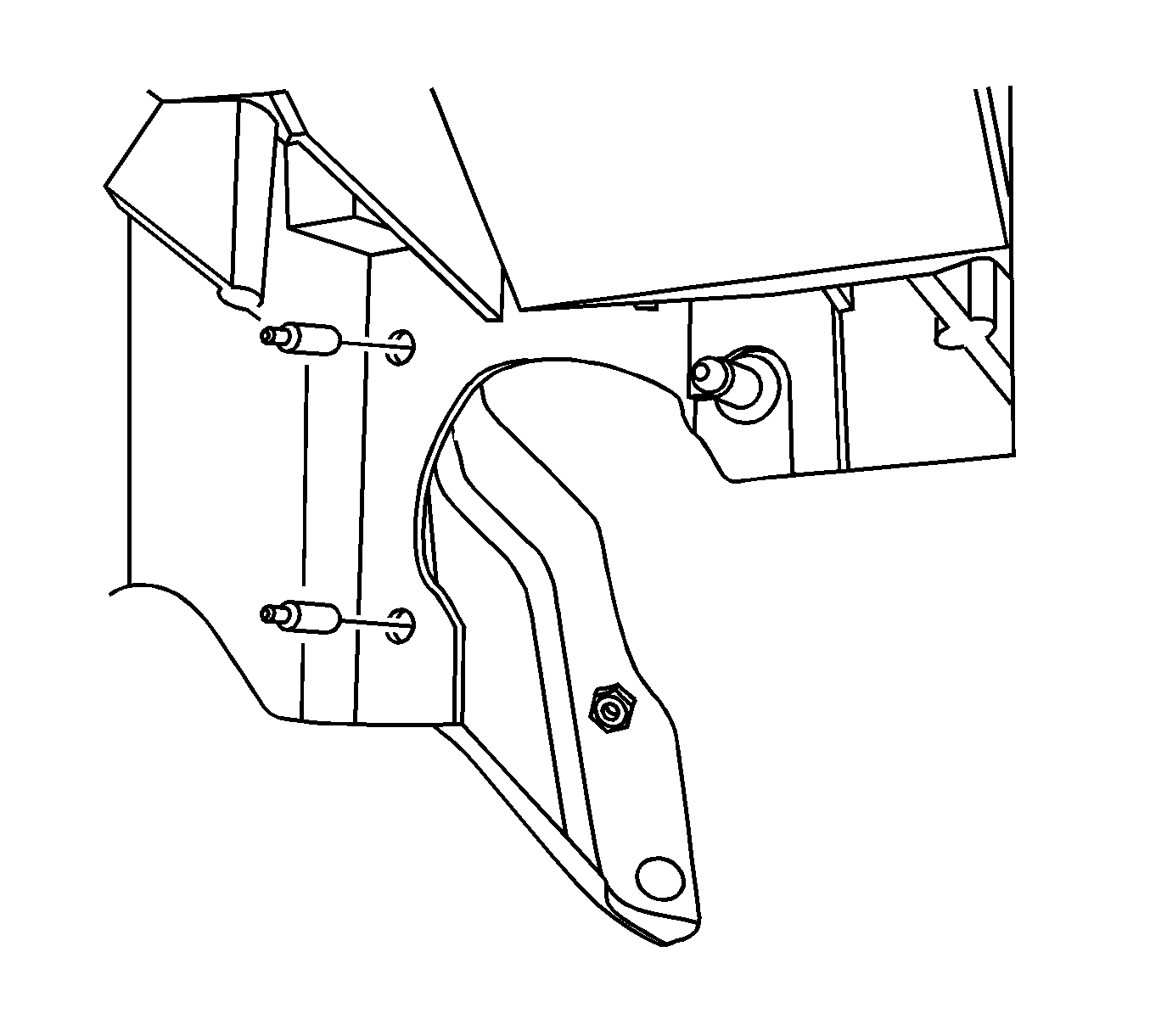
- Cut off the I/P reinforcement brace studs close to the I/P carrier. A replacement bracket, studs, and nuts are obtained in the service kit.
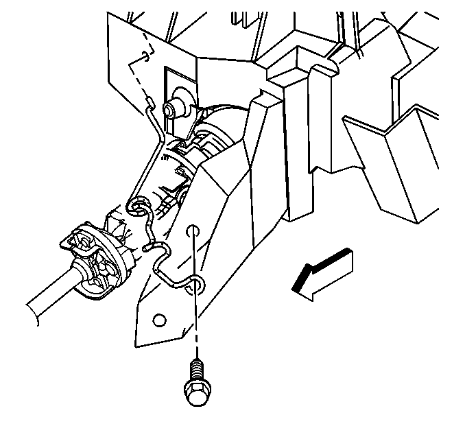
- Remove the lower I/P reinforcement brace bolt (1) from the electronic adjustable pedal (EAP) bracket.
- Remove the I/P reinforcement brace.
- Disconnect the electrical connectors from the following components:
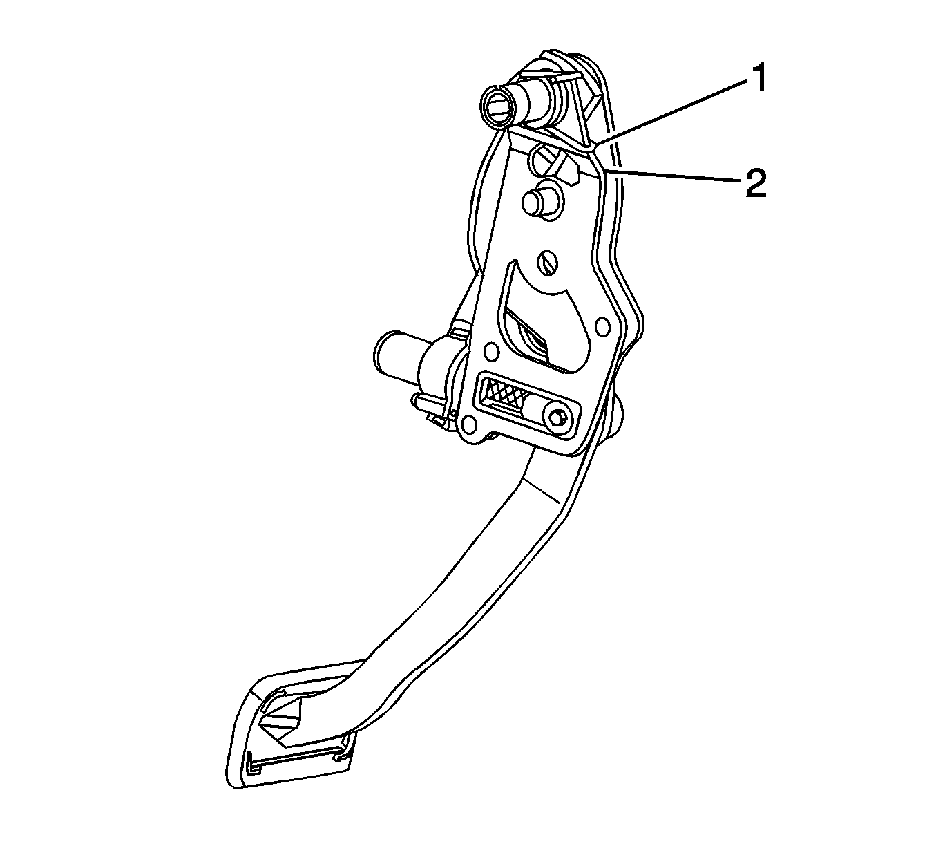
- Remove the pushrod retaining clip (3) from the brake pedal pin (1).
- Remove the brake pedal pushrod (2) and the stop lamp switch (4) from the brake pedal.
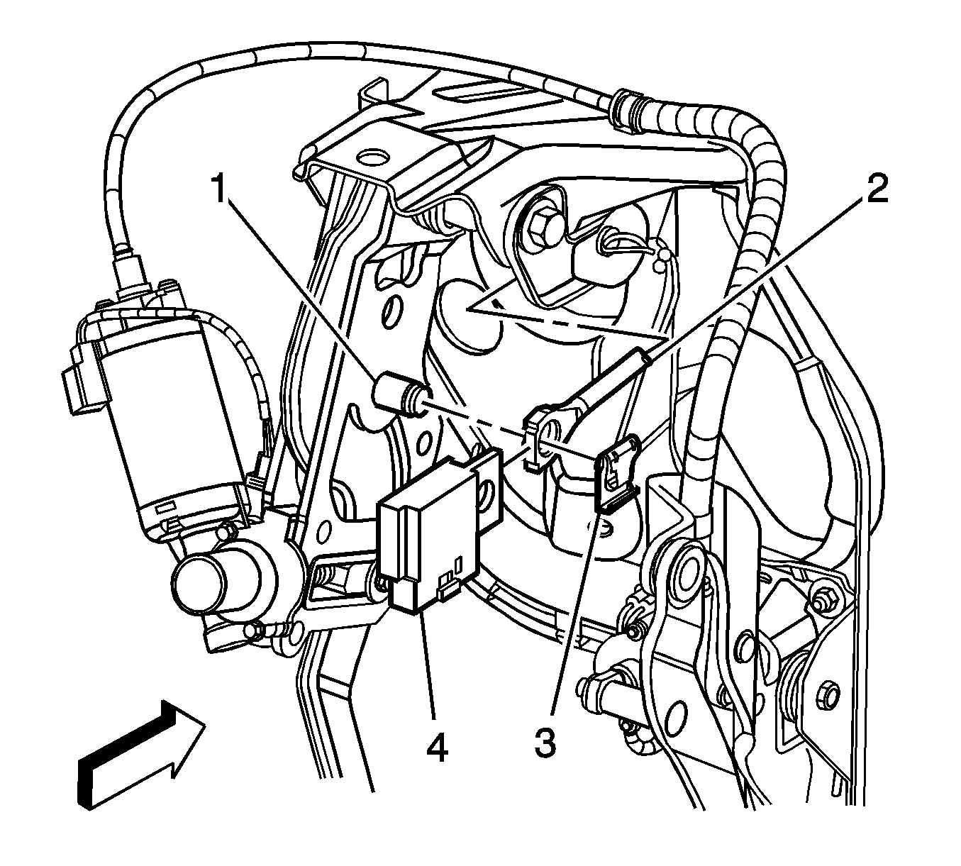
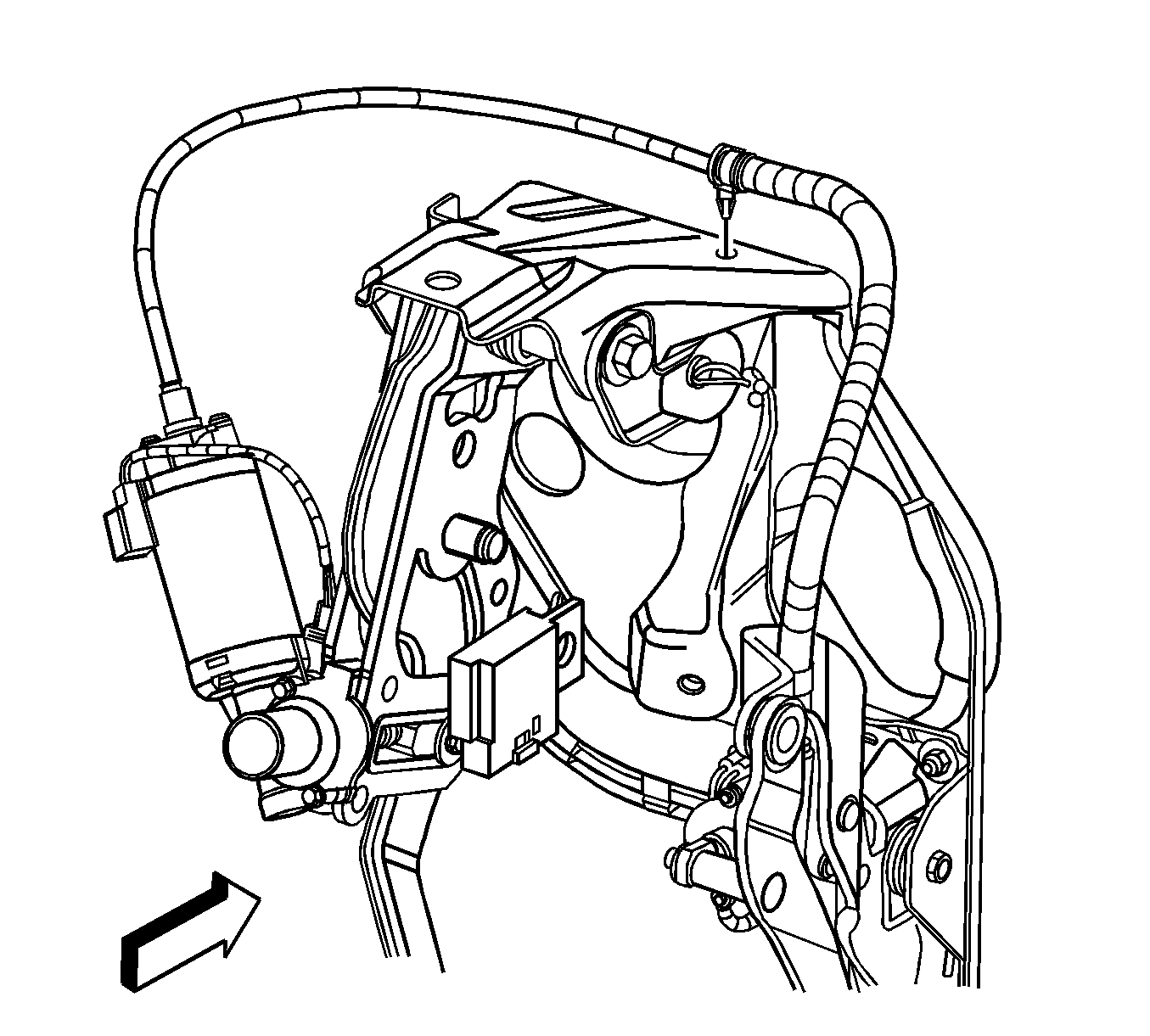
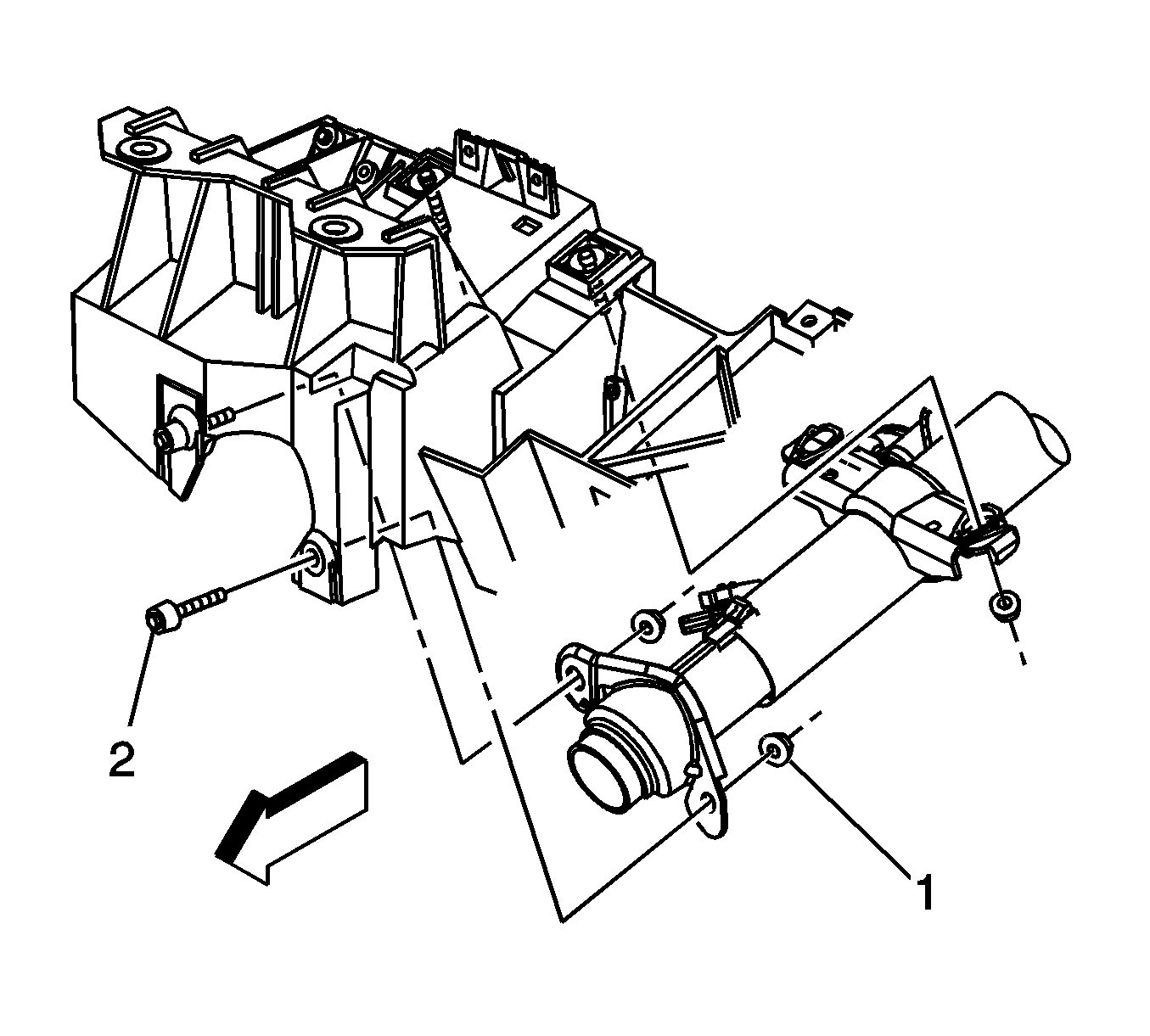
- Remove the EAP bracket nuts (2) from the studs (3) at the bulkhead.
- Remove the top EAP bracket bolt (1).
- Move the brake booster forward until the studs are removed from the mounting holes.
- Remove the EAP assembly from the vehicle.
- Remove the cable retaining clip on the top of the bracket.
- Adjust the accelerator pedal to the fully forward position using the following procedure.
- Remove the adjustable pedal cable from the accelerator pedal:
- Remove the nut from the brake pedal pivot bolt.
- Remove the brake pedal pivot bolt.
- Remove the brake pedal and return spring assembly from the bracket.
Notice: Avoid damaging the surrounding components while cutting.
| • | The adjustable pedals motor assembly |
| • | The memory sensor connector, if equipped |
| • | The pedal position sensor |
| • | The accelerator wiring harness connector |
Important: Accurate measurement and adjustment of the following step is critical to ensure the proper stepover distance between the brake and accelerator pedals.
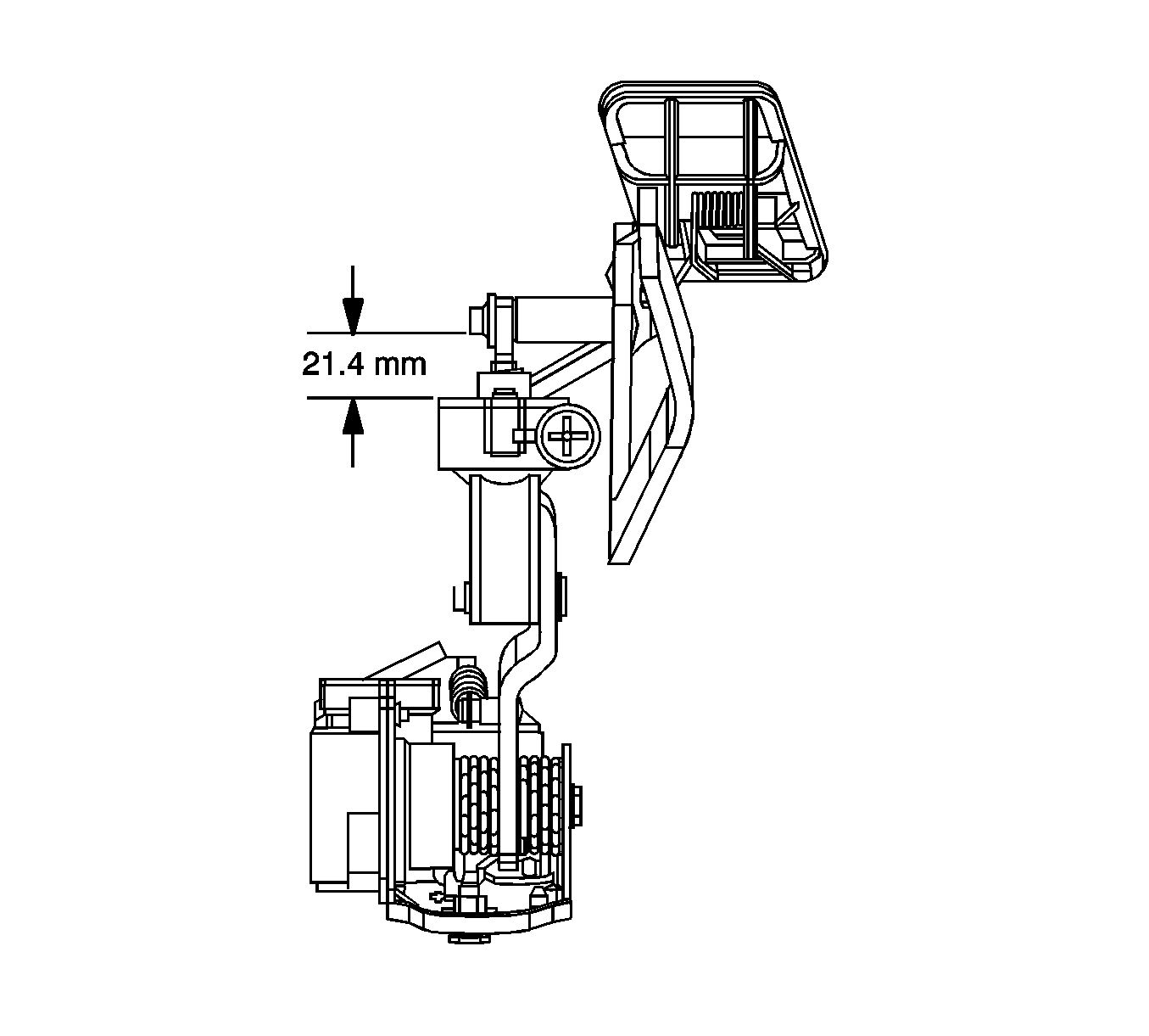
| 16.1. | Remove the screws from cable housing at the top of the adjustable pedal motor. |
| 16.2. | Twist the cable housing to unlock the cable from the motor. |
| 16.3. | Remove the cable from the adjustable pedal motor. |
| 16.4. | Attach a drill motor or equivalent to the adjustable pedal cable. |
| 16.5. | Spin the cable until there is a distance of 21.4 mm (0.84 in) from the accelerator transmission assembly cap to the small outer diameter of the adjuster pin. |
| 17.1. | Twist the cable housing to unlock the cable from the accelerator pedal. |
| 17.2. | Compress the secondary locking tabs located below the housing locking tabs and pull the cable from the accelerator pedal assembly. |
Important: Note the position of the brake pedal return spring (1).
Installation Procedure
- Install the brake pedal and return spring assembly to the bracket.
- Install the brake pedal pivot bolt.
- Install the nut to the brake pedal pivot bolt.
- Hook the return spring (1) to the backside of the brake pedal assembly (2).
- Install the adjustable pedal cable to the accelerator pedal:
- Install the cable retaining clip to the top of the bracket.
- Install the EAP assembly to the vehicle.
- Install the brake booster to its mounting position.
- Install the EAP bracket nuts (2) to the studs (3) at the bulkhead.
- Install the top EAP bracket bolt (1).
- Install the brake pedal pushrod (2) and the stop lamp switch (4) to the brake pedal.
- Install the pushrod retaining clip (3) to the brake pedal pin (1).
- Connect the electrical connectors to the following components:
- Position the replacement I/P reinforcement brace and install the upper and lower bolts to maintain the position of the brace. The lower bolt may be removed after the brace is in position.
- Install the upper I/P reinforcement brace nut to the bolt.
- Install the lower I/P reinforcement brace bolt (1) to the EAP bracket.
- Install the transmission range selector cable support bolt to the I/P reinforcement brace.
- Install the steering column to the vehicle. Refer to Steering Column Replacement in Steering Wheel and Column.
- Install the master cylinder to the brake booster. Refer to Master Cylinder Replacement in Hydraulic Brakes.
- Verify the operation of the adjustable pedals.
Notice: Refer to Fastener Notice in the Preface section.
Tighten
Tighten the nut to 30 N·m (22 lb ft).
Important: The adjustable pedals cable assembly must be installed in its original position and fastened with cable retaining clip to the top of the bracket. Make sure the cable is not twisted or binding.
| 5.1. | Insert the adjustable cable into the accelerator pedal assembly until it is secured by the secondary locking tabs. |
| 5.2. | Install and twist the cable housing to secure to the accelerator pedal assembly. |
Important: Tighten the EAP bracket nuts (2) before tightening the top EAP bracket bolt (1).
Tighten
Tighten the nuts to 25 N·m (18 lb ft).
Tighten
Tighten the bolt to 25 N·m (18 lb ft).
| • | The adjustable pedals motor assembly |
| • | The memory sensor connector, if equipped |
| • | The pedal position sensor |
| • | The accelerator wiring harness connector |
Important: Do not allow the assembly tool speed to exceed 350 RPM on fasteners with an adhesive patch.
Tighten
Tighten the nut to 22 N·m (16 lb ft).
Tighten
Tighten the bolt to 25 N·m (18 lb ft).
Tighten
Tighten the bolt to 10 N·m (89 lb in).
Install the lower I/P reinforcement brace bolt (2) after the column is in position.
