Special Tools
| • | J 21366 Converter Holding Strap |
| • | J 41798 Engine Lift Bracket |
Removal Procedure
- Disable the high voltage system. Refer to High Voltage Disabling
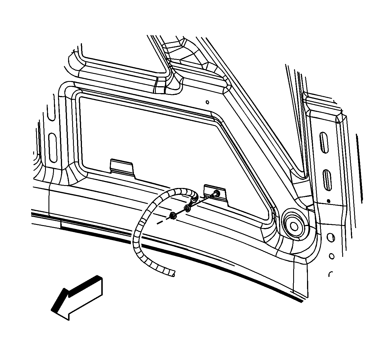
- Remove the ground strap nut at the hood stud.
- Remove the ground strap from the stud.
- Assemble 2 sets of the following: an M6 bolt, 2 each 19.05 mm (0.75 in) flat washers and an M6 nut.
- Release the retainer securing the hood strut rod to the hood strut bracket stud.
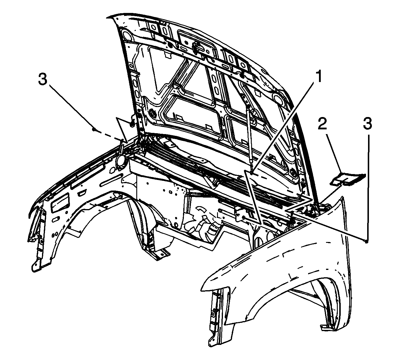
- Remove the hood strut rod (1) from the stud.
- Remove the air inlet grille end caps (2), lift the end cap up in order to disengage the retainers.
- Have an assistant support the hood.
- Remove the hood hinge bolts (3) and set aside.
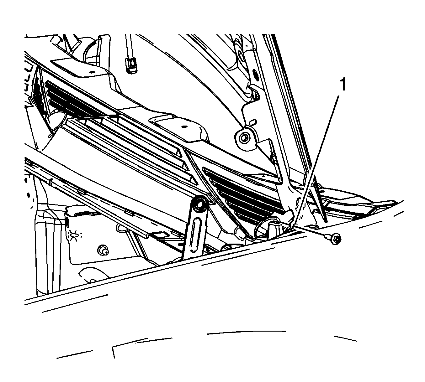
- Raise the hood until the service position notch (1) in the upper hinge is reached.
- Install the 2 sets of the M6 bolts to both the left and right side service notches and tighten finger tight.
- Lower the hood until the bolts rest against the lower hinge, tighten the bolts to secure the hood.
- The hood is now set in the service position.
- Remove the hood latch. Refer to Hood Primary and Secondary Latch Replacement.
- Remove the front end upper tie bar. Refer to Front End Upper Tie Bar Replacement.
- Remove the intake manifold. Refer to Intake Manifold Replacement.
- Drain the cooling system. Refer to Cooling System Draining and Filling.
- Disconnect the A/C lines from the A/C compressor. Refer to Discharge Hose Replacement and Suction Hose Replacement.
- Disconnect the A/C pressure sensor electrical connector.
- Disconnect the cables from the generator control module.
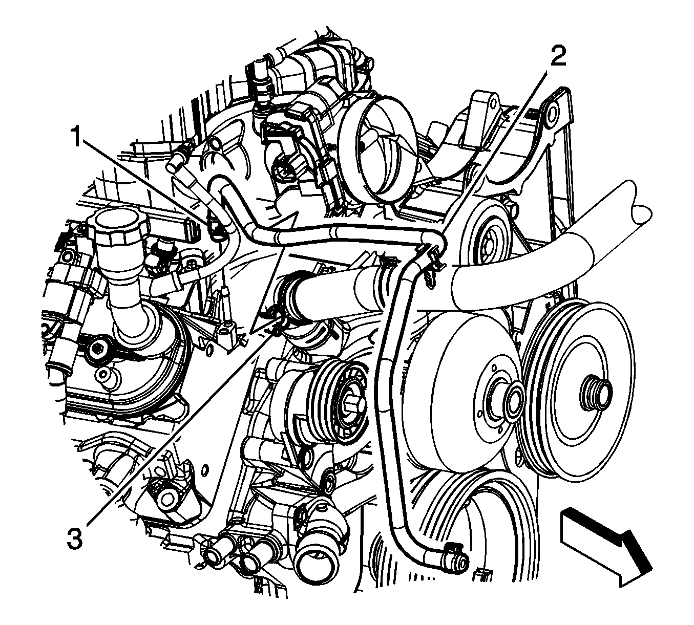
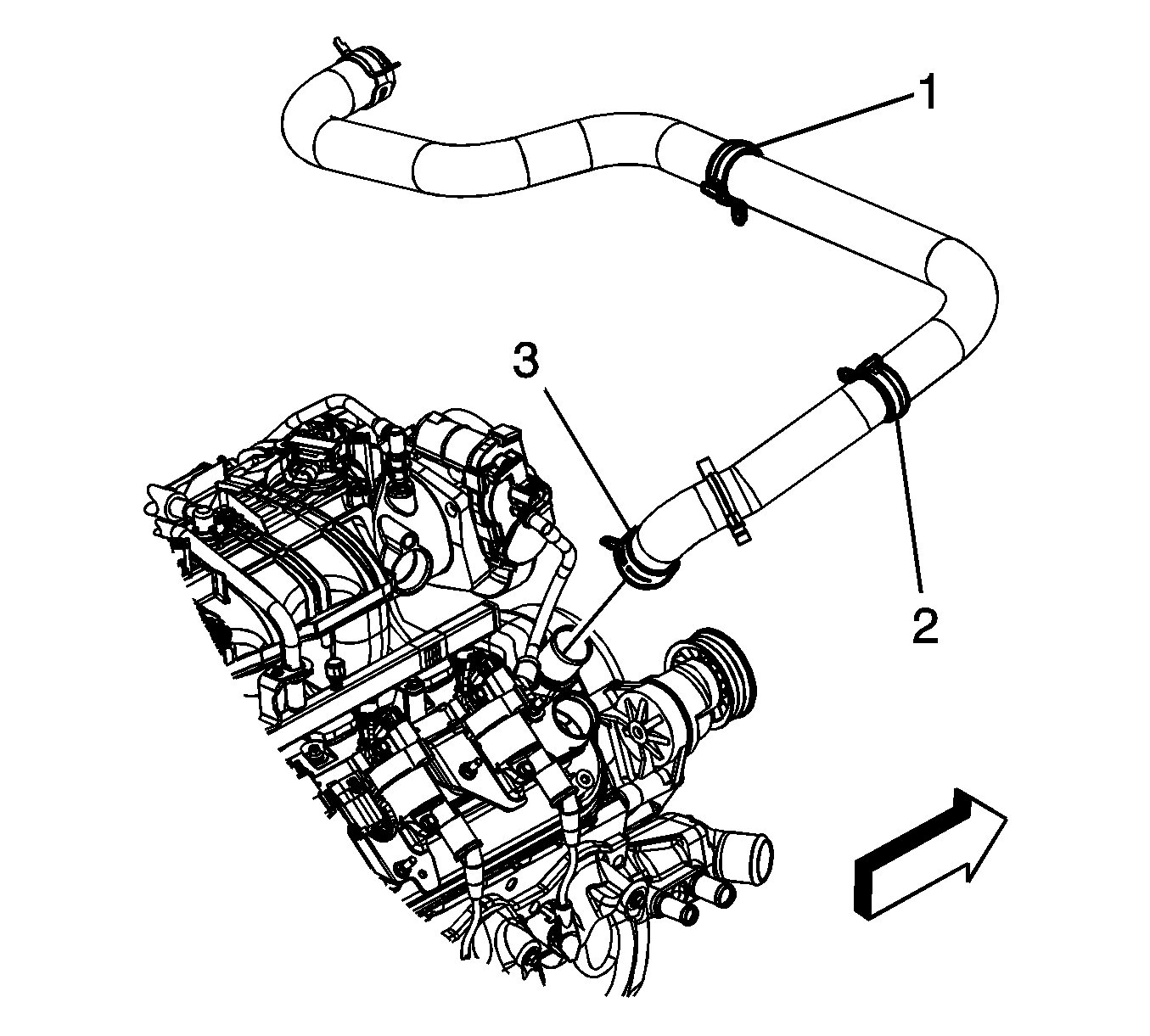
- Remove the radiator vent inlet hose (2) from the radiator inlet hose clip (3).
- Reposition the radiator vent inlet hose clamp (1) at the air bleed pipe.
- Remove the radiator vent inlet hose (2) from the air bleed pipe and reposition.
- Reposition the radiator inlet hose clamp (3) at the water pump.
- Remove the radiator inlet hose from the water pump.
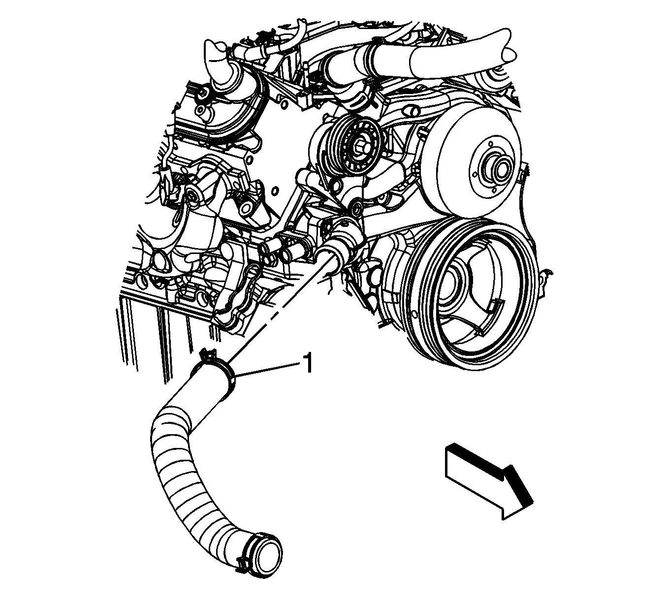
- Reposition the radiator outlet hose clamp (1) at the water pump.
- Remove the radiator outlet hose from the water pump.
- Remove the heater hoses. Refer to Heater Inlet Hose Replacement and Heater Outlet Hose Replacement.
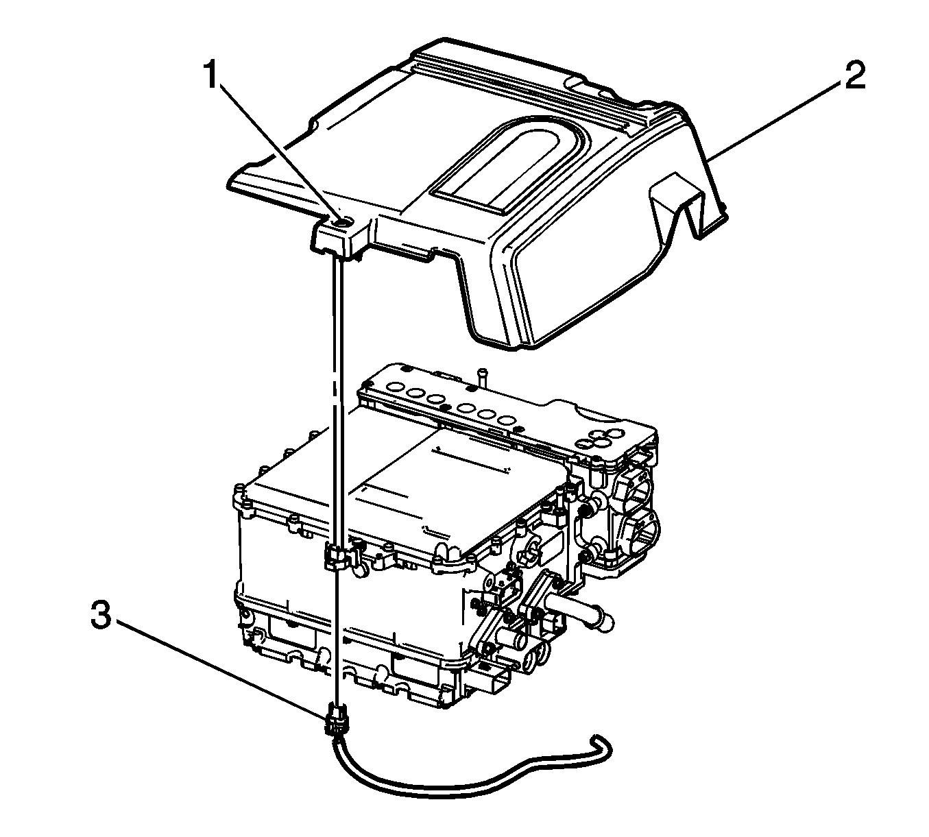
- Disconnect the engine wiring harness electrical connector (3) from the drive motor generator power inverter module cover.
- Loosen the drive motor generator power inverter module cover bolt (1).
- Remove the drive motor generator power inverter module cover (2).
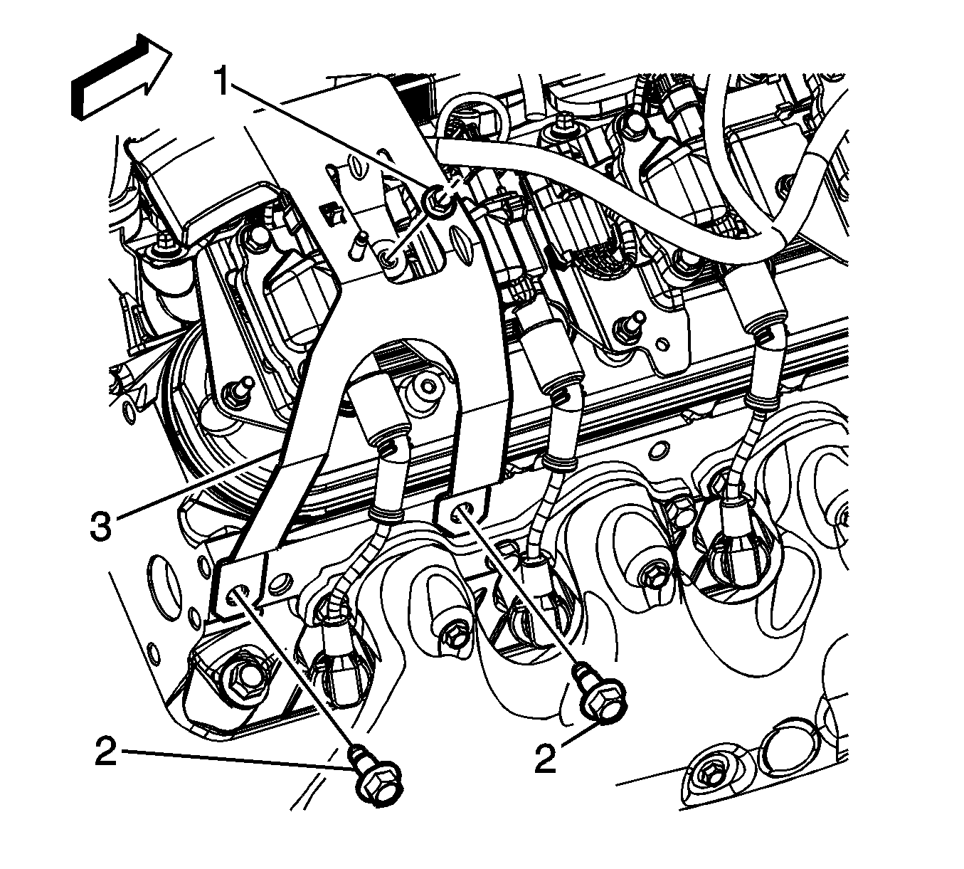
- Remove the engine bracket bolts (2).
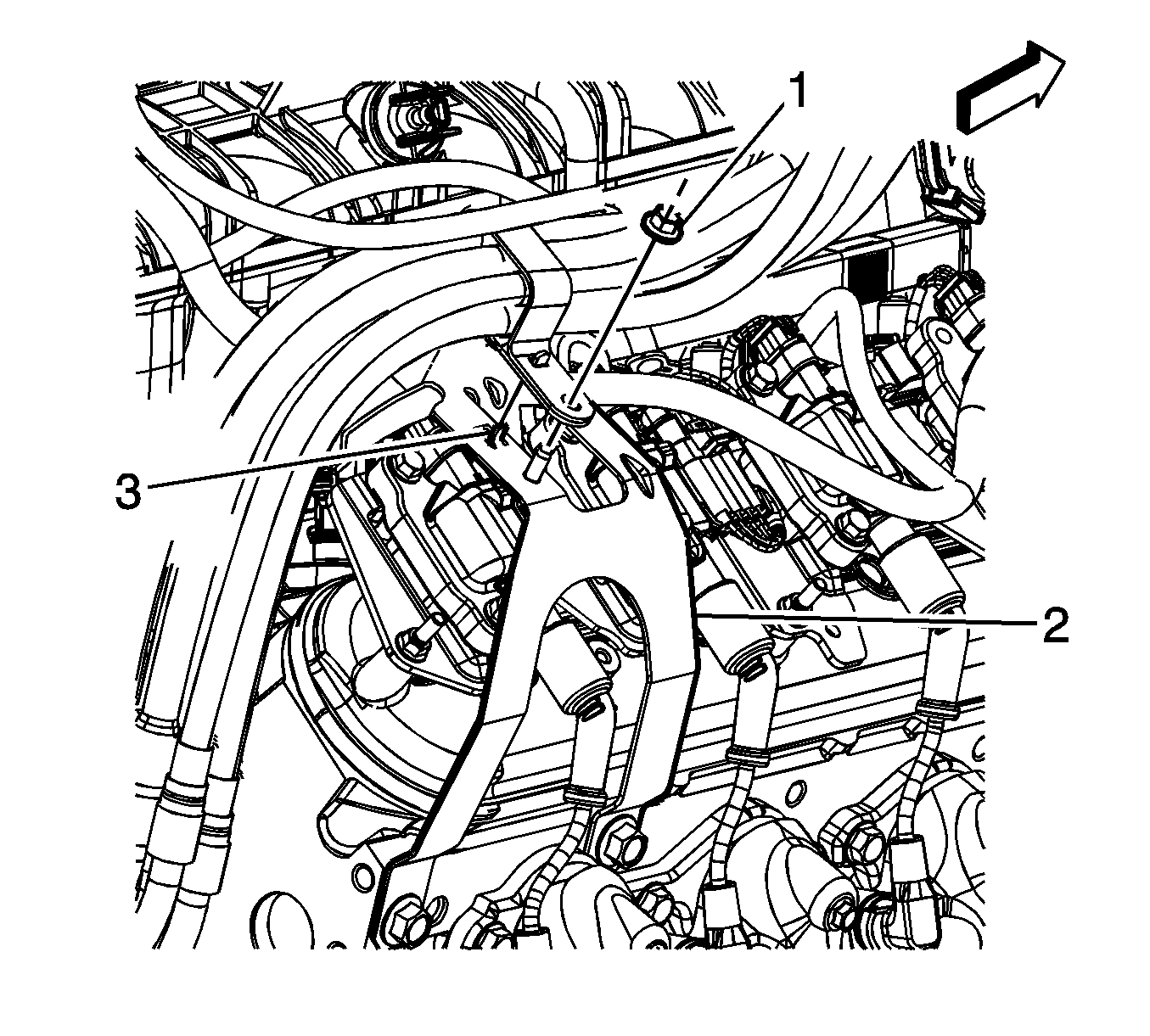
- Remove the engine bracket (3)
- Remove the generator control module 3 phase cable clip nut (1).
- Remove the generator control module 3 phase cable clip from the engine bracket (2).
- Reposition the generator control module 3 phase cables out of the way.
- Remove the right wheelhouse liner. Refer to Front Wheelhouse Liner Replacement - Right Side.
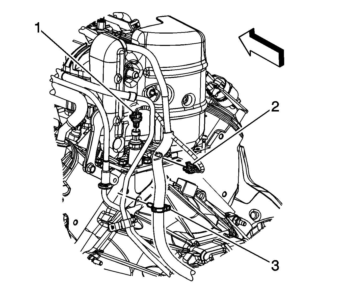
- Disconnect the engine harness electrical connector (1) from the oil pressure sensor.
- Disconnect the engine harness electrical connector (2) from the lifter oil manifold.
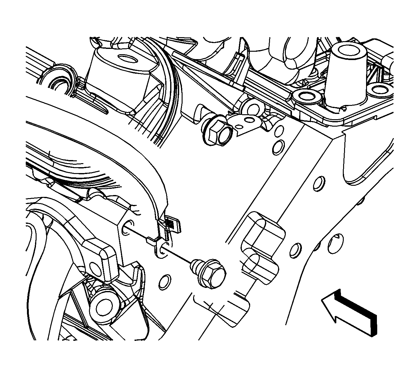
- Remove the engine ground strap bolt from the rear of the left cylinder head and cowl and reposition.
- Remove the engine ground wire from the right cylinder head.
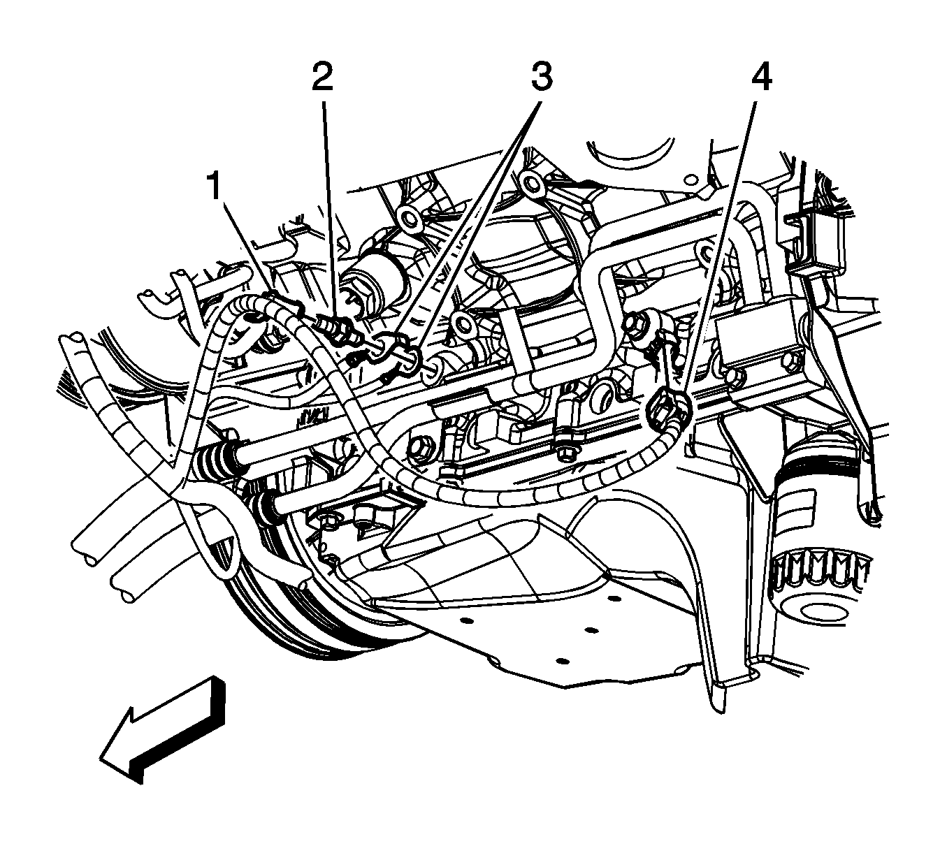
- Remove the engine harness clip (1) from the ground stud.
- Remove the engine harness ground stud (2) from the engine block.
- Remove the engine harness grounds (3) from the engine block.
- Disconnect the engine harness electrical connector (4) from the knock sensor.
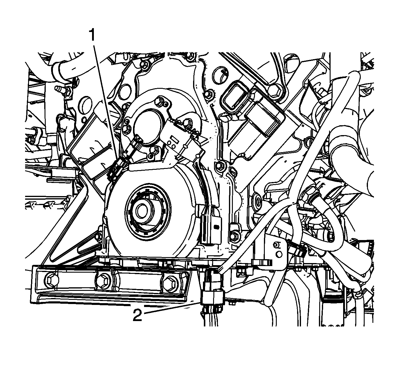
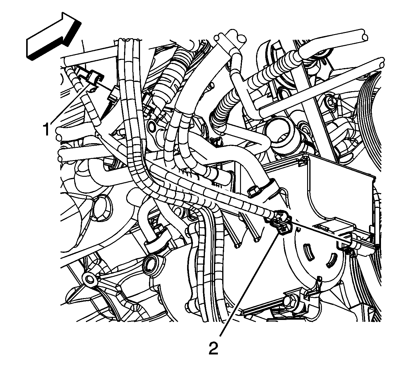
- Disconnect the engine harness electrical connector (1) from the camshaft position (CMP) sensor wire harness.
- Disconnect the auxiliary heater water pump electrical connector (1).
- Disconnect the engine harness electrical connector (2) from the A/C refrigerant pressure sensor.
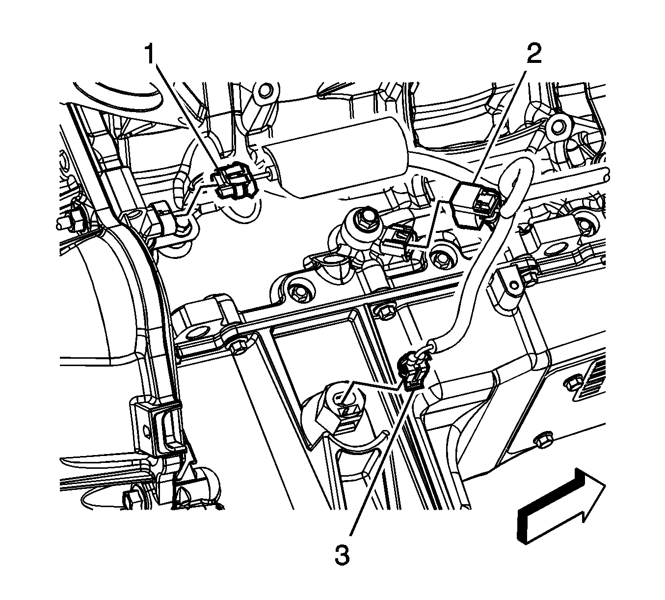
- Disconnect the engine harness electrical connector (1) from the crankshaft position (CKP) sensor.
- Disconnect the engine harness electrical connector (2) from the knock sensor.
- Disconnect the engine harness electrical connector (3) from the oil level sensor.
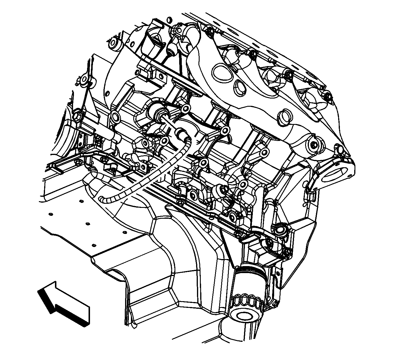
- Disconnect the coolant heater cord from the coolant heater, if equipped.
- Lower the vehicle.
- Remove the ignition coil, as required for proper fit of the J 41798 . Before lifting the engine, refer to Ignition Coil Replacement.
- Remove the 3 phase cable bracket from the right cylinder head.
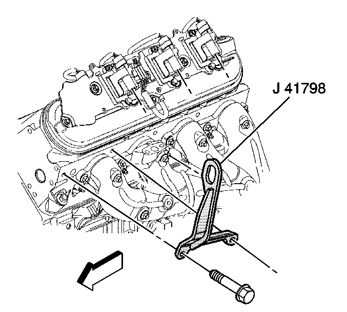
- Install the J 41798 to left and right cylinder heads.
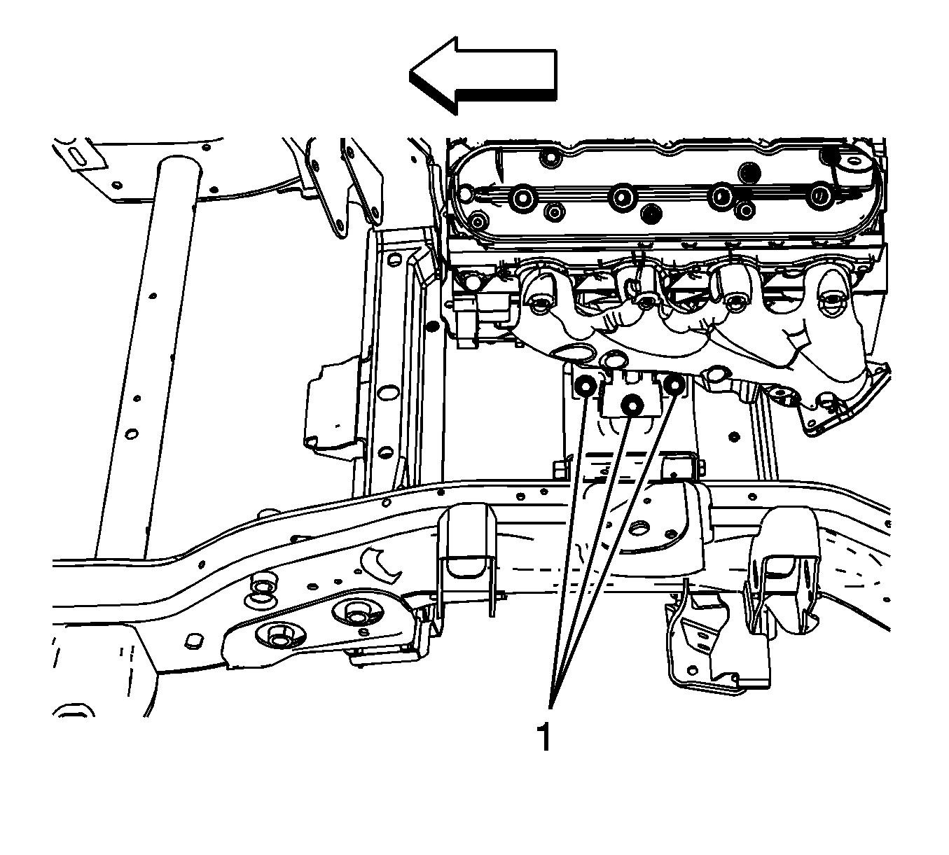
- Remove the left and right engine mount to frame bolts (1).
- Raise the vehicle.
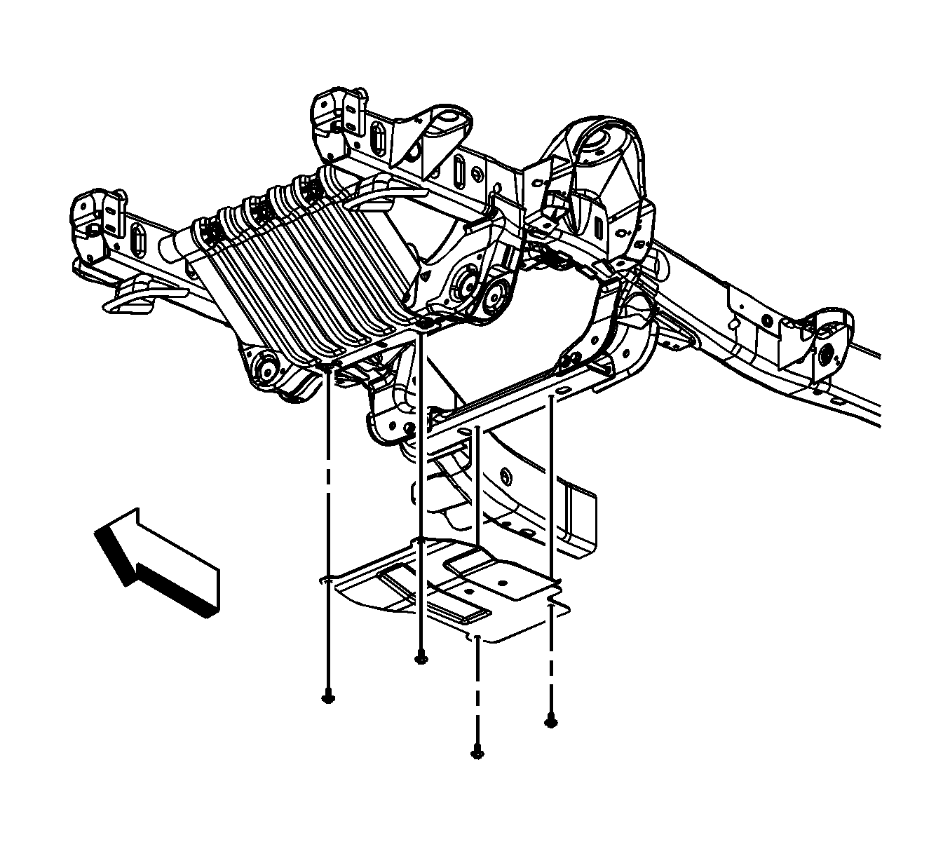
- Remove the oil pan skid plate bolts and plate, if equipped.
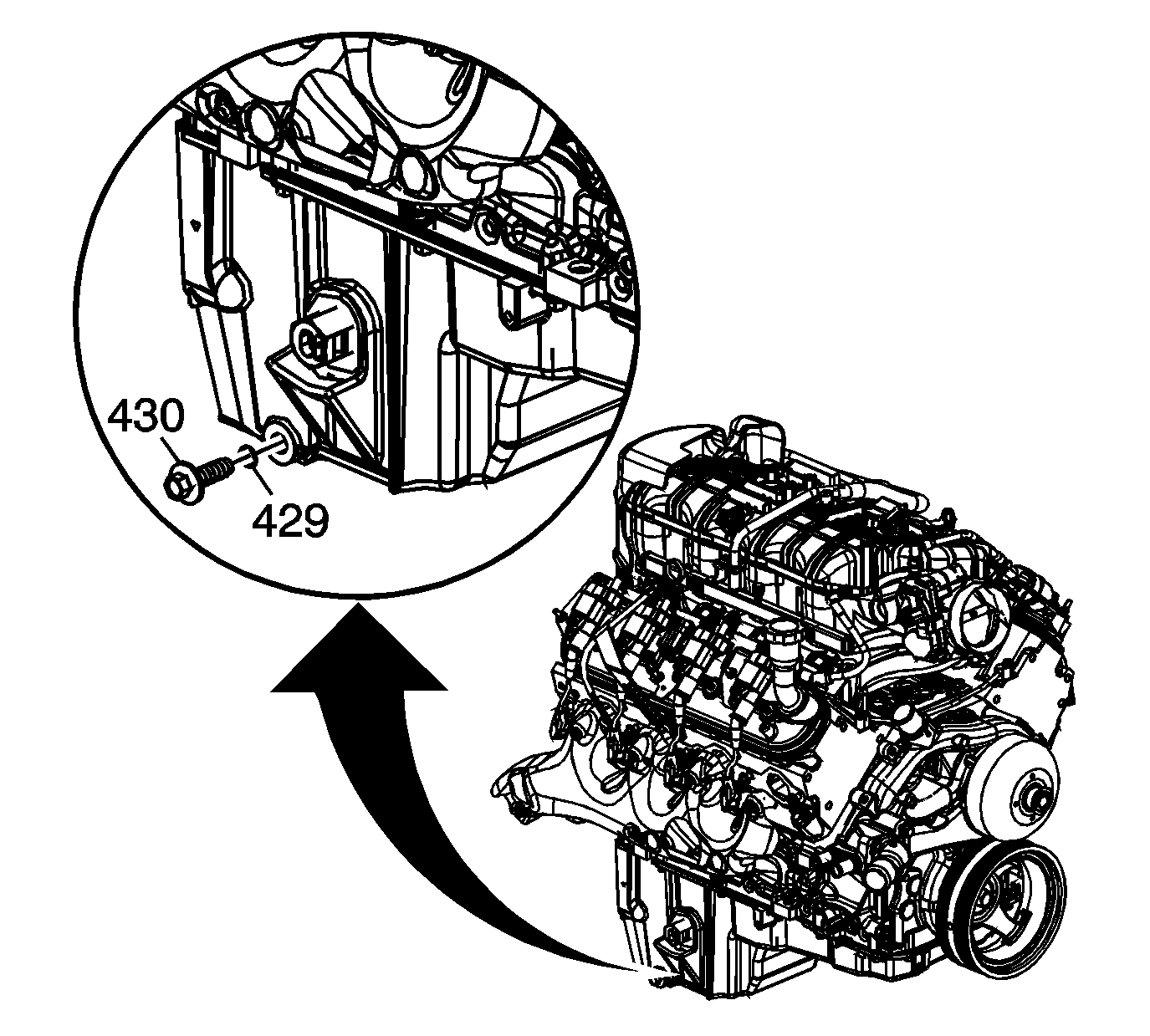
- Place a suitable drain pan under the oil pan drain plug.
- Remove the oil pan drain plug (430).
- Allow the oil to drain completely.
- Reinstall and tighten the oil pan drain plug.
- Remove the catalytic converter. Refer to Catalytic Converter Replacement.
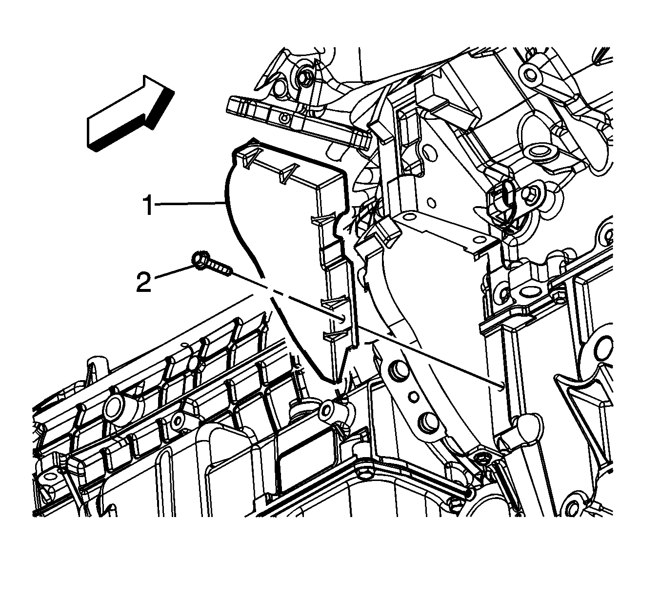
- Remove the right flex plate inspection cover bolt (2).
- Remove the right flex plate inspection cover (1).
- With the aid of an assistant, hold the crank pulley, then remove the flywheel to torque dampener bolts.
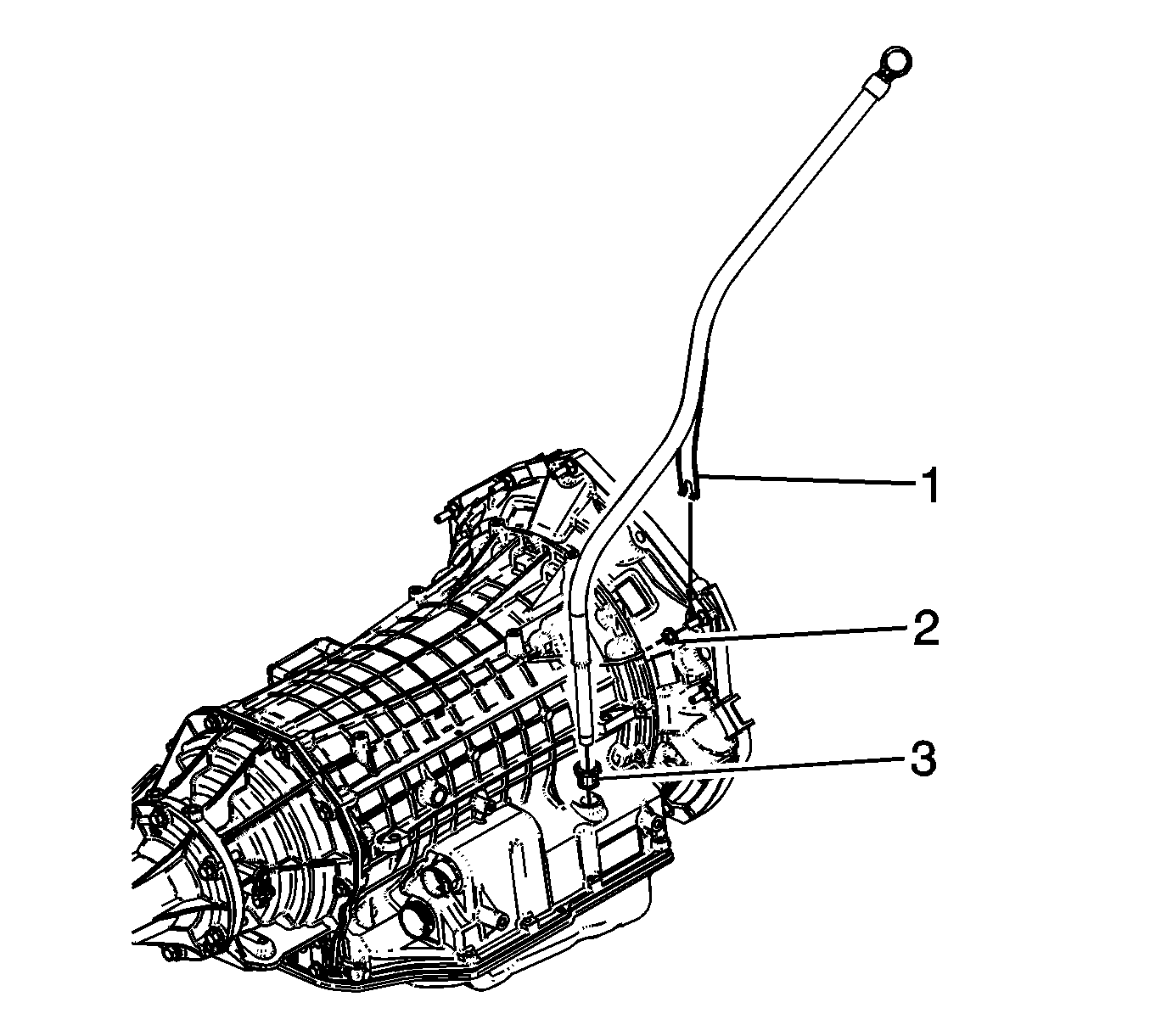
- Remove the fluid filler tube retaining nut (2) and reposition fill tube aside as necessary.
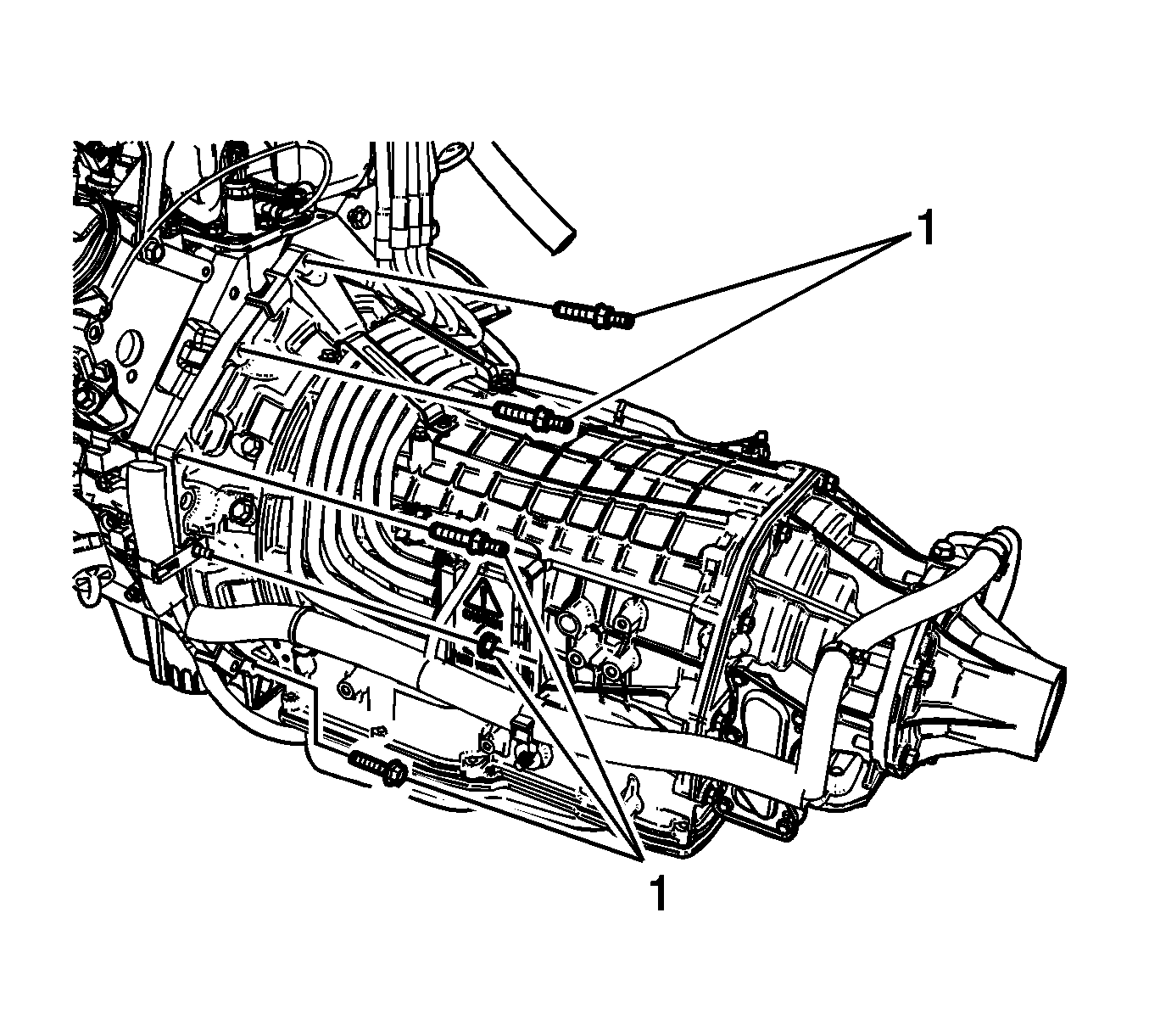
- Remove the transmission bolts/studs (1).
- Lower the vehicle.
- Remove the fuel/evaporative emission (EVAP) pipe bracket nut from the transmission stud.
- Remove the fuel/EVAP pipe bracket from the stud. Reposition the bracket out of the way.
- Position and install an engine hoist to the J 41798 .
- Install a floor jack under the transmission for support.
- Remove the engine from the vehicle.
- Install the J 21366 .
- Position and install the engine onto an engine stand.
- Remove the engine hoist. from the J 41798 .
- Remove the J 41798 .
Danger: Always perform the High Voltage Disabling procedure prior to servicing any High Voltage component or connection. Personal Protection Equipment (PPE) and proper procedures must be followed.
The High Voltage Disabling procedure will perform the following tasks:| • | Identify how to disable high voltage. |
| • | Identify how to test for the presence of high voltage. |
| • | Identify condition under which high voltage is always present and personal protection equipment (PPE) and proper procedures must be followed. |
Important: There is a positive stop which limits the hood from being opened too far.
Notice: Refer to Fastener Notice in the Preface section.
Tighten
Tighten the bolts to 20 N·m (15 lb ft).
Tighten
| • | Tighten the M8 engine lift bracket bolts to 25 N·m (18 lb ft). |
| • | Tighten the M10 engine lift bracket bolts to 50 N·m (37 lb ft). |
Tighten
Tighten the drain plug to 25 N·m (18 lb ft).
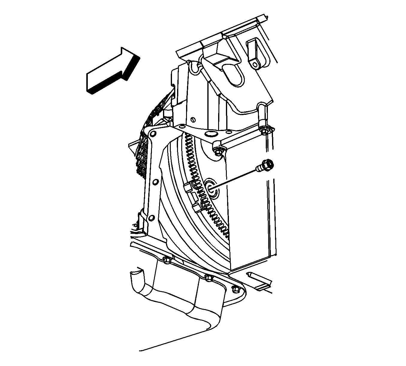
Important: Rotate engine clockwise only.

Installation Procedure
- Install the J 41798 .
- Position and install the engine hoist to the J 41798 .
- Remove the engine from the engine stand.
- Remove the J 21366 .
- Install the engine to the vehicle.
- Align and install the engine to the transmission. Raise or lower the transmission as required using the floor jack.
- Once aligned and mated together completely lower and remove the engine hoist.
- Install the left and right engine mount to frame bolts (1).
- Remove the floor jack from under the transmission.
- Raise the vehicle.
- Install the transmission bolts/studs (1).
- Install the fuel/EVAP pipe bracket to the stud.
- Install the fuel/evaporative emission (EVAP) pipe bracket nut to the transmission stud.
- Install the fluid filler tube bracket to the transmission.
- Install the fluid filler tube retaining nut (2).
- Align the torque dampener bolt holes to the flywheel bolt holes.
- With the aid of an assistant, hold the crank pulley, then install the flywheel to torque dampener bolts.
- Install the right flex plate inspection cover (1).
- Install the right flex plate inspection cover bolt (2).
- Install the catalytic converter. Refer to Catalytic Converter Replacement.
- Lower the vehicle.
- Remove the J 41798 .
- Install the 3 phase cable bracket to the right cylinder head.
- Install the ignition coil(s) and spark plug wire(s), as required. Refer to Ignition Coil Replacement.
- Raise the vehicle.
- Connect the coolant heater cord to the coolant heater, if equipped.
- Connect the engine harness electrical connector (1) to the CKP sensor.
- Connect the engine harness electrical connector (2) to the knock sensor.
- Connect the engine harness electrical connector (3) to the oil level sensor.
- Connect the engine harness electrical connector (2) to the A/C refrigerant pressure sensor.
- Connect the auxiliary heater water pump electrical connector (1).
- Connect the engine harness electrical connector (1) to the CMP sensor wire harness.
- Connect the engine harness electrical connector (4) to the knock sensor.
- Position the engine harness grounds (3) to the engine block.
- Install the engine harness ground stud (2) to the engine block.
- Install the engine harness clip (1) to the ground stud.
- Lower the vehicle.
- Position the engine ground wire to the right cylinder head.
- Install the engine harness stud (1) to the right cylinder head.
- Position the engine ground strap to the cylinder head and cowl.
- Install the engine ground strap bolt to the rear of the left cylinder head and cowl.
- Install the engine bracket (3) to the ignition coil bracket stud and install nut (1).
- Raise the vehicle half way.
- Working through the wheel opening, install the engine bracket bolts (2).
- Install the right wheelhouse liner. Refer to Front Wheelhouse Liner Replacement - Right Side.
- Position the generator control module 3 phase cables to the bracket channel.
- Install the generator control module 3 phase cable clip to the tab (3) on the engine bracket (2).
- Install the generator control module 3 phase cable clip nut (1).
- Connect the engine harness electrical connector (1) to the oil pressure sensor.
- Connect the engine harness electrical connector (2) to the lifter oil manifold.
- Install the heater hoses. Refer to Heater Inlet Hose Replacement and Heater Outlet Hose Replacement.
- Install the radiator outlet hose to the water pump.
- Position the radiator outlet hose clamp (1) at the water pump.
- Install the radiator inlet hose to the water pump.
- Position the radiator inlet hose clamp (3) at the water pump.
- Position and install the radiator vent inlet hose (2) to the air bleed pipe.
- Position the radiator vent inlet hose clamp (1) at the air bleed pipe.
- Install the radiator vent inlet hose (2) to the radiator inlet hose clip (3).
- Position the generator battery jumper to the engine.
- Install the intake manifold. Refer to Intake Manifold Replacement.
- Connect the cables from the generator control module.
- Connect the A/C pressure sensor electrical connector.
- Connect the A/C lines from the A/C compressor. Refer to Discharge Hose Replacement and Suction Hose Replacement.
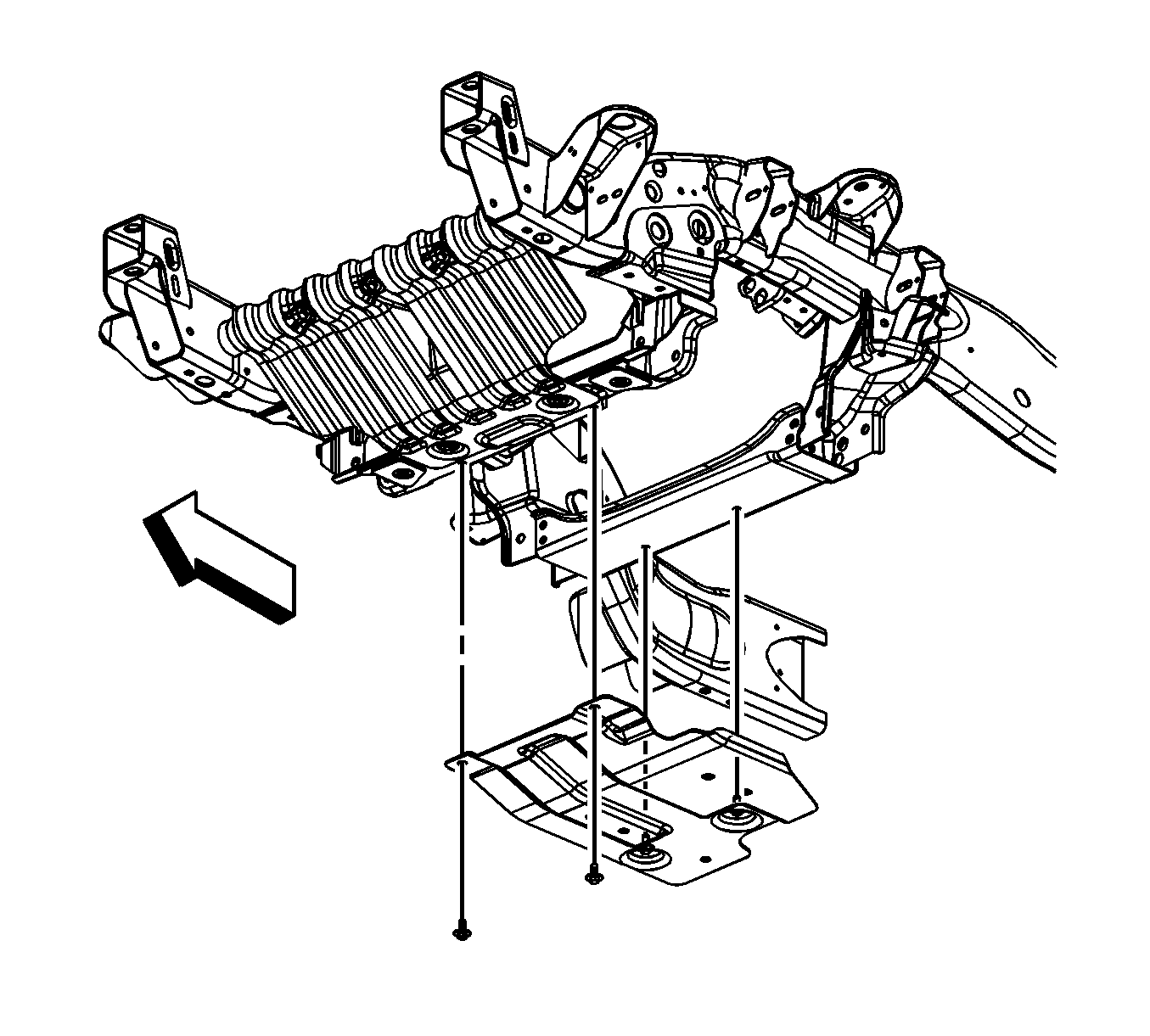
- For 2500 series vehicles, install the oil pan skid plate and bolts, if equipped.
- For 1500 series vehicles, install the oil pan skid plate and bolts, if equipped.
- Lower the vehicle.
- Install the front end upper tie bar. Refer to Front End Upper Tie Bar Replacement.
- Install the hood latch. Refer to Hood Primary and Secondary Latch Replacement.
- With the aid of the assistant raise the hood slightly until the hood hinge bolts can be removed from the service position notch (1).
- With the aid of an assistant lower the hood and install the hood hinge bolts (3) to the hood hinges.
- Install the hood strut rod (1) to the hood strut bracket stud.
- Install the air inlet grille end caps (2), push down the end cap in order to engage the retainers.
- Install the ground strap to the hood stud.
- Install the ground strap nut at the hood stud.
- Refill the cooling system. Refer to Cooling System Draining and Filling.
- Prelube the engine. Refer to Engine Prelubing.
- Enable the high voltage system. Refer to High Voltage Enabling.
- Perform the CKP system variation learn procedure. Refer to Crankshaft Position System Variation Learn.
- Use the following procedure after the engine is installed in the vehicle:
Notice: Refer to Fastener Notice in the Preface section.

Tighten
| • | Tighten the M8 engine lift bracket bolts to 25 N·m (18 lb ft). |
| • | Tighten the M10 engine lift bracket bolts to 50 N·m (37 lb ft). |

Tighten
Tighten the bolts to 65 N·m (48 lb ft) starting with the middle bolt then either side bolt.

Tighten
Tighten the bolts/studs to 50 N·m (37 lb ft).
Tighten
Tighten the nut to 18 N·m (13 lb ft).

Tighten
Tighten the nut to 18 N·m (13 lb ft).

Important: Rotate engine clockwise only.
Tighten
Tighten the bolts to 65 N·m (48 lb ft).

Tighten
Tighten the bolt to 12 N·m (106 lb in).


Tighten
Tighten the stud to 16 N·m (12 lb ft).
Tighten
Tighten the stud to 25 N·m (18 lb ft).

Tighten
Tighten the bolt to 16 N·m (12 lb ft).

Tighten
Tighten the nut to 12 N·m (106 lb in).
Tighten
Tighten the bolts to 50 N·m (37 lb ft).

Tighten
Tighten the nut to 9 N·m (80 lb in).


Tighten
Tighten the bolts to 28 N·m (21 lb ft).

Tighten
Tighten the bolts to 28 N·m (21 lb ft).

Important: There is a positive stop which limits the hood from being opened too far.

Tighten
Tighten the bolts to 25 N·m (18 lb ft).

Tighten
Tighten the nut to 9 N·m (80 lb in).
Important: After an overhaul the engine should be tested.
| 79.1. | Disable the ignition system. |
| 79.2. | Crank the engine several times. Listen for any unusual noises or evidence that parts are binding. |
| 79.3. | Enable the ignition system. |
| 79.4. | Start the engine and listen for unusual noises. |
| 79.5. | Check the vehicle oil pressure gage or light and confirm that the engine has acceptable oil pressure. |
| 79.6. | Run the engine speed at about 1,000 RPM until the engine has reached normal operating temperature. |
| 79.7. | Listen for sticking lifters or other unusual noises. |
| 79.8. | Inspect for fuel, oil and/or coolant leaks while the engine is running. |
| 79.9. | Perform a final inspection for the proper oil and coolant levels. |
