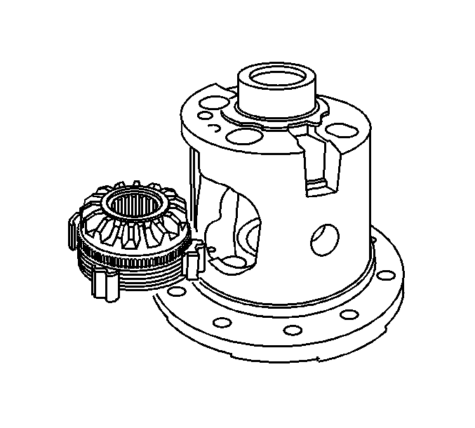
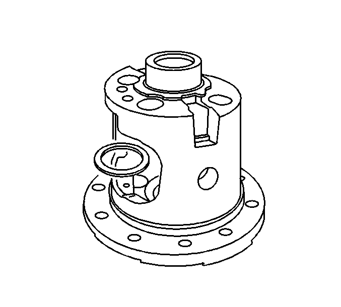
For 1990-2009 cars only
Locking Differential Disassemble 10.5 Inch Axle
- Remove the differential assembly. Refer to Differential Replacement.
- Remove the ring gear. Refer to Drive Pinion and Ring Gear Replacement.
- Remove the differential side bearings. Refer to Differential Side Bearings Replacement.
- Remove the differential case screws.
- Separate the case halves by performing the following steps:
- Remove the governor assembly.
- Remove the latching bracket assembly.
- Remove the thrust block.
- Remove the following components from the differential case:
- Mark the differential spider, the differential pinion gears and the differential pinion gears accordingly in order to re-assemble the components correctly into the differential case.
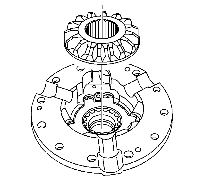
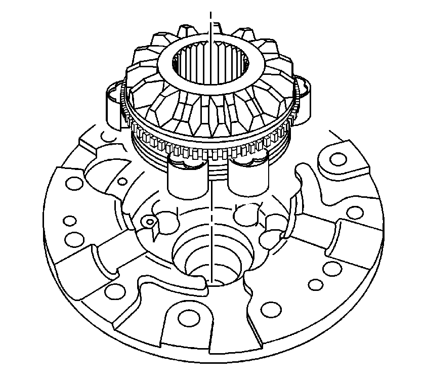
- Remove the locking differential side gear.
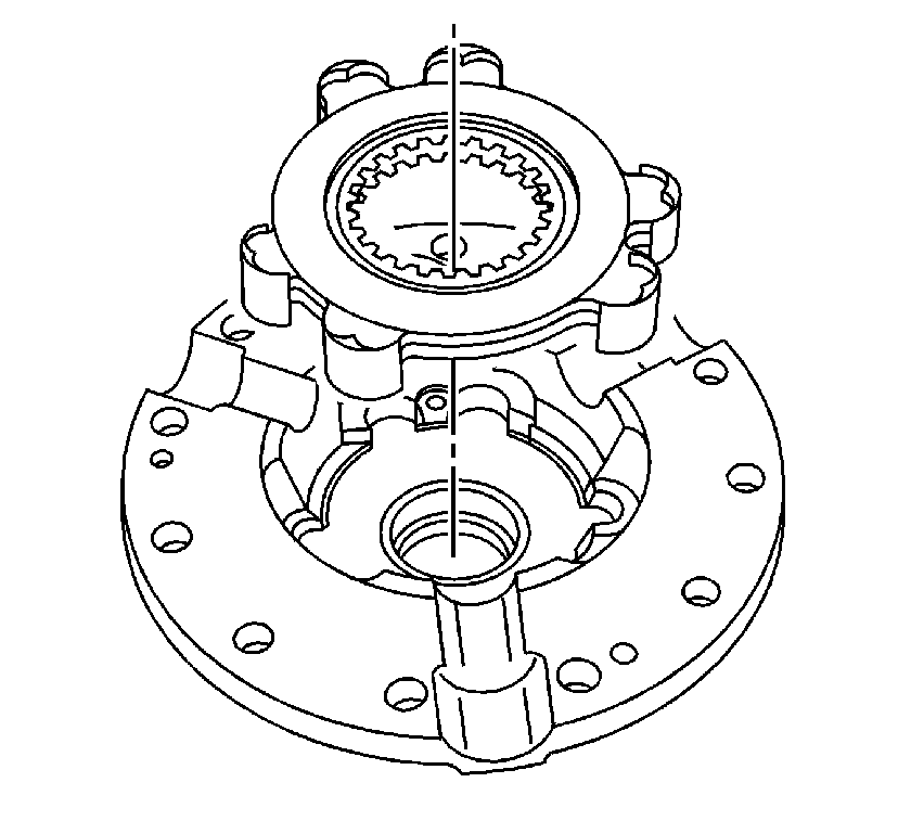
- Remove the left side clutch plates and the guide clips.
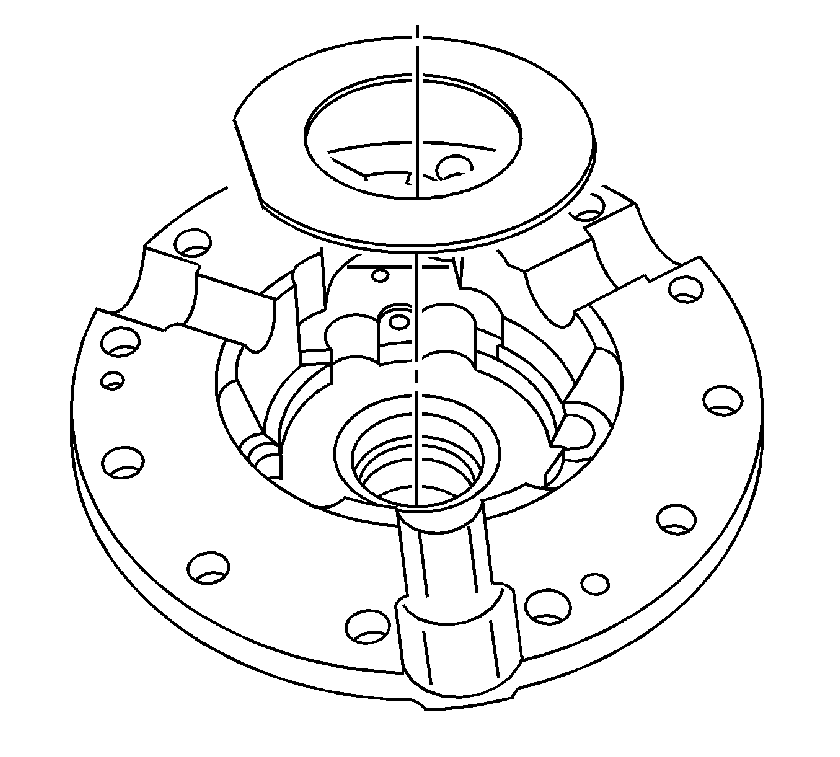
- Remove the left side gear thrust washer.
- Remove the right side cam unit and clutch plate assembly.
- Remove the right side locking differential clutch disc thrust washer.
- Disassemble the left side differential side gear and clutch disc assembly. Refer to Locking Differential Clutch Disc Assembly Disassemble.
- Disassemble the right side locking differential side gear cam unit and clutch disc assembly. Refer to Locking Differential Cam Unit Disassemble.
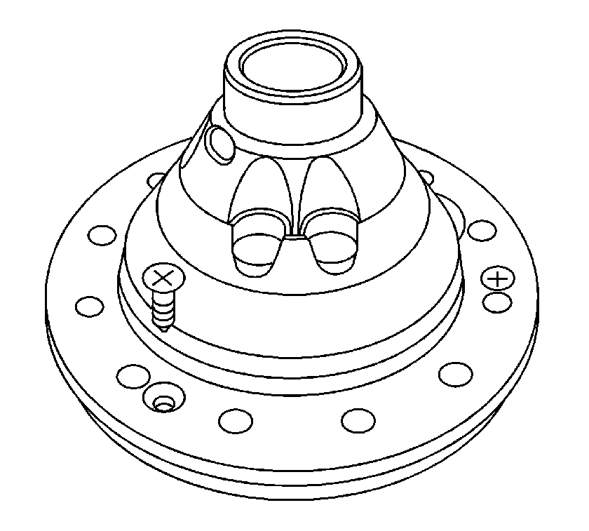
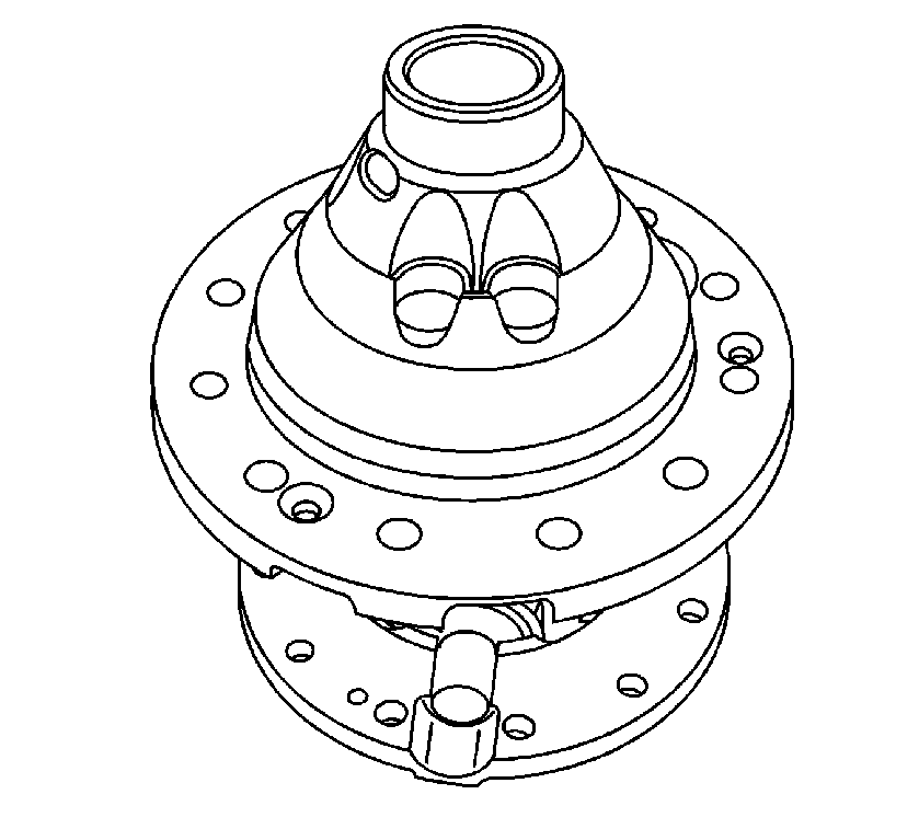
| 5.1. | Pry the case halves apart at the yoke hole location. |
| 5.2. | Hold the locking differential cam, side gear and clutch plate assembly in the right side case half. |
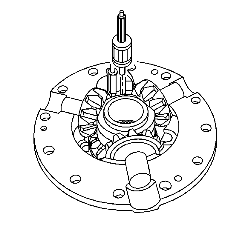
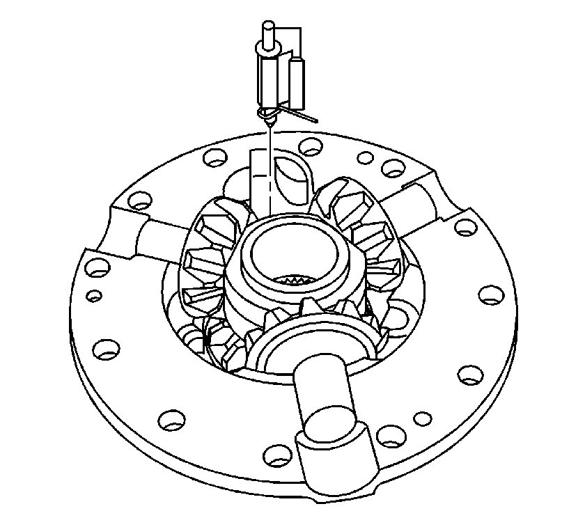
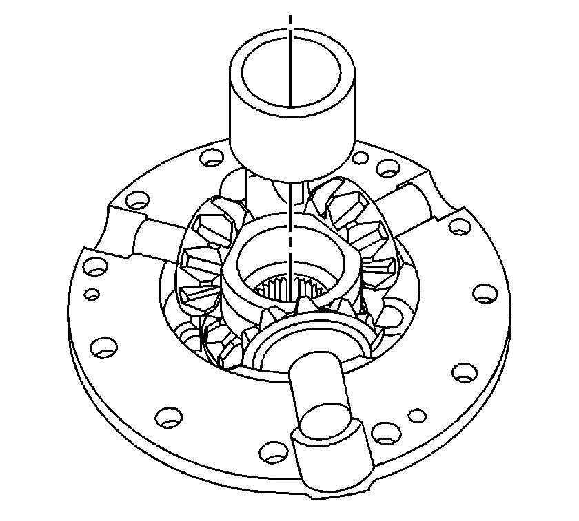
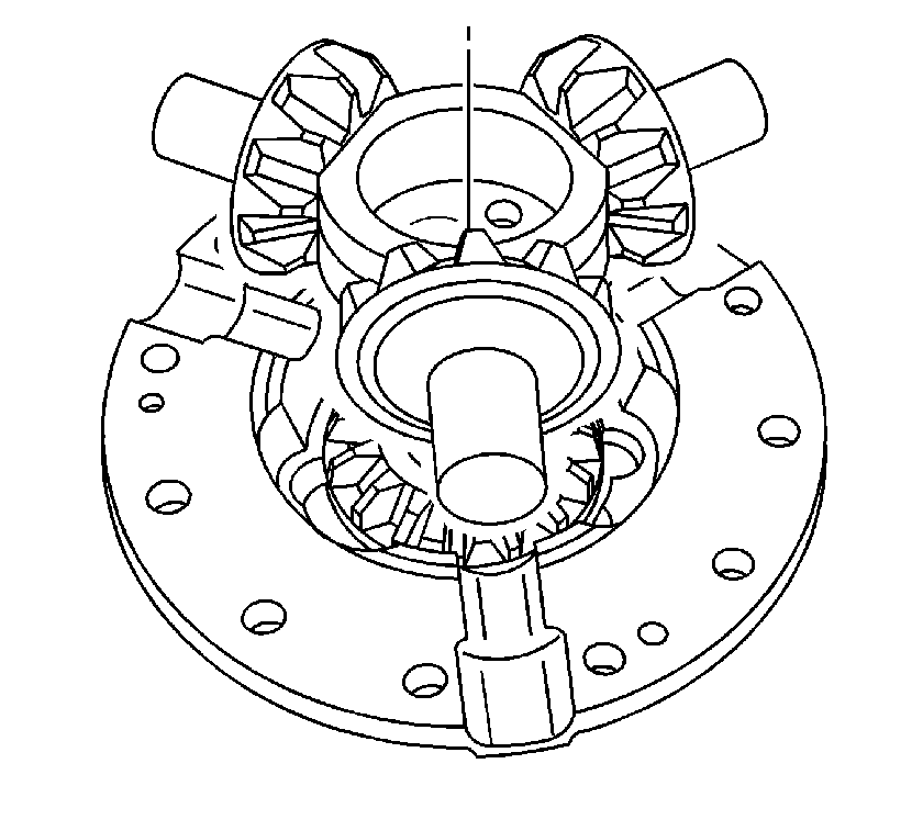
| • | The locking differential spider |
| • | The differential pinion gears |
| • | The differential pinion gear thrust washers |
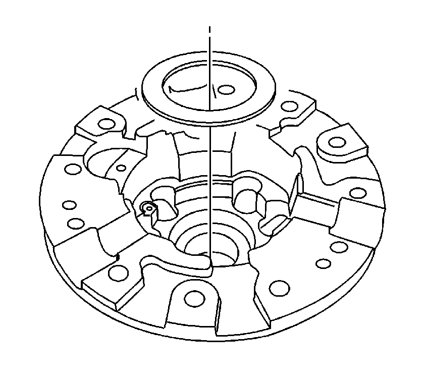
Locking Differential Disassemble 8.6 Inch Axle
Special Tools
J 26252 Locking Differential Governor Remover
- Remove the ring gear, if necessary. Refer to Drive Pinion and Ring Gear Replacement.
- Remove the governor bushing using the J 26252 .
- Remove the governor assembly.
- Remove the latching bracket assembly bushing using the J 26252 .
- Remove the pinion shaft lock bolt.
- Remove the pinion shaft.
- Remove the differential pinion gears and the thrust washers.
- Remove the thrust block.
- Remove the right side gear and clutch discs assembly.
- Remove the right side shim.
- Remove the left side gear cam unit and clutch disc assembly.
- Remove the left side gear thrust washer.
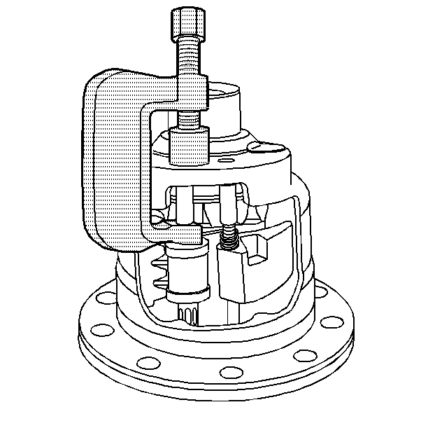
To aid in the removal of the governor assembly, turn the side gear as necessary to position the governor assembly between two of the side gear teeth.
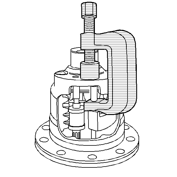
To aid in the removal of the latching bracket assembly, turn the side gear as necessary to position the latching bracket assembly between two of the side gear teeth.
Rotate the pinion gears and roll the pinion gears and the thrust washers out of the case through the differential window.
Mark the pinion gears and thrust washers accordingly for re-assembly.
